Transcription
LECTURE NOTES ONPOWER PLANT ENGINEERING(A70353)IV B.Tech I Semester (JNTUH-R15)Mr. G.SARAT RAJUAssistant ProfessorMrs. G.KARUNYAAssistant ProfessorMECHANICAL ENGINEERINGINSTITUTE OF AERONAUTICAL ENGINEERING(Autonomous)Dundigal, Hyderabad-500043
UNIT-1STEAM POWER PLANTIntroduction:Power Plant Engineering is a science, which deals with the complete study of different types of powerplant.Sources are divided into two types1. Conventional sources (Non-Renewable Sources)-these are consumable sources.Ex: Coal, Diesel, Nuclear activity materials etc.2. Non-conventional sources (Renewable Sources) -these are non-consumable sourcesEx: Solar, Wind, Tidal, Water etc.In India, the following sources are used to generate the power.1. Water energy – It is used in Hydro-Electric Power Plant2. Coal- It is used in Steam Plant3. Diesel- It is used in I.C Engine plant4. Nuclear activity materials- It is used in Nuclear Power Plant5. Non-conventional sources- These are used in Solar, Wind & tidal power plant.RESOURCES OF POWER IN INDIA:The hydel power source plays a vital role in the generation of power, as it is a nonconventional perennial source of energy. Therefore the French cals it ―huile Blanche‖— whiteoil-the power of flowing water. Unlike black oil, it is a non-conventional energy source. A partof the endless cycle in which moisture is raised by the sun, formed into clouds and then droppedback to earth to feed the rivers whose flow can be harnessed to produce hydroelectric power.Water as a source of power is non-polluting which a prime requirement of power industry todayis.The world‘s total waterpower potential is estimated as 1500 million kW at mean flow. Thismeans that the energy generated at a load factor of 50% would be 6.5 million kW-hr,
a quantity equivalent to 3750 million tonnes of coal at 20% efficiency. The world hydel installedcapacity (as per 1963 estimate is only 65 million kW or 4.3% of the mean f l o w .India has colossal waterpower resources. India‘s total mean annual river flows are about1675 thousand million cubic meters of which the usable resources are 555 thousandmillion cubic meters. Out of total river flows, 60% contribution comes from Himalayan Rivers(Ganga, Indus and Brahmaputra). 16% from central Indian rivers (Narmada, Tapti andMahanadi) and the remaining from the rivers draining the Deccan plateau (Godavari, Krishnaand Cauvery). India‘s power potential from hydel source as per the recent estimate is41500 mW while its present hydel capacity is only 32000 mW. Still India has got enoughhydel potential to develop to meet the increasing power needs of the nation. The abundantavailability of water resources, its fairly even distribution and overall economy indeveloping this source of energy enhanced its development in India, The other factorsresponsible in its rapid development are indigenous technological skill, material and cheaplabor. In the IX five-year plan; the Government considering the importance of this sourcehas included a number of hydro-projects. The major difficulty in the development ofhydroelectric projects is the relatively longer time required for its hydrological, topographical andgeological investigations. Lack of suitable. Site is an added problem for taking up hydroprojects.Hydropower was once the dominant source of electrical energy in the world and still is inCanada, Norway and Switzerland. But its use has decreased in other countries since1950s, as relatively less expensive fuel was easily available. In USA, only 10% of thetotal power production is water-generated. In the light of fuel scarcity and its up surgingprices, the role of hydropower is again re-examined and more emphasis is being laid onwaterpower development. As per Mr. Hays (Manager of Hydro Projects in USA), ―It wasless costly per mW to build a single 1000 mW thermal plant than 20 small hydro plants.But, with the increased fuel cost and high cost of meeting environmental criteria for newthermal plants, interest in hydro is being revived‖. Sma ll hydro-projects ranging from 10to 1500 kW are becoming more feasible as standardization of major equipment reducescosts. India is yet to start in the field of micro-hydro projects, which is one major way forsolving the present power problem.Hydro-projects generate power at low cost, it is non conventional, easy to manage,pollution free and makes no crippling demands on the transportation system. But themajor drawback is, it operates at the mercy of nature. Poor rainfall has on a number ofoccasions shown the dangers of over dependence on hydropower. Let rivers flow and letrains shower the earth with prosperity is the ancient prayer chanted by Riches andcontinued to be chanted even now.The development of hydropower systems as a backup for thermal systems has significantadvantages: The flexible operation of hydraulic turbines makes them suitable for. Peak loadoperation. Therefore, the development of hydropower is not only economical but it alsosolves the major problem of peak load.
The present Indian policy of power development gives sufficient importance for thehydel-power development.The next important source for power generation is fuel in the form of coal, oil or gas.Unfortunately, the oil and gas resources are very much limited in India. Only few powerplants use oil or gas as a source of energy. India has to import most of the oil requiredand so it is not desirable to use it for power generation.The known resources of coal in India are estimated to be 121,000 million tonnes,which are localized in West Bengal, Bihar, Madhya Pradesh and Andhra Pradesh.The present rate of annual production of coal is nearly 140 million tonnes of which 40million-tonnes are used for power generation.The coal used for power generation is mainly low-grade c o a l with high ash content(20-40%).The high ash content of Indian coal (40–50%) is one of the causes for bad performanceof the existing steam power plants and their frequency outages, as these plants havebeen designed for low ash coals. Due to the large resources of coal available in thecountry, enough emphasis has been given for thermal Power plants in the IX planperiod.The location of hydel-power plants is mostly determined by the natural topographyavailable and location of thermal plants is dictated by the source of fuel ortransportation facilities available if the, power plant is to be located far fromcoalmines.For nuclear power plant any site can be selected paying due consideration to safetyand load. India has to consider nuclear generation in places remote from coal minesand water power sites.The states which are poor in natural resources and those which have little untappedconventional resources for future development have to consider the development ofnuclear plants.The nuclear fuel which is commonly used for nuclear power plants is uranium. Depositsof uranium have been located in Bihar and Rajasthan. It is estimated that the presentreserves of uranium available in country may be sufficient to sustain 10,000 mWpower plants for its thorium into nuclear Indian lifetime. Another possible nuclearpower source is thorium, which is abundant in this country, estimated at 500,000tonnes.But the commercial use of this nuclear fuel is tied up with development of fast breederreactor which converts energy economy must wait for the development of economicmethods for using thorium which is expected to be available before the end oftwentieth century.The major hurdle in the development of nuclear power in this country is lack oftechnical facility and foreign exchange required to purchase the main componentof nuclear power plant. Dr. Bhabha had envisaged 8000 mW of power from nuclearreactors by 1980–81 which was subsequently scaled down to a more realistic levelof 2700 mW by Dr. Sarabhai out of this only 1040MW has materialized which is lessthan 1.5% of the country‘s insta ll ed power capacity. Moreover the performance of nuclearplants has been satisfactory compared to thermal plants.
DEVELOPMENT OF POWER IN INDIA: The history of power development in India dates back to 1897 when a 200 kW hydrostation was first commissioned at Darjeeling. The first steam station was set up in Calcuttain 1899. By the end of 1920, the total capacity was 130 mW, comprising. Hydro 74 mW,thermal 50 mW and diesel 6 mW. In 1940, the total capacity goes to 1208 mW. There wasvery slow development during 1935-1945 due to Second World War. The total generationcapacity was 1710 mW by the end of 1951. The development really started only after1951 with the launching of the first five-year plan. During the First Plan, construction of a number of Major River Valley Projects like BhakraNangal, Damodar Valley, Hira Kund and Chambal Valley was taken up. These projectsresulted in the stepping up of power generation. At the end of the First Plan, generationcapacity stood at 34.2 lakh kW. Emphasis in Second Plan (1956-61) was on development of basic and heavy industriesand related need to step up power generation. Installed capacity at the end of Second Planreached 57 lakh kW. Comprising 3800 mW thermal and 1900 MW hydel. During the Third Plan period (1961-66), emphasis was on extending power supply torural areas. A significant development in this phase was emergence of Inter-state GridSystem. The country was divided into Five Regions to promote power development on aRegional Basis. Regional Electricity Board was established in each region to promoteintegrated operation of constituent power system. Three Annual Plans that followed Third Plan aimed at consolidating programmes initiatedduring the Third Plan. Fourth Plan envisaged need for central participation in expansion of power generationprogrammes at strategic locations to supplement activities in the State Sector. Progressduring the period covering Third Plan, three Annual Plans and Fourth Plan was substantial with installed capacityrising to 313.07 lakh kW compression; 113.86 lakh kW from Hydro-electric Projects,lakh kW from Thermal Power Projects and balance of 6.4 lakh kW from NuclearProjects at the end of the Fifth Plan. During the Sixth Plan, total capacity addition of 196.66 lakh kW comprising Hydro 47.68lakh kW, Thermal 142.08 lakh kW and Nuclear 6.90 lakh kW was planned.Achievement, however, has been 142.26 lakh kW (28.73 lakh kW Hydro, 108.98 lakhkW Thermal and 4.55 lakh kW Nuclear) 72.3 percent of the target. The Seventh Plan power programme envisaged aggregate generating capacity of 22,245mW in utilities. This comprised 15,999 mW Thermal, 5,541 mW Hydro and 705 mWNuclear of the anticipated 22,245 mW additional capacity. Central Sector Programme
envisaged capacity addition of 9,320 mW (7,950 mW Thermal, 665 mW Hydro and 705mW Nuclear) during the Plan Period. During the Seventh Plan, 21401.48 mW has beenadded comprising 17104.1 mW Thermal 3,827.38 mW Hydro and 470 mW Nuclear.Year wise commissioning of Hydro, Thermal and Nuclear Capacity added during 198586 to 1989-90 is given in. The Working Group on Power set up particularly the Planning Commission in the contextof formulation of power programme for the Eighth Plan has recommended a capacityaddition programme of 38,369 mW for the Eighth Plan period, out of which it is expectedthat the Central Sector Projects would add a capacity of 17,402 mW. The programme forthe first year of the Eighth Plan (1990-91) envisages generation of additional capacity of4,371.5 mW comprising 1,022 mW Hydro, 3,114.5 mW Thermal and 235 mW Nuclear. The subject ‗Power‘ appears in the Concurrent List of the Constitution and as suchresponsibility of its development lies both with Central and state governments. At theCentre, Department of Power under the Ministry of Energy is responsible fordevelopment of Electric Energy. The department is concerned with policy formulation,perspective planning, procuring of projects for investment decisions, monitoring ofprojects, training and manpower development, administration and enactment ofLegislation in regard to power generation, transmission and distribution. The departmentis also responsible for administration of the Electricity (Supply) Act, 1948 and the IndianElectricity Act, 191() and undertakes all amendments thereto. The Electricity (Supply)Act, 1948, forms basis of administrative structure of electricity industry. The Actprovides for setting up of a Central Electricity Authority (CEA) with responsibility, interalia, to develop a National Power Policy and coordinate activities of various agencies andState Electricity Boards. The act was amended in 1976 to enlarge scope and function ofCEA and enable of creation of companies for generation of electricity. The Central Electricity Authority advises Department of Power on technical, financialand economic matters. Construction and operation of generation and transmissionprojects in the Central Sector are entrusted to Central Power Corporations, namely,National Thermal Power Corporation (NTPC), National Hydro-Electric PowerCorporation (NHPC) and North-Eastern Electric Power Corporation (NEEPCU) underadministrative control of the Department of Power. The Damodar Valley Corporation(DVC) constituted under the DVC Act, 1948 and the Bhitkra Beas, Management Board(BBMB) constituted under the Punjab Reorganization. Act, 1966, is also underadministrative control of the Department of Power. In addition, the departmentadministers Beas Construction Board (BCB) and National Projects ConstructionCorporation (NPCC), which are construction agencies and training and researchorganisations, Central Power Research Institute (CPRI) and Power Engineers TrainingSociety (PETS). Programmes of rural electrification are within the purview of RuralElectrification Corporation (REC) which is a financing agency. ‗‗There are two jointventure Power Corporations under the administrative control of the Department of Power,namely, Nathpa jhakri Power Corporation and Tehri Hydro Development Corporationwhich are responsible for the execution of the Nathpa Jhakri
Power Project and Projects of the Tehri Hydro Power Complex respectively. In additionto this, Energy Management Centre, an autonomous body, was established incollaboration with the European Economic Community, which is responsible for training,research, and information exchange between energy professionals. It is also responsiblefor conservation of energy programmes/activities in the Department of Power. Significantprogress has been made in the expansion of transmission and distribution facilities in theCountry. Total length of transmission lines of 66 kV and above increased from 10,000 ckt(circuit) km in December 1950 to 2.02 lakh ckt Km in March, 1990. Highest transmission voltage in the Country at present is 400 kV and above 19800 ckt kmof 400 kV lines had been constructed up to March, 1990 and about 18000 ckt km of theseare in actual operation. Prior to the Fourth Plan, Transmission Systems in the Country weredeveloped more or less as state systems, as generating stations were built primarily in the StateSector. When State Transmission Systems had developed to a reasonable extent in the ThirdPlan, potentiality of inter-connected operation of individual state systems with otherneighboring systems within the region (northern, western, southern, eastern and northeastern) was thought of. Fairly well inter-connected systems at voltage of 220 kV withprogressive overlay of 400 kV are presently available in all regions of the Country exceptNorth-eastern Region. With creation of Two Generation Corporations, namely NationalThermal Power Corporation and National Hydro-Electric Power Corporation in 1975, theCentre had started playing an increasingly larger role in the development of grid systems. The 400 kV transmission systems being constructed by these organizations as part oftheir generation projects, along with 400 kV inter-state and inter-regional transmissionlines would form part of the National Power Grid. National Power Grid will promoteintegrated operation and transfer of power from one system to another with ultimateobjective of ensuring optimum utilization of resources in the Country. India now has wellintegrated Regional Power Systems and exchange of power is taking place regularlybetween a large numbers of state systems, which greatly facilitates better utilization ofexisting capacity.A power plant may be defined as a machine or assembly of equipment thatand delivers a flow of mechanical or electrical energy. The main equipmentgeneration of electric power is generator. When coupling it to a prime movergenerator, the electricity is generated. The type of prime move determines thepower plants. The major power plants are,1. Steam power plant2. Diesel power plant3. Gas turbine power plant4. Nuclear power plant5. Hydro electric power plantgeneratesfor theruns thetype of
The Steam Power Plant, Diesel Power Plant, Gas Turbine Power Plant and Nuclear Power Plants arecalled THERMAL POWER PLANT, because these convert heat into electric energy.Steam is the most common working fluid used in steam/Thermal power plant because of its manydesirable characteristics, such as low cost, availability and high enthalpy of vaporization.Classification of steam power plants:The steam power plants may be classified as follows:1. Central stations2. Industrial power stations or captive power stationsSTEAM POWER PLANT LAYOUT:A steam power plant must have following equipments:1. A furnace to burn the fuel.2. Steam generator or boiler containing water. Heat generated in the furnace is utilized toconvert water in steam.3. Main power unit such as an engine or turbine to use the heat energy of steam and performwork.4.Piping system to convey steam and water. In addition to the above equipment the plant requires various auxiliaries and accessoriesdepending upon the availability of water, fuel and the service for which the plant isintended. A steam power plant using steam as working substance works basically on Rankinecycle. Steam is generated in a boiler, expanded in the prime mover and condensed in thecondenser and fed into the boiler again.
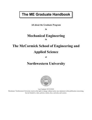
Fig-1.1- layout of steam power plant Layout of thermal plant can be easily understood by dividing the plant componentsinto four circuits. Coal and ash circuit. Air and gas circuit. Feed water and steam circuit. Cooling water circuit
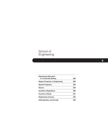
Coal and Ash Circuit:Coal and Ash circuit in a thermal power plant layout mainly takes care of feeding the boiler withcoal from the storage for combustion. The ash that is generated during combustion is collected atthe back of the boiler and removed to the ash storage by scrap conveyors. The combustion in theCoal and Ash circuit is controlled by regulating the speed and the quality of coal entering thegrate and the damper openings.Air and Gas Circuit:Air from the atmosphere is directed into the furnace through the air preheated by the action of a forceddraught fan or induced draught fan. The dust from the air is removed before it enters the combustionchamber of the thermal power plant layout. The exhaust gases from the combustion heat the air,which goes through a heat exchanger and is finally let off into the environment.Fig-1.2-Layout of different circuits10
Feed Water and Steam Circuit:The steam produced in the boiler is supplied to the turbines to generate power. The steam that isexpelled by the prime mover in the thermal power plant layout is then condensed in a condenserfor re-use in the boiler. The condensed water is forced through a pump into the feed waterheaters where it is heated using the steam from different points in the turbine. To make up for thelost steam and water while passing through the various components of the thermal power plantlayout, feed water is supplied through external sources. Feed water is purified in a purifyingplant to reduce the dissolve salts that could scale the boiler tubes.Cooling Water Circuit:The quantity of cooling water required to cool the steam in a thermal power plant layout issignificantly high and hence it is supplied from a natural water source like a lake or a river. Afterpassing through screens that remove particles that can plug the condenser tubes in a thermalpower plant layout, it is passed through the condenser where the steam is condensed. The wateris finally discharged back into the water source after cooling. Cooling water circuit can also be aclosed system where the cooled water is sent through cooling towers for re-use in the powerplant. The cooling water circulation in the condenser of a thermal power plant layout helps inmaintaining a low pressure in the condenser allthroughout.The different types of systems and components used in steam power plant are as follows:(i) High pressure boiler(ii) Prime mover(iii) Condensers and cooling towers(iv) Coal handling system(v) Ash and dust handling system(vi) Draught system(vii) Feed water purification plant(viii) Pumping system(ix) Air preheater, economizer, super heater, feed heaters.Fig-1 shows a schematic arrangement of equipment of a steam power station. Coal received incoal storage yard of power station is transferred in the furnace by coal handling unit. Heatproduced due to burning of coal is utilized in converting water contained in boiler drum intosteam at suitable pressure and temperature. The steam generated is passed through the superheater.Superheated steam then flows through the turbine. After doing work in the turbine die pressureof steam is reduced. Steam leaving the turbine passes through the condenser which maintains thelow pressure of steam at the exhaust of turbine.11
Steam pressure in the condenser depends upon flow rate and temperature of cooling water and oneffectiveness of air removal equipment. Water circulating through the condenser may be takenfrom the various sources such as river, lake or sea. If sufficient quantity of water is not availablethe hot water coming out of the condenser may be cooled in cooling towers and circulated againthrough the condenser.Bled steam taken from the turbine at suitable extraction points is sent to low pressure and highpressure water heaters.Air taken from the atmosphere is first passed through the air pre-heater, where it is heated by fluegases. The hot air then passes through the furnace.The flue gases after passing over boiler and super heater tubes, flow through the dust collectorand then through economizer, air pre-heater and finally they are exhausted to the atmospherethrough the chimney.ADVANTAGES:1. They can be located very conveniently near the load centers.2. Does not require shielding like required in nuclear power plants.3. Unlike nuclear power plants whose power production method is difficult, for thermal powerplants it is easy if compared.4. Transmission costs are reduced as they can be set up near the industry.5. The portion of steam generated can be used as process steam in different industries.6. Steam engines and turbines can work under 25% of overload capacity.DISADVANTAGES:1.2.3.4.5.6.Large amounts of water are required.Great difficulties experienced in coal handling and disposal of ash.Takes long time to be erected and put into action.Maintenance and operating costs are high.With increase in pressure and temperature, the cost of plant increases.Troubles from smoke and heat from the plant.TYPES OF COALS: PeatLigniteSub-Bituminous coalBituminous coalAnthracite coal12
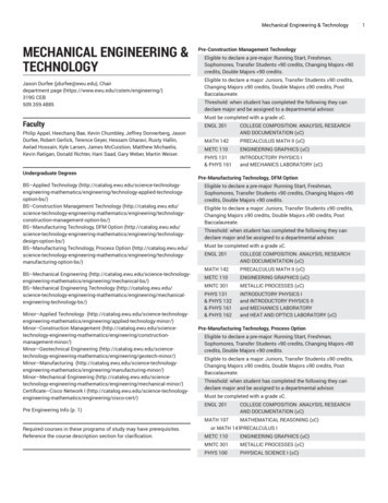
Peat Starting stage of coal formation and is not useful in power plants.Lignite is the youngest form of coal. It is soft and ranges in color from black to shades of brown.As a result, it‘s sometimes caled brown coal. Lignite is mainly used for power generation andaccounts for 17 percent of the world‘s coal reserves.Sub-bituminous coal: After millions of years, continued pressure and temperature convertlignite into sub-bituminous coal. It burns more cleanly than other types of coal due to its lowsulfur content. Sub-bituminous coal has applications in power generation and also in industrialprocesses. This type of coal makes up 30 percent of the world‘s coal reserves.Bituminous coal is harder and blacker than lignite and sub-bituminous coal, and can be dividedinto two types: thermal and metal urgical. Together, they make up 52 percent of the world‘s coalreserves. Thermal coal is mostly used for power generation, cement manufacturing and otherindustrial purposes, while metallurgical coal is used primarily for manufacturing iron and steel.Anthracite is the most mature coal and thus has the highest carbon content of any type of coal. Itis frequently used for home heating and, accounting for about 1 percent of the world‘s total coalreserves, represents a very small portion of the overall market. Anthracite coal can be used as asmokeless fuel in domestic and industrial contexts.FUEL AND HANDLING EQUIPMENTS:The various stages are involved in the fuel handling system from coal delivery to furnace inthe steam plant1. Coal delivery2. Unloading3. Preparation4. Transfer5. Storage6. In plant handling7. Weighing8. Feeding the coal into Furnace.13
Fig-1.3-steps in coal handling(i)(ii)(iii)Coal Delivery. The coal from supply points is delivered by ships or boats to powerstations situated near to sea or river whereas coal is supplied by rail or trucks to the powerstations which are situated away from sea or river. The transportation of coal by trucksis used if the railway facilities are not available.Unloading. The type of equipment to be used for unloading the coal received at the powerstation depends on how coal is received at the power station. If coal is delivered bytrucks, there is no need of unloading device as the trucks may dump the coal to theoutdoor storage. Coal is easily handled if the lift trucks with scoop are used. In casethe coal is brought by railway wagons, ships or boats, the unloading may be done bycar shakes, rotary car dumpers, cranes, grab buckets and coal accelerators. Rotary cardumpers although costly are quite efficient for unloading closed wagons.Preparation. When the coal delivered is in the form of big lumps and it is not of propersize, the preparation (sizing) of coal can be achieved by crushers, breakers, sizers, driersand magnetic separators.14
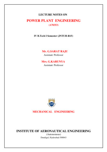
(iv)Transfer. After preparation coal is transferred to the dead storage by means of thefollowing systems :1.2.3.4.5.6.Belt conveyors.Screw conveyors.Bucket elevators.Grab bucket elevators.Skip hoists.Flight conveyor.1. Belt conveyor.Fig.1.4 shows a belt conveyor. It consists of an endless belt. Moving over a pair of enddrums (rollers). At some distance a supporting roller is provided at the center. The belt ismade, up of rubber or canvas. Belt conveyor is suitable for the transfer of coal over longdistances. It is used in medium and large power plants. The initial cost of the system isnot high and power consumption is also low. The inclination at which coal can besuccessfully elevated by belt conveyor is about 20. Average speed of belt conveyorsvaries between 200-300 r.p.m. This conveyor is preferred than other types.Fig-1.4-Belt ConveyorAdvantages of belt conveyor:1.2.3.4.Its operation is smooth and clean.It requires less power as compared to other types of systems.Large quantities of coal can be discharged quickly and continuously.Material can be transported on moderates inclines.2. Screw conveyor:It consists of an endless helicoids screw fitted to a shaft (Fig.1.5).The screw while rotating in atrough transfers the coal from feeding end to the discharge end. This system is suitable, wherecoal is to be transferred over shorter distance and space limitations exist. The initial cost of thesystem is low. It suffers from the drawbacks that the power consumption is high and there isconsiderable wear of screw. Rotation of screw varies between 75-125 r.p.m.15
Fig-1.5-Screw conveyorFig-1.6- bucket conveyor3. Bucket elevator. It consists of buckets fixed to a chain (Fig.1.6). The chain moves over twowheels. The coal is carried by the buckets from bottom and discharged at the top.4. Grab bucket elevator. It lifts and transfers coal on a single rail or track from one point to theother. The coal lifted by grab buckets is transferred to overhead bunker or storage. This systemrequires less power for operation and requires minimum maintenance. The grab bucket conveyorcan be used with crane or tower as shown in Fig.7. Although the initial cost of this system ishigh but operating cost is less.Fig-1.7- Grab bucket elevatorFig-1.8-Skip Hoist5. Skip hoist. It consists of a vertical or inclined hoist way a bucket or a car guided by a frameand a cable for hoisting the bucket. The bucket is held in upright position. It is simple andcompact method of elevating coal or ash. Fig.1.8 shows a skip hoist.6. Flight conveyor. It consists of one or two strands of chain to which steel scraper or flights areattached‘ which scrap the coal through a trough having identical shape. This16
coal is discharged in the bottom of trough. It is low in first cost but has large energy consumption.There is considerable wear.Fig-1.9-Flight ConveyorSkip hoist and bucket elevators lift the coal vertically while Belts and flight conveyors movethe coal horizontally or on inclines. Fig.9 shows a flight conveyor.Flight conveyors possess the following advantages.(i)They can be used to transfer coal as well as ash.(ii)The speed of conveyor can be regulated easily.(iii)They have a rugged construction.(iv)They need little operational care.Disadvantages.Various disadvantages of flight conveyors are as follows:(i)There is more wear due to dragging action.(ii)Power consumption is more.(iii)Maintenance cost is high.(iv)Due to abrasive nature of material handled the speed of conveyors is low (10 to 30m/min).Storage of coal. It is desirable that sufficient quantity of coal should be stored. Storage of coalgives protection against the interruption of coal supplies when there is delay in transportation ofcoal or due to stri
MECHANICAL ENGINEERING INSTITUTE OF AERONAUTICAL ENGINEERING (Autonomous) Dundigal, Hyderabad-500043 . UNIT-1 STEAM POWER PLANT Introduction: Power Plant Engineering is a science, which deals with the complete study of different types of power plant. Sources are divided into two types