Transcription
LETTER REPI3LI5OVER SHEETEvaluation of Revised Approach «Lighting Criteria ,/J( IN I I "iMllp?LR 6:lINTRODUCTIONVMTfie Federal Aviation Administration (FAA) has directed conversion of all ALSF-1,Category I ILS approach lighting systems with sequenced flashing lights to theSimplified Short Approach Lighting System with Runway Alignment Indicator Lights(SSALR) and Medium intensity Approach Lighting System with Runway Alignment Lights(MALSR).Although the FAA directive affects civilian aerodromes only, the Air Force isconcerned that the lighting change may have an adverse affect on the operationalcapability of the Air National Guard, Air Force Reserve, and Air Defense Commandunits which operate from these airfields.OCOTherefore, Headquarters Air Force has requested the/USAF(histrument Flight Center(USAFIFC) conduct an in-flight pilot factors (PIFAX) evaTuation of the SSALR andMALSR approach lighting system. This evaluation will provide the data necessary forthe Air Force to formulate a position on the operational acceptability of the SSALRand MALSR systems.This interim report summarizes the IFC/RD findings of the pre-validatlon portionof this evaluation.NOTE:The pre-valfd tion flights were conducted in VFR weather conditions,Approve : pabiis roleawjHeadquarters USAFet '.INH(N0 j AT ECOMPL! TiON r.AMi ,1T-38April 1976PROJfl;T'TTfjT *lR- t.«r Ii.Major Kenneth J. KerkeringpaOJECRandolph AFB TX1okFiri"P"TEL "P-r,n i, I-; oLNMNE.t«IFC/RDUMr Gabriel P. IntanoCVt ygNNETH J ERKERING/ (ffi. USAFJUNyCONCOHI H. CARPENTCR, Lt Col. USf\F» Fighter/TrainerBr/IFC/RD - I FC/RDFÖFFICI SYM8CLChief, Research andDevelopment Div/IFCIFC/RDöFVICE SYMBOL"I TITLEID F. RftBILLARD. Col. USA I --H-) I278527852785TELTPHONf (Ti LE( ( fcPPPOv *I IFC/RDUIFC/RDU.ChiefrfeunmAsa-A-f YTT " «71 "Ö CE SYMBOL ' , T CL EPH'j , (7Öi.Mr George A. RexMr Orrin C. KopffOlSTRlSUTICN4114frv IFC/RDFrSYSTEMS ENSINEERJ Htt MConriander/IFC IFC/CC4114TELLPHONfF4114TEL t-PHOMt FV3320407 2p/
/ tCONCLUSIONSGeneral:1. The five-step intensity levels of ALSF-1 and the modified SSALRapproach lighting systems were much more adaptable to varying ambientlight conditions.2. The ALSF-1 approach lighting system was acquired at a much greaterdistance from the runway than the MALSR lighting system under similarconditions,3. The SSALR system with modified intensity levels, comparable to theALSF-1 system, was acquired at a greater distance from the runway thanthe MALSR system under similar conditions.4. The sequenced flashers on the ALSF-1 system did not give a definiteflow toward the runway with the approach lights set on step 5 (fullbright).5. The sequenced flashers on the MALSR system did not provide a definitemovement toward the runway. They looked as if they were flashing in arandom manner.6. It was found at several fields that the MALSR lighting system was notproperly aligned with the instrument approach flightpath. This made theapproach lights and sequenced flashes very difficult to acquire.7. Generally airfields which have ALSF-1 systems that were supposed tobe converted to MALSR have not been converted.8. Roll bars on the MALSR system tended to be less definitive than thoseon the ALSF-1 system.RECOMMENDATIONSAll of the approaches flown against the three lighting systems wereflown under VFR weather conditions. Viewing the various approach lightingsystems under these circumstances, no definite conclusions could be drawnas to the relative value of each system under low ceiling and visibilityconditions; however, based on the general conclusions, an In-depth studyof the approach lighting systems at Category I ILS minimums (200 - 1/2) Isfelt to be warranted before a committment'is made to modify existingapproach lighting.DESCRIPTION OF TEST ITEMSPilot factors test data will be collected on three Category I ILSapproach lighting systems. These are: Approach Lighting System withSequenced Flashing Lights (ALSF-1), the Simplified Short Approach Lighting
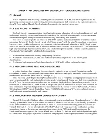
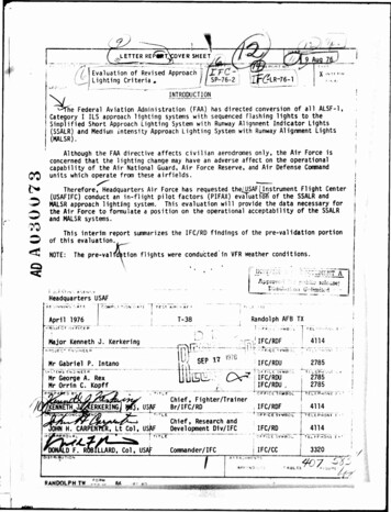
System with Runway Alignment Indicator Lights (SSALR) and Medium IntensityApproach Lighting System with Runway Alignment Indicator Lights (MALSR).The Category I ALSF-1 (figure 1) consists of a light bar (approximately 13-1/2 feet long with five equally spaced lights) at each 100-footinterval starting 200 feet from the runway threshold and continuing outto 3000 feet from the threshold. All light bars are installed perpendicular to the extended runway centerline and all lights are aimed awayfrom the runway threshold. The centerline light bar at 1000 feet fromthe threshold is supplemented with eight additional lights on either sideforming a light bar of 100 feet and containing 21 lights. This bar iscalled the 1000-foot distance marker crossbar (or simply, 1000-foot bar).All of the aforementioned lights are white. The light bar 200 feet fromthe threshold is 50 feet long, contains 11 red lights, and is callad theterminating bar. Two light bars, each containing five red lights, arelocated 100 feet from the threshold, one on either side of the centerline,and are called wing bars. The inner light (nearest runway centerline) ofeach wing bar is located in line with the runway edge lights. A row ofgreen lights on five-foot centers is located near the threshold andextends across the runway threshold and outwards a distance of approximately45 feet frcm the runway edge on either side of the runway. These lightsare called the threshold bar. In addition to the steady burning lights,the ALSF-1 configuration is augmented with a system of sequenced flashinglights. One such light is installed at each centerline bar starting 1000feet from the threshold out to the end of the system 3000 feet from thethreshold. These flashing lights emit a bluish-white light and flash insequence toward the threshold at a rate of twice per second. The flashinglights appear as a ball of light traveling toward the runway threshold ata speed of approximately 4100 miles per hour.The SSALR lighting system (figure 2) consists of seven five-light barslocated on the extended runway centerline with the first bar located 200feet from the runway threshold and at each 200-foot interval out to 1400feet from the threshold. Two additional five-light bars are located, oneto either side of the centerline bar, 1000 feet from the runway thresholdforming a crossbar 70 feet long. The spacing between individual lights is40-1/2 Inches for the centerline bars and five feet for other bars. Alllights in the system are white. In addition. Runway Alignment IndicatorLights (RAIL) are Included. The RAIL portion of the facility consists ofsequenced flashers located on the extended runway centerline, the firstbeing located 1600 feet beyond the approach end of the runway thresholdwith successive units located at each 200-foot Interval out to the end ofthe system (2400 or 3000 feet). These lights flash in sequence toward thethreshold at the rate of twice per second.The length of the SSALR may either be 2400 feet or 3000 feet, dependingon the glide slope angle. When the glide slope angle is less than 2.75 ,the length of the approach lighting system will be 3000 feet, and 2400 feetwhen the glide slope angle Is 2.75 or higher (figure 2).: .
Ho toHHÄOozzzQi-IintoQ QBoz! t-izw2Gozu,»-«ou tul/Jzo. r» »uz -(u cuto.i1OWKtoHSLOwmt-lJtO.sO iZlO - HHXZOOMO JoJ'-ILOdHICoM-JIX.K lü1—1l-lX3sainroUJlt. s UI o2ilJn3oISSHmJllllj. Ill PD i
CWUJDi tj0z1—(u- uo a,HXu LOODi-t-l1-1zt-lzg3:C(-1 JCO Q fcto2-.M3:CO- OCO rHCDO ': Ü tohH HH X : 0O »-HU Jcfz0t-tH1 nU UJM t—l/lfc« - ; OOrt Jmt/10OLlto OOOnrv"Oc§OOOz& ndi&#*\fix INl'ldiiNi AVrtN/ia5-1 i -ciA-i—is»»»»»"-—
The MALSR consists of seven five-light bars located on the extendedrunway centerline with the first bar located 200 feet from the runwaythreshold and at each 200-foot interval out to 1400 feet from the threshold. Two additional five-light bars are located, one to either side ofthe centerline bar 1000 feet from the runway threshold forming a crossbar 66 feet long. The spacing between individual lights in all bars isapproximately 2.5 feet. The RAIL portion of the facility consists ofsequenced flashers located on the extended runway centerline, the firstbeing located 1600 feet beyond the approach end of the runway thresholdwith successive units located at each 200-foot interval out to the endof the system (1 100 or 3000 feet). These lights flash in sequence towardthe threshold at the rate of twice per second.As with the SSALR system, the MALSR may either be 2400 or 3000 feet,depending on the glide slope angle. When the glide slope angle is lessthan 2.75 , the length of the approach lighting system will be 3000 feetand 2400 feet when the glide slope angle is 2.75 or higher (figure 3).DISCUSSIONThe pre-valldation portion of SP 76-2 has consisted of finding suitable operating locations throughout the United States. Various flightprofiles and equipment to be used in the data acquisition portion of theproject were also examined.Several factors were considered -'hen selecting the operating locations:the type of approach lighting system at each airfield, the capabilities ofthe airfields to support T-38 operations, and the necessity for the weatherto be at 200 - 1/2 for extended periods of time were all extremely important.Initially the lighting systems at airfields in the Randolph AFB areaof operations were investigated. All of these airfields had either theALSF-1 or MALSR approach lighting systems. After these fields were examined,the area of operation was then expanded to include airfields throughout theUnited StatesIn our quest for acceptable operating locations, the California SanJoaquin Valley was found to meet all the necessary criteria. In the wintermonths there is a high probability of fog and low ceilings; also within a60-mile radius of a suitable support base there are three airfields withthe lighting systems to be evaluated.It was discovered after several pre-validation flights that the airfieldapproach lighting systems that were flown against in California were bettermaintained than those in other parts of the United States. It was generallyfelt that the reason for this was because of the high Incidence of fog andlow ceilings in the winter months which necessitates the systems be kept Intop-notch condition. In other parts of the United States, approach lightingsystems were found to have poorly aimed sequenced flashers, inoperative4iML
O Hotoza: cCD -H»- uoz isMtcI s(0u 1/1rH inU-4tuet: ooUU r-lImCOO (SoC*- aJC-MXi 1oco§CM wooootoOOOC»ouooOCXjXDOX.BOt-cooooto rjCDO2*7ofjuoooCXXXOÖOOOOooooor .8Zn oOC3)O"I* .BZ oooooooCM oooooooot— ooo PQiooOooooon Joa:wrsjooooo Iti ipiEI-J—Ii i j- icnoHsaHHiiCJ—i—iAvwNna-aNnnaiNaDAV/UUIH/ «v» iMfeooonc " * asian«* - '*" "'"'-'U' fefc-.H
sequenced flashers, and approach lights burned out or improperly aimed.When the sequenced flashers and approach lights were properly maintainedand aimed to coincide with the instrument approach path, they could beacquired at a much greater distance from the runway.Most airfields have gone to the MALSR system. Some of the older airfields located in areas where poor weather conditions are frequent, maintain ALSF-1 systems. Only three fields could be found with operable SSALRsystems.After some Investigation it was found there is a vast difference inthe intensity levels of the various approach lighting systems. When comparing the three approach lighting systems; the intensity level for ALSF-1and modified SSALR are the same. The ALSF-1 and modified SSALR systemshave a five-step Intensity level. The sequenced flasher intensity levelfor these two systems is not varied.The MALSR and SSALR systems have three brightness controls for thesteady burning lights; high, medium, or low. Both systems take power fromthe runway edge lights to control the flasher intensity, therefore, theflasher intensity depends on the edge light step setting. When the runwayedge lights are on steps five or four, the MALSR and SSALR systems are HIGHand the flasher intensity is 100?.When the edge lights are step three, the MALSR and SSALR systems areMED, and the flasher intensity is 8% brightness (8% of what you normallysee on an ALSF-1 or 2).When runway edge lights are on steps two or one, the MALSR and SSALRsystems are LOW, and the flashers are only 1%.Table 1.Runway EdgeLight Step4 or 531SSALRMALSRStepSSALRMALSRSteadyBurning aches were flown with the lighing systems set at various intensitylevels. Comments from the project pilot as to the distance sequenced flashersand approach lights were first seen as well as when they were lost from viewon missed approach were recorded. Recording of the subject pilot's commentswas accomplished by use of a small cassette tape recorder and wiring jackthat plugged Into the aircraft's interphone system. Notes were also takendim
by the project pilot. During the initial flights against these approachlighting systems, it was felt some type of video recording device wouldbe of value to review and analyze the approaches after the mission wascompleted. A Sony Video Rover §2 television camera with video taperecorder was tried. It was found after several flights, this camera wouldbe difficult to mount and also present some difficulty for the subjectpilots to operate without extensive training. The camera worked well forthe daylight approaches, but proved totally unacceptable for recordingapproach lighting at night. A KB 26A gunsight camera was obtained. Thiswill be mounted on the glare shield of the test aircraft when the Class IImodification package is approved. It should prove to be invaluable forrecording the approaches both during day and night conditions. In theinterim, some film has been taken using a conventional super 8 moviecamera.When suitable weather conditions occur, i.e., low ceilings and visibility in the fall and winter months, the evaluation of the approachlighting systems will continue.---' —
Approach Lighting System with Runway Alignment Indicator Lights (MALSR). The Category I ALSF-1 (figure 1) consists of a light bar (approxi- mately 13-1/2 feet long with five equally spaced lights) at each 100-foot interval starting 200 feet from the runway threshold and continuing out to 3000 feet from the threshold.