Transcription
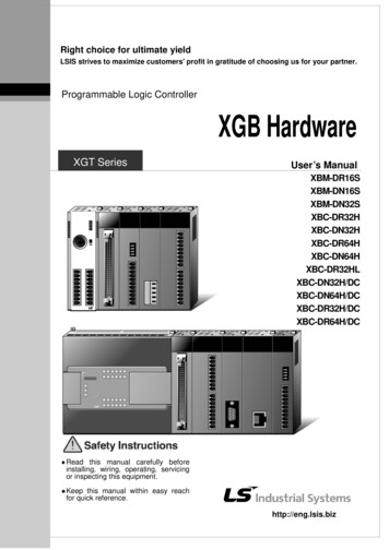
Right choice for ultimate yieldLSIS strives to maximize customers' profit in gratitude of choosing us for your partner.Programmable Logic ControllerXGB HardwareXGT SeriesUser’s /DCXBC-DR32H/DCXBC-DR64H/DCz Readthis manual carefully beforeinstalling, wiring, operating, servicingor inspecting this equipment.z Keepthis manual within easy reachfor quick reference.http://eng.lsis.biz
Safety InstructionBefore using the product For your safety and effective operation, please read the safety instructionsthoroughly before using the product. Safety Instructions should always be observed in order to prevent accidentor risk with the safe and proper use the product. Instructions are separated into “Warning” and “Caution”, and the meaning ofthe terms is as follows;WarningThis symbol indicates the possibility of serious injuryor death if some applicable instruction is violatedCautionThis symbol indicates the possibility of slight injuryor damage to products if some applicable instructionis violated The marks displayed on the product and in the user’s manual have thefollowing meanings.Be careful! Danger may be expected.Be careful! Electric shock may occur. The user’s manual even after read shall be kept available and accessible toany user of the product.
Safety InstructionSafety Instructions when designingWarning Please, install protection circuit on the exterior of PLC to protectthe whole control system from any error in external power or PLCmodule. Any abnormal output or operation may cause serious problemin safety of the whole system.- Install applicable protection unit on the exterior of PLC to protectthe system from physical damage such as emergent stop switch,protection circuit, the upper/lowest limit switch, forward/reverseoperation interlock circuit, etc.- If any system error (watch-dog timer error, module installation error,etc.) is detected during CPU operation in PLC, the whole output isdesigned to be turned off and stopped for system safety. However,in case CPU error if caused on output device itself such as relay orTR can not be detected, the output may be kept on, which maycause serious problems. Thus, you are recommended to install anaddition circuit to monitor the output status. Never connect the overload than rated to the output module norallow the output circuit to have a short circuit, which may cause afire. Never let the external power of the output circuit be designed tobe On earlier than PLC power, which may cause abnormal output oroperation. In case of data exchange between computer or other externalequipment and PLC through communication or any operation ofPLC (e.g. operation mode change), please install interlock in thesequence program to protect the system from any error. If not, itmay cause abnormal output or operation.
Safety InstructionSafety Instructions when designingCaution I/O signal or communication line shall be wired at least 100mmaway from a high-voltage cable or power line. If not, it may causeabnormal output or operation.Safety Instructions when designingCaution Use PLC only in the environment specified in PLC manual orgeneral standard of data sheet. If not, electric shock, fire, abnormaloperation of the product or flames may be caused. Before installing the module, be sure PLC power is off. If not,electric shock or damage on the product may be caused. Be sure that each module of PLC is correctly secured. If theproduct is installed loosely or incorrectly, abnormal operation, error ordropping may be caused. Be sure that I/O or extension connecter is correctly secured. Ifnot, electric shock, fire or abnormal operation may be caused. If lots of vibration is expected in the installation environment,don’t let PLC directly vibrated. Electric shock, fire or abnormaloperation may be caused. Don’t let any metallic foreign materials inside the product, whichmay cause electric shock, fire or abnormal operation.
Safety InstructionSafety Instructions when wiringWarning Prior to wiring, be sure that power of PLC and external power isturned off. If not, electric shock or damage on the product may becaused. Before PLC system is powered on, be sure that all the covers ofthe terminal are securely closed. If not, electric shock may be causedCaution Let the wiring installed correctly after checking the voltage ratedof each product and the arrangement of terminals. If not, fire,electric shock or abnormal operation may be caused. Secure the screws of terminals tightly with specified torque whenwiring. If the screws of terminals get loose, short circuit, fire or abnormaloperation may be caused.* Surely use the ground wire of Class 3 for FG terminals, which isexclusively used for PLC. If the terminals not grounded correctly,abnormal operation may be caused. Don’t let any foreign materials such as wiring waste inside themodule while wiring, which may cause fire, damage on the productor abnormal operation.
Safety InstructionSafety Instructions for test-operation or repairWarning Don’t touch the terminal when powered. Electric shock or abnormaloperation may occur. Prior to cleaning or tightening the terminal screws, let all theexternal power off including PLC power. If not, electric shock orabnormal operation may occur. Don’t let the battery recharged, disassembled, heated, short orsoldered. Heat, explosion or ignition may cause injuries or fire.Caution Don’t remove PCB from the module case nor remodel the module.Fire, electric shock or abnormal operation may occur. Prior to installing or disassembling the module, let all the externalpower off including PLC power. If not, electric shock or abnormaloperation may occur. Keep any wireless installations or cell phone at least 30cm awayfrom PLC. If not, abnormal operation may be caused.Safety Instructions for waste disposalCaution Product or battery waste shall be processed as industrial waste.The waste may discharge toxic materials or explode itself.
Revision HistoryVersionDateRemarkPageV 1.02006.61. First Edition-V 1.12007.71. Position and Special function contents separated(1) Position function contents separated(position part published)-(2) PID control and Ch. 12 Analog IO module contentsseparated2. Contents added(1) Naming standard added(2) Caution when selecting IO module added(3) IO wiring method by using Smart Link board added(4) Installation and wiring contents added3. Content modified(1) Safety instruction modified(2) System Configuration modified(3) High speed counter function modified(4) External dimension modifiedV 1.22008.31. XGB compact type ‘H’ type added2. Built-in communication content separated(1) Ch.9 built-in communication function separated(Cnet I/F user manual)2-3 2-67-1 7-67-27 7-2810-1 10-181 62-7 2-108-6 8-8App. 2-1 2-4Ch. 9V1.32009.31. Specification of output for positioning added7-13,14,17,18V1.62010.31. “UL warranty voltage” word added4-62. RTC example program modified6-223. XBC input resistor modified and Mixed module I/O7-26specification added4. Installation of module added5. DC power unit added9-10Front cover6. DC power unit and expansion module added2-1 2-47. DC power unit and expansion module added4-6 4-78. DC power unit and expansion module addedChapter 79. DC power unit and expansion module addedAppendix 210. Error in high speed counter channel fixed11. Specification of TR output for positioning modified8-37-13, 14, 17, 18
VersionDateRemarkPage12. Error in figure fixed4-413. External memory module addedCh6.1314. XGB compact type mode addedFront cover15. ‘S’, ‘H’ type max. I/O point modified2-1 2-416. ‘S’, ‘H’ type max. I/O point modified4-1 4-2※ The number of User’s manual is indicated the right side of the back cover. LS Industrial Systems Co., Ltd2006All Rights Reserved.
About User’s ManualAbout User’s ManualCongratulations on purchasing PLC of LS Industrial System Co.,Ltd.Before use, make sure to carefully read and understand the User’s Manual about the functions,performances, installation and programming of the product you purchased in order for correct use andimportantly, let the end user and maintenance administrator to be provided with the User’s Manual.The Use’s Manual describes the product. If necessary, you may refer to the following description and orderaccordingly. In addition, you may connect our website(http://eng.lsis.biz/) and download the information as aPDF file.Relevant User’s ManualTitleXG5000 User’sManualNo. of UserDescriptionManualIt describes how to use XG5000 software especially aboutonline functions such as programming, printing, monitoring10310000512and debugging by using XGT series products.XGK/XGB SeriesIt describes how to use the instructions for programmingInstruction &using XGK/XGB series.10310000510ProgrammingXGB HardwareUser’s ManualXGB AnalogUser’s ManualIt describes how to use the specification of power/input/output/expansion modules, system configuration and built-inHigh-speed counter for XGB basic unit.It describes how to use the specification of stemIt describes how to use built-in communication function forUser’s ManualXGB basic unit and external Cnet I/F module.User’s Manual10310000920configuration and built-in PID control for XGB basic unit.XGB Cnet I/FXGB Fast Ethernet I/F10310000926It describes how to use XGB FEnet I/F module.1031000081610310000873
Chapter 1 IntroductionContents . 1-1 1-51.1 Guide to Use This Manual . 1-11.2 Features. 1-21.3 Terminology . 1-4Chapter 2 System Configuration. 2-1 2-112.1 XGB System Configuration . 2-12.2 Product List . 2-32.3 Classification and Type of Product Name . 2-42.3.1 Classification and type of basic unit .2-42.3.2 Classification and type of expansion module .2-52.3.3 Classification and type of special module .2-62.3.4 Classification and type of communication module .2-72.4 System Configuration . 2-82.4.1 Cnet I/F system .2-82.4.2 Ethernet system.2-11Chapter 3 General Specifications . 3-13.1 General Specifications . 3-1Chapter 4 CPU Specifications . 4-1 4-114.1 Performance Specifications . 4-14.2 Names of Part and Function . 4-44.3 Power Supply Specifications . 4-64.4 Calculating Example of Consumption Current/Voltage . 4-84.5 Battery . 4-10
4.5.1 Battery specification .4-104.5.2 Notice in using .4-104.5.3 Life of battery.4-104.5.4 How to change the battery .4-11Chapter 5 Program Configuration and Operation Method. 5-1 5-365.1 Program Instruction . 5-15.1.1 Program execution methods .5-15.1.2 Operation processing during momentary power failure .5-25.1.3 Scan time .5-35.1.4 Scan Watchdog timer .5-45.1.5 Timer processing .5-55.1.6 Counter processing .5-85.2 Program Execution . 5-105.2.1 Configuration of program .5-105.2.2 Program execution methods .5-105.2.3 Interrupt . .5-125.3 Operation Mode . 5-245.3.1 RUN mode .5-245.3.2 STOP mode .5-255.3.3 DEBUG mode .5-255.3.4 Change operation mode .5-295.4 Memory. 5-305.4.1 Data memory .5-305.5 Configuration Diagram of Data Memory . 5-325.5.1 “S” type .5-325.5.2 “H” type .5-335.5.3 Data latch area setting.5-34Chapter 6 CPU Functions . 6-1 6-226.1 Type Setting . 6-16.2 Parameter Setting . 6-26.2.1 Basic parameter setting .6-2
6.2.2 I/O parameter setting .6-36.3 Self-diagnosis Function . 6-46.3.1 Saving of error log .6-46.3.2 Troubleshooting .6-56.4 Remote Functions. 6-66.5 Forced Input/Output On and Off Function . 6-76.5.1 Force I/O setup .6-76.5.2 Processing time and method of Forced Input/Output On and Off .6-86.6 Direct Input/Output Operation . 6-86.7 Diagnosis of External Device . 6-96.8 Allocation of Input/Output Number . 6-106.9 Online Editing . 6-126.10 Reading Input/Output Information. 6-156.11 Monitoring . 6-166.12 RTC function. 6-216.12.1 How to use .6-216.13 External Memory Module . 6-236.13.1 Structure .6-236.13.2 How to use .6-23Chapter 7 Input/Output Specifications . 7-1 7-287.1 Introduction . 7-17.2 Basic Digital Input Unit Specifications . 7-77.2.1 XBM-DR16S input unit (Source/Sink type) .7-77.2.2 XBM-DN16S input unit (Source/Sink type) .7-87.2.3 XBM-DN32S input unit (Source/Sink type) .7-97.2.4 XBC-DR32H / XBC-DN32H input unit (Source/Sink type).7-107.2.5 XBC-DR64H / XBC-DN64H input unit (Source/Sink Type).7-117.3 Basic Digital Output Unit Specifications . 7-127.3.1 XBM-DR16S relay output unit.7-127.3.2 XBM-DN16S transistor output unit (Sink type).7-137.3.3 XBM-DN32S transistor output unit (Sink type).7-147.3.4 XBC-DR32H output unit .7-157.3.5 XBC-DR64H output unit .7-167.3.6 XBC-DN32H output unit (Sink type) .7-17
7.3.7 XBC-DN64H output unit (Sink type) .7-187.4 Digital Input Module Specifications . 7-197.4.1 8 point DC24V input module (Source/Sink type) .7-197.4.2 16 point DC24V input module (Source/Sink type) .7-207.4.3 32 point DC24V input module (Source/Sink type) .7-217.5 Digital Output Module Specifications . 7-227.5.1 8 point relay output module.7-227.5.2 16 point relay output module.7-237.5.3 8 point transistor output module (Sink type) .7-247.5.4 16 point transistor output module (Sink type) .7-257.5.5 32 point transistor output module (Sink type) .7-267.6 IO Wiring by Using Smart Link Board . 7-277.6.1 Smart link board .7-27Chapter 8 Built-in High-speed Counter Function . 8-1 8-548.1 High-speed Counter Specifications. 8-18.1.1 Performance specifications .8-18.1.2 Designation of parts .8-28.1.3 “S” type Functions.8-68.1.4 “H” type Functions.8-238.2 Installation and Wiring . 8-408.2.1 Precaution for wiring .8-408.2.2 Example of wiring .8-408.3 Internal Memory . 8-418.3.1 Special area for High-speed counter .8-418.3.2 Error code .8-498.4 Examples: Using High-speed Counter . 8-50Chapter 9 Installation and Wiring . 9-1 9-179.1 Safety Instruction . 9-19.1.1 Fail safe circuit .9-39.1.2 PLC heat calculation .9-69.2 Attachment/Detachment of Modules . 9-8
9.2.1 Attachment/Detachment of modules.9-89.2.2 Caution in handling .9-129.3 Wire . 9-139.3.1 Power wiring.9-139.3.2 I/O Device wiring .9-169.3.3 Grounding wiring .9-169.3.4 Specifications of wiring cable .9-17Chapter 10 Maintenance . 10-1 10-210.1 Maintenance and Inspection . 10-110.2 Daily Inspection . 10-110.3 Periodic Inspection . 10-2Chapter 11 Troubleshooting . 11-1 11-1211.1 Basic Procedure of Troubleshooting .11-111.2 Troubleshooting .11-111.2.1 Troubleshooting flowchart used with when the PWR(Power) LED turns Off. .11-211.2.2 Troubleshooting flowchart used with when the ERR(Error) LED is flickering .11-311.2.3 Troubleshooting flowchart used with when the RUN,STOP LED turns Off. .11-411.2.4 Troubleshooting flowchart used with when the I/O part doesn’t operate normally.11-511.3 Troubleshooting Questionnaire .11-711.4 Troubleshooting Examples .11-811.4.1 Input circuit troubles and corrective actions .11-811.4.2 Output circuit and corrective actions .11-911.5 Error Code List.11-11Appendix 1 Flag List . App. 1-1 App.1-10Appendix 1.1 Special Relay (F) List. App. 1-1Appendix 1.2 Communication Relay (L) List. App. 1-6Appendix 1.3 Network Register (N) List . App. 1-10
Appendix 2 Dimension. App.2-1 App.2-5Appendix 3 Compatibility with MASTER-K . App.3-1 App.3-5Appendix 4 Instruction List . App.4-1 App.4-40Appendix 4.1 Classification of Instructions . App.4-1Appendix 4.2 Basic Instructions . App.4-2Appendix 4.3 Application Instruction . App.4-5Appendix 4.4 Special/Communication Instruction. App.4-37
Chapter 1 IntroductionChapter 1 Introduction1.1 Guide to Use This ManualThis manual includes specifications, functions and handling instructions for the XGB series PLC.This manual is divided up into chapters as follows.No.TitleContentsDescribes configuration of this manual, unit’s features andterminology.Describes available units and system configuration in the XGBseries.Describes general specifications of units used in the XGBseries.Chapter 1IntroductionChapter 2System ConfigurationsChapter 3General SpecificationsChapter 4CPU SpecificationsChapter 5Program Configuration andDescribes performances, specifications and operations.Operation MethodChapter 6CPU Module FunctionsChapter 7Input/Output SpecificationsDescribes operation of basic and input/output.Chapter 8Built-in High-speed CounterFunctionDescribes built-in high-speed counter functions.Chapter 9Installation and WiringDescribes installation, wiring and handling instructions forreliability of the PLC system.Describes the check items and method for long-term normaloperation of the PLC system.Chapter 10MaintenanceChapter 11TroubleshootingDescribes various operation errors and corrective actions.Appendix 1Flag ListDescribes the types and contents of various flags.Appendix 2DimensionShows dimensions of the main units and expansion modules.Appendix 3Compatibility withMASTER-KDescribes the compatibility with MASTER-K.Appendix 4 Instruction ListDescribes the special relay and instruction list.1-1
Chapter 1 Introduction1.2 FeaturesThe features of XGB system are as follows.(1) The system secures the following high performances.(a) High Processing Speed(b) Max. 384 I/O control supporting small & mid-sized system peration processing160ns / Stepspeed120ns / StepMax IO contact point256 points384 pointsProgram capacity10Kstep15Kstep-10-Max. no. of expanded7base-(c) Enough program capacity(d) Expanded applications with the support of floating point.(e) XBM-DxxxS is expressed “S” type and XBC-DxxxH is expressed “H” type.(2) Compact : the smallest size comparing to the same class model of competitors.(a) Compact panel realized through the smallest size.ItemBasic unitExtension moduleTypeReferenceSize (W * H * D)XBC-Dx32H114 * 90 * 64XBC-Dx64H180 * 90 * 64XBM-DxxxS30 * 90 * 64“S” typeXBE-,XBF-,XBL-20 * 90 * 60Basis of minimum size“H” type(3) Easy attachable/extensible system for improved user convenience.(a) Easy attachable to European terminal board and con
Programmable Logic Controller XGB Hardware User's Manual z Read this manual carefully before installing, wiring, operating, servicing or inspecting this equipment. z Keep this manual within easy reach for quick reference. XBM-DR16S XBM-DN16S XBM-DN32S XBC-DR32H XBC-DN32H XBC-DR64H XBC-DN64H XBC-DR32HL XBC-DN32H/DC XBC-DN64H/DC XBC-DR32H/DC .