Transcription
Revised —4/25/2019Chapter 1Selective Noncatalytic ReductionJohn L. SorrelsAir Economics GroupHealth and Environmental Impacts DivisionOffice of Air Quality Planning and StandardsU.S. Environmental Protection AgencyResearch Triangle Park, NC 27711David D. Randall, Carrie Richardson Fry, and Karen S. SchaffnerRTI InternationalResearch Triangle Park, NC 27709April 2019
DISCLAIMERThis document includes references to specific companies, trade names and commercialproducts. Mention of these companies and their products in this document is not intended toconstitute an endorsement or recommendation by the U.S. Environmental Protection Agency.EPA Form 2220-1.(Rev. 4-77)PREVIOUS EDITION IS OBSOLETE
Contents1. Selective Noncatalytic Reduction . 1-11.1 Introduction . 1-11.2 Process Description . 1-91.2.1 Reduction Chemistry . 1-101.2.2 Reagents . 1-111.2.3 SNCR Performance Parameters . 1-131.2.4 SNCR System . 1-201.2.5 Other Considerations . 1-261.2.6 New SNCR Approaches . 1-291.3 Design Parameters . 1-311.3.1 Design Parameters for Study-Level Estimates . 1-321.3.2 Design Parameters for Detailed/Performance Specifications . 1-391.4 Cost Analysis . 1-411.4.1 Total Capital Investment . 1-421.4.2 Total Annual Costs . 1-491.5 Example Problem . 1-551.5.1 Design Parameter Example . 1-561.5.2 Cost Estimation Example. 1-59References . 1-62EPA Form 2220-1.(Rev. 4-77)PREVIOUS EDITION IS OBSOLETE
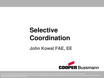
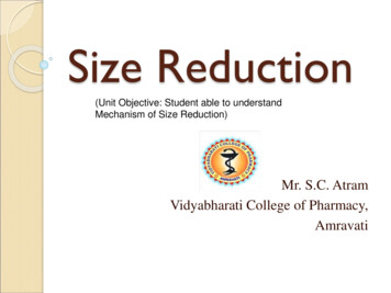
Chapter 1 – Selective Noncatalytic Reduction1. SELECTIVE NONCATALYTIC REDUCTION1.1IntroductionSelective noncatalytic reduction (SNCR) is a post combustion emissions controltechnology for reducing NOx by injecting an ammonia type reactant into the furnace at a properlydetermined location. This technology is often used for mitigating NOx emissions since it requiresa relatively low capital expense for installation, albeit with relatively higher operating costs.Japan originally developed SNCR for oil and gas units in the 1970s; Western Europe followedby applying the science to coal fired units in the late 1980s and the U.S electric power sectorbegan installations on coal plants in the early 1990s. More than 45 gigawatts of coal-fired powercapacity in the U.S. now have SNCR.1 SNCR is now used beyond the electric power industry,and is currently being used to control NOx emissions from a multitude of combustion sources,including industrial boilers, electric utility steam generators, thermal incinerators, cement kilns,pulp and paper power boilers, steel industry process units, refinery process units, and municipalsolid waste energy recovery facilities [1, 2, 3]. It is being used on industrial boilers covering awide range of sizes from 50 MMBtu/hr to more than 800 MMBtu/hr [2]. SNCR is also beingused on a wide range of sizes of utility boilers from 50 MW to more than 900 MW. More thanhalf of utility boilers with SNCR are relatively small ( 50 – 200 MW) but about 24 percent arelarger than 300 MW.1 Over 70 percent of the utility boilers using SNCR burn coal as the primaryfuel and most of the others burn biomass, but the other types of combustion sources are burning awide range of materials [2].1 SNCR can be applied as a standalone NOx control or with othertechnologies such as combustion controls. The SNCR system can be designed for seasonal oryear-round operations.Reported SNCR reduction efficiencies vary over a wide range. Temperature, residencetime, type of NOx reducing reagent, reagent injection rate, uncontrolled NOx level, distribution ofthe reagent in the flue gas, and CO and O2 concentrations all affect the reduction efficiency ofthe SNCR [2]. Tables 1.1 and 1.2 and Figures 1.1a, 1.1b, and 1.1c summarize emissionreductions for SNCR applications in a variety of industries [2]. Findings based on review ofthese data are as follows: 1Although installation of urea-based systems is more common than ammonia-baseddeployments, operating data reveal higher NOx reductions occur with ammonia reagent.Table 1.1 shows the median (as a measure of average) reductions for urea-based SNCRsystems in various industry source categories range from 25 to 60 percent, while medianreductions for ammonia-based SNCR systems range from 61 to 65 percent. Note thatmost of the boilers with ammonia-based SNCR systems that are fired with solid fuels arefired with wood or municipal solid waste. Figure 1.1b shows nearly all ammonia-basedsystems have reduction efficiencies greater than 40 percent, while several urea-basedsystems have lower reduction efficiencies.Spreadsheet of information provided to EPA's Clean Air Market Division from query of SNL Energy data on1/22/2015.1-1
Chapter 1 – Selective Noncatalytic ReductionTable 1.1: Summary of NOx Reduction Efficiencies Obtained Using SNCR on DifferentTypes of Boilers in the U.S. [2]Type of sourcecategoryNOxreductionreagentFuelAverage boilersizeMedian NOxreduction (%)Electric utilityCoalUrea320 MW25Co-generationPrimarily wood, some coal, biomass, andtiresUrea360 MMBtu/hr50Pulp & paper (P&P)Primarily bark and wood waste,supplemented with a variety of other fuelsUrea410 MMBtu/hr50Municipal wastecombustion (MWC)Municipal solid waste (MSW)Urea270 MMBtu/hr37Refinery CO boilersTypically refinery fuel gasUrea320 MMBtu/hr60Miscellaneouscombustion unitsPrimarily wood, MSW, or coalAmmonia400 MMBtu/hr65Miscellaneouscombustion unitsPrimarily crude oil or gasAmmonia110 MMBtu/hr61Table 1.2: SNCR NOx Reduction Efficiency by Industry and Reagent Type [2, 4]% ReductionIndustry and UnitsAmmonia-BasedUrea-BasedCement Kilns12-7725–90Chemical IndustryNAa35–80Circulating Fluidized and Bubbling Bed Boilers76–80NACoal, Wood and Tire Fired Industrial and IPP/Co-Generations BoilersNA20–75Coal-Fired Boilers38–8320–66Gas- and Oil-Fired Industrial Boilers30–75NAGlass Melting Furnaces51–70NASteel Products IndustryNA42.9–90Municipal Waste Combustors45-7016–87Oil- and Gas-Fired Heaters45–76NAProcess UnitsNA40–85Pulp and Paper IndustryNA20–62Refinery Process Units and Industrial BoilersNA20–75Stoker-Fired and Pulverized Coal-Fired Boilers50–83NAStoker-Fired Wood-Fueled Boilers40–75NAVapor, Sludge and Hazardous Waste Incinerators65–91NAaNAmeans not available.1-2
Chapter 1 – Selective Noncatalytic ReductionSNCR Reductions for Utility BoilersNOx Reduction Efficiency (%)Coal-fired ler size (MW)Figure 1.1a: SNCR NOx Reduction Efficiency for Various Utility Boiler Sizes [2]SNCR Reductions for Industrial BoilersNOx Reduction Efficiency (%)Various Industry Sectors100urea reagent: solid square, diamond,and triangular markersammonia reagent: " " and "x" markers80604020002004006008001000Boiler size (MMBtu/hr)P&P (bark & other wood fuel)Refineries (fuel gas fuel)Misc (various G/L fuels)MWC (MSW fuel)Misc (various solid fuels)Figure 1.1b: SNCR NOx Reduction Efficiency for Boilers in Various Industry Sectors [2]1-3
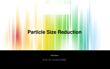
Chapter 1 – Selective Noncatalytic ReductionSNCR Reduction vs "Inlet" NOx Levelfor Coal-fired EGUs(Subset of all data)45NOx Reduction, %403530y 22.554x 16.725R² 0.4625201500.20.40.60.81Inlet NOx Emissions, lb/MMBtuFigure 1.1c: SNCR NOx Reduction Efficiency Versus Baseline NOx Levels for Coal-firedUtility Boilers [2] Figure 1.1a shows the efficiencies for utility boilers range from 20 percent to over60 percent with most between 20 percent and 35 percent. Figure 1.1a also shows theefficiencies for the larger utility boilers are comparable to those for smaller utility boilers. Although there is significant scatter, Figure 1.1c shows a trend of increasing reductionswith increasing baseline NOx levels for utility boilers. Specifically, the reductions rangefrom 20 percent when the baseline NOx concentration is about 0.2 lb/MMBtu to 35percent when the baseline NOx concentration is about 0.8 lb/MMBtu. This plot excludes4 data points that had baseline NOx concentration over 1 lb/MMBtu and 5 additional datapoints with reductions over 50 percent because such conditions are significantly outsidethe range of the other available data. Similar plots for boilers in other industry sourcecategories showed no trends. Data indicates average reductions for industrial boilers surpass average reductions forutility boilers (see Table 1.1, Fig. 1.1a, and Fig. 1.1b). Figure 1.1b shows reductions forindustrial boilers range from about 25 percent to 80 percent, which is a slightly higherrange than for coal-fired utility boilers in Figure 1.1a. Table 1.1 shows the medianreductions for industrial boilers equipped with urea-based SNCR in various industrysource categories range from 37 percent to 60 percent, while the median reduction forutility boilers is 25 percent.1-4
Chapter 1 – Selective Noncatalytic Reduction Table 1.2 presents the range of reductions for numerous source categories. It alsoincludes data for facilities outside the U.S. For most source categories, the range boundsare represented by facilities in the U.S. However, most of the reductions over 80 percentare for facilities outside the U.S. The only exception is the Steel Products Industry2 wherethe greatest reduction of 90 percent is at a U.S. facility.Factors such as the temperature, residence time, reagent distribution in the flue gas, andCO/O2 concentrations may be affected by the age, design, load variability, and capacity factor ofthe combustion unit. Fuel type and composition can also affect these parameters. However,information on these characteristics is not available for the units profiled in Tables 1.1 and 1.2and Figures 1.1a, 1.1b, and 1.1c. However, some SNCR systems are designed with reagentinjection ports at different locations to address changes in the temperature profile due changes infuel type and load.SNCR is only effective in a relatively high, narrow temperature range and therefore is notsuitable for all applications. The site-specific operating and design characteristics of the emissionunit must be evaluated on a case-by-case basis to determine whether SNCR is feasible. Severalfactors determine whether SNCR is an appropriate control for a source, including temperature,residence time, feasibility of installing reagent injection ports, and the NOx concentration. SNCRis not suitable for sources where the residence time is too short, temperatures are too low, NOxconcentrations are low, the reagent would contaminate the product, or no suitable location existsfor installing reagent injection ports. For example, SNCR is generally not used for gas turbinesbecause low NOx concentrations in the flue gas make SNCR less efficient than other availablecontrol methods [2]. Sources with stable temperatures of 1550oF to 1950oF, uncontrolled NOxemissions above 200 ppm, and residence times of 1 second are generally well suited to SNCRand attain the highest levels of NOx control.Available information from 7 Best Available Retrofit Technology (BART) analyses inwhich SNCR was designated as BART for 11 cement kilns indicates estimated NOx reductionsfor SNCR systems that are between 35 percent and 58 percent with a median reduction of 40percent [5]. Two of these kilns have proposed BART emission limits--one at 5.5 lb NOx/tonclinker and the other at 8.0 lb NOx/ton of clinker. Also, SNCR was determined as BART in 2014for a lime kiln in Arizona. NOx reductions of 50 percent were estimated for the SNCRapplication, and the final BART emission limits were 3.81 lb NOx/ton of clinker for one kiln andother at 2.61 lb NOx/ton of clinker for the other, with a combined limit of 3.27 lb NOx/ton ofclinker on a 30-day rolling average [6].For cement kilns, the kiln type, design, raw material composition, and the type of cementproduced impact uncontrolled NOx emissions rates. Kiln type and design also impact the degreeof difficulty encountered when installing SNCR injection systems on cement kilns. Preheater andprecalciner kilns are relatively simple SNCR installations. In preheater/precalciner kiln design,the SNCR injection ports can be installed in the combustion zone in the calciner, the oxidationzone of the upper air inlet before the deflection chamber, or in the area after the mixing chamberbefore the inlet to the bottom cyclone [7]. In the long wet and dry kiln designs, the appropriatetemperature window is in the middle of a kiln. Because of the rotating nature of a long kiln,2In the referenced study, this source category is called the “Industrial/Steel Industry”.1-5
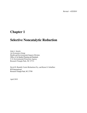
Chapter 1 – Selective Noncatalytic Reductioncontinuous injection of ammonia- or urea-based reagents is technically more difficult, and thetechnology developed for mid-kiln firing that allows injection of material once during each kilnrevolution was thought to be impractical for SNCR. However, tests on wet kilns in Franceshowed that injection of urea into long-wet kilns was possible if mixing is induced andvolatilization or decomposition of the urea is delayed by inserting it in a solid form in a carriersuch as tires [8]. According to one source, SNCR systems for long kilns may use one of twodesigns. The first requires the installation of a rotary valve at the feed end of the kiln and requirethe reagent piping to pass in and out of the kiln wall in order to reach the optimum temperaturezone within the rotating kiln. The second is the Cadence system, which consists of a manifoldfixed to the kiln with a small opening through which ammonia reagent is continuously fed at afixed rate [9].SNCR utilizes ammonia or urea as a NOx reduction reagent. An information collectionrequest for data from electric utilities indicated that based on 132 SNCR units, approximately67% (or 88 units) used urea and 33% (44 units) used ammonia; of those units listed as usingurea, 11 units indicated use of urea to ammonia conversion [10].The mechanical equipment associated with an SNCR system is simple compared to anSCR, semi-dry FGD, or wet scrubber and thereby requires lower capital costs ( /mmBtu/hrbasis). Installation of SNCR equipment requires minimum downtime. Although simple inconcept, it is challenging in practice to design an SNCR system that is reliable, economical, andsimple to control and that meets other technical, environmental, and regulatory criteria. Practicalapplication of SNCR is limited by the boiler design and operating conditions.The costing algorithms in this report are based on retrofit applications of SNCR toexisting coal-fired utility boilers [11]. In the 1990's there was little difference between the cost ofSNCR retrofit of an existing boiler and SNCR installation on a new boiler [12]. Over the yearsSNCR has begun to be applied to existing sites that are more difficult to retrofit which means thegap between average retrofit and new installation costs may be greater than it used to be, but it isnot expected to be substantial. Therefore, the cost estimating procedure in this report is suitablefor both retrofit and new boiler applications of SNCR on all types of coal-fired electric utilitiesand large industrial boilers. For other sources, this methodology is somewhat less applicable, andcalculations should be developed more specific to the source being controlled. The costmethodology incorporates certain approximations; consequently, it should be applied to developstudy-level accuracy ( -30%) cost estimates for SNCR applications.Based on applications in operation, capital costs for SNCR installations are generally lowdue to the small amount of capital equipment required, and the cost per unit of output decreasesas the size of the source increases. For example, Figure 1.2 shows the installed capital cost ofSNCR technology for industrial boilers, on a /MMBtu/hr basis, decreases as the size of theboiler (and therefore the gross heat input in MMBtu/hr) increases. In addition, the installedcapital cost of SNCR applications ranged from 4-44/kWe (kilowatt) for power generation unitsbased on data for 2005-2007 [13]. The installed cost represents the cost of the capital equipmentplus the associated installation expenses, but does not include the operation, maintenance, orreagent costs [1]. Table 1.3 contains a summary of average capital costs for SNCR applicationson various size units in several source categories.1-6
Chapter 1 – Selective Noncatalytic ReductionFor cement kilns, the capital costs for SNCR systems range from 1.5 to 2 million andare relatively consistent regardless of the type and production capacity of the kiln [9]. Because oftheir lower production capacities, the capital costs per ton of clinker produced are generallyhigher for long-wet and long-dry kilns than for preheater/precalciner kilns. One source reportedthe capital costs for precalciner kilns to be 1 to 2 per ton of clinker [9]. As for other emissionunits, SNCR operating costs for cement kilns vary by the desired level of uncontrolled NOxemissions. The higher the uncontrolled NOx emissions and lower the desired NOx outletemissions, the greater the quantity of reagent used and hence, higher the operating cost. The NOxemissions differ by kiln type, raw material composition, type of cement produced, fuel type, andfuel injection location [8].Most of the cost of using SNCR is operating expense. A typical breakdown of annualcosts for utilities is 25% for capital recovery and 75% for operating expense [2]. The primaryoperating expense is for the NOx reduction reagent. Thus, the total annual costs vary directlywith the NOx reduction requirements. For industrial boilers, typical cost effectiveness values forannual operation of SNCR are less than 3,000 per ton of NOx removed, and typical costeffectiveness values for ozone season operation are less than 4,000 per ton of NOx removed[1].3Figure 1.2: Actual SNCR Installed Capital Costs on Industrial SourcesUsed with permission from ICAC [1]3The cited study reported cost-effectiveness values for more than 30 boilers. However, the study did not report theyear to which costs were normalized or the applicable year dollars for the individual values.1-7
Chapter 1 – Selective Noncatalytic ReductionTable 1.3: Summary of SNCR Cost lCommercialBoilersPortlandCementUnit SizeNANACapital Cost:average (range)aFuel TypeCoalNA YearReferenceNA ( 10– 20/kW) [R]2005 b[14]NA ( 5- 20/kW)2008 b[2][15]NANANA ( 10- 30/kW)2006 bNANANA ( 4-44/KW)20052007[13] 100 MMBtu/hrNANA ( 900– 2,500/MMBtu/hror 9,000- 25,000/MW)2006 [16]21–844 MMBtu/hrNASee Figure 1.22006 b[2, 17][17]89–285 MMBtu/hrWoodNA ( 0.924– 1.786 million)2006 b 250 MMBtu/hrNANA ( 0.5- 1.0 million)2000 b[18]100–1,000 MMBtu/hrCoalNA ( 2,600– 5,300/MMBtu/hr) [R]1999 [19]100–1,000 MMBtu/hrGasNA ( 2,100– 4,200/MMBtu/hr) [R]1999 [19]100–1,000 MMBtu/hrOilNA ( 2,000– 4,100/MMBtu/hr) [R]1999 [19]350 MMBtu/hrGas and papersludgeNA ( 0.775 million) [N][ 0.50-0.75 million]e1997 [18]155 MMBtu/hrMediumDensityFiberboardwaste andwood wasteNA ( 0.24 million) [N]1996 [18]900 MMBtu/hrWoodNA ( 1.1 million)1999 b[18]475 MMBtu/hrWoodNA ( 0.70 million)1999 b[18]300 MMBtu/hrWoodNA ( 0.60 million)1999 b[18]245 MMBtu/hrWoodNA ( 0.39 million)1999 b[18]1.095 million shorttpy clinkerNANA ( 1.154 million or 1.05per short ton clinker) [N]2011 b[20]1.09 million short tpyclinkerNANA ( 2.3 million or 2.1 pershort ton clinker) [R]2006 b[8, 21]1.13 million short tpyclinkerNANA ( 2.3 million or 2.0 pershort ton clinker) [R]2006 b[8, 21]2.16 million short tpyclinkerNANA ( 2.3 million or 1.1 pershort ton clinker) [R]2006 b[8, 21]1.4 million short tpyclinkerNANA ( 1.153 million or 0.8per short ton clinker)2004 [22]NANANA ( 1.4 million) [N]2003 [23]1-8
Chapter 1 – Selective Noncatalytic ReductionSourceCategoryUnit SizeCapital Cost:average (range)aFuel Type YearReference 150 ton/hr(precalciner kiln)NANA ( 0.40– 0.80 million)e1999 b[18]100 ton/hr(precalciner kiln)NANA ( 0.08/ton clinker or 0.90 million)1994 b[18]0.3 million short tpyclinker (wet kiln)NANA ( 1.4 million or 4.7 pershort ton clinker) [R]2006 b[8, 24]0.320 million shorttpy clinker (wet kiln)NANA ( 1.2 million to 1.4million or 3.8 to 4.4 pershort ton clinker)2006 b[8, 21]PetroleumRefinery–ProcessHeater350 MMBtu/hrGas/refineryfuel gas orrefinery oilNA ( 0.706– 2.59 million)[R]d2004 c[25]PetroleumRefinery–Boiler650 MMBtu/hrGas or refineryfuel gasNA ( 1.31– 4.80 million)[R]d2004 c[25]Pulp andPaper–Boilers300,000 lb/hrWood orwood/coal/oilNA ( 1.5 million) [R]2004 b[14]aCosts are for both new SNCR and retrofit SNCR, unless otherwise noted. [R] indicates costs are for retrofit only.[N] indicates costs are for new only, NA indicates the data are not available.b Year of reference.c Year analysis was conducted (assumed vendor contacts were made that year).d Costs are for SNCR only, that is part of combination control including LNB plus SNCR.e Cost does not include installation cost; installation would add 20–30% to the cost shown here.1.2Process DescriptionThe basis of SNCR technology is a non-catalyzed chemical reaction utilizing an ammoniabased reagent (such as urea or ammonia) for reducing NOx into nitrogen (N2) and water (H2O) byinjecting this reagent into the post combustion gas stream at temperatures ranging from 16002400 F (870–1320 C) [26]. The reagent can react with a number of flue gas components.However, the NOx reduction reaction is favored over other chemical reaction processes for aspecific temperature range and in the presence of oxygen; therefore, it is considered a selectivechemical process.The conventional SNCR process occurs within the combustion unit, which acts as thereaction chamber. Figure 1.3 shows a conventional SNCR process schematic for an electricpower boiler with injection nozzles mounted through the wall and penetrating the combustionunit. The injection nozzles are located in the post-combustion area in the upper area of thefurnace near the convective passes. The injection causes mixing of the reagent and flue gas. Theheat of the boiler provides the energy for the reduction reaction. The NOx molecules are reducedand the reacted flue gas then passes out of the boiler. More details on the SNCR process andequipment are provided in the following sections.Single- and multi-level injection systems for SNCR installations can be effective for NOxreduction. Using different injector configurations can increase efficiency and reduce capital and1-9
Chapter 1 – Selective Noncatalytic Reductionoperating costs. Several new approaches are currently being used in addition to conventionalSNCR installations, including SNCR Trim, Rich Reagent Injection, NOxSTAR, and ROTAMIX.Figure 1.3: Boiler Gas Path Configuration1.2.1 Reduction ChemistrySNCR is a relatively simple chemical process. The process begins with an ammoniabased reagent, ammonia (NH3) or urea [CO(NH2)2], being vaporized either before injection by avaporizer or after injection by the heat of the boiler. Within the appropriate temperature range,the gas-phase urea or ammonia then decomposes into free radicals including NH3 and NH2. Aftera series of reactions, the ammonia radicals come into contact with the NOx and reduce it to N2and H2O.Since NOx includes both NO and NO2, the overall reactions with urea and ammonia areas follows:2NO 2NH3 1/2O2 2N2 3H2O(1.1a)2NO2 4NH3 O2 3N2 6H2O(1.1b)1-10
Chapter 1 – Selective Noncatalytic ReductionThe urea reaction equations for NO and NO2 are:2NO CO(NH2)2 1/2O2 2N2 CO2 2H2O(1.2a)2NO2 2CO(NH2)2 O2 3N2 2CO2 4H2O(1.2b)Equations 1.1a and 1.2a are the predominant reactions because the 90 to 95% of NOx influe gas from combustion units is NO. The reaction occurs as a two-step process in which theammonia reacts with available hydroxyl radicals to form amine radicals and water:NH3 OH NH2 H2OThe amine radicals combine with nitrogen oxides to form nitrogen and water [8]:NH2 NO N2 H2O”The primary byproduct formed in either ammonia- or urea-based SNCR systems isnitrous oxide (N2O). N2O is an ozone depleter and greenhouse gas.4 Urea-based reductiongenerates significantly more N2O than ammonia-based systems; up to 30% of the NOx can betransformed into N2O [12, 27]. In one study, N2O emissions were measured at 0 to 7 μmol/mol inammonia-based SNCR, and as high as 27.8 μmol/mol in urea-based SNCR [28]. The amount ofN2O formed depends on the reagent feed rate and temperature, and increased N2O formationcorrelates with increased NOx reductions [27, 29]. Proprietary additives are available for theurea-based SNCR process to reduce the formation of N2O [12].1.2.2 ReagentsReagent costs currently account for a large portion of the annual operating expensesassociated with this technology, and this portion has been growing over time. Ammonia isgenerally less expensive than urea since urea is derived from ammonia. However, the choice ofreagent is based not only on cost but also on physical properties and operational considerations.The properties of urea and ammonia in aqueous solutions are shown in Table 1.4.4EPA issued a final rule on November 29, 2013 as part of a notice of data availability concerning the MandatoryGreenhouse Gas Rule that indicates the global warming potential (GWP) of N 2O is 298. The November 29, 2013notice can be found in the Federal Register at 3-27996.pdf.1-11
Chapter 1 – Selective Noncatalytic ReductionTable 1.4: Urea and Ammonia Reagent Properties [30]PropertyUrea SolutionAqueous AmmoniaChemical formulaCO(NH2)2NH3Molecular Weight of reagent60.0617.03Liquid or gas at normal airtemperatureLiquidLiquidConcentration of reagent normallysupplied50% by weight19.0% by weightRatio of NH3 to solution28.3% by weight of NH319.0% by weight of NH3lb/ft358 lb/ft3(56 lb/ft3 for 29.4%)Density of solution @ 60 F71Vapor pressure @ 80 F 1 psia14.8 psia [31]Crystallization temperature64 F 110 FFlammability limits in airNon-flammableLower explosion limit 16% NH3by volumeUpper explosion limit 25% NH3by volume.Threshold limit value (healtheffects)Not specified25 ppmOdorSlight (ammonia-like)Pungent odor @ 5 ppm or moreAcceptable materials for storagePlastic, steel, or stainless steel (nocopper or copper- based alloys orzinc/aluminum fittings)Steel tank, capable of handling atleast 25 psig pressure (no copperor copper-based alloys, etc.)Ammonia can be supplied in either aqueous or anhydrous form. Anhydrous ammonia is agas at normal atmospheric temperature and must be transported and stored under pressure, whichpresents safety issues and increases transportation cost [26]. Aqueous ammonia is generallytransported and stored at a concentration of 29.4% ammonia in water. At concentrations above28%, storage of ammonia may require a permit; therefore, some applications of SNCR useaqueous ammonia solutions of 19% [32]. For example, most U.S. cement plants use a solution of19-20% aqueous ammonia reagent, while some cement plants in Europe use 25% ammoniasolutions [8, 33]. Decreasing the concentration, however, increases the required storage volumeand associated transportation costs. Ammonia may be injected either as a vapor or as an aqueoussolution. Providing sufficient ammonia vapor to the injectors requires a vaporizer, even thoughthe 29.4% solution has substantial vapor pressure at normal air temperatures. The injectionsystem equipment for vapor systems is more complicated and expensive than equipment foraqueous systems (see Section 1.2.4, SNCR System).Urea is generally stored in a 50% aqueous solution [2, 32]. At this concentration, the ureasolution must be heated and circulated in cold climates due to its low freezing point, 64 F(18 C). Higher concentrations of urea solutions are available that decrease the storage volumebut require extensive heating to prevent freezing. Urea is injected into the boiler as an aqueoussolution and vaporized by the heat of the boiler. Urea can also be transported in pellet form,which minimizes transportation requirements, or can be transported at a higher concentration,which reduces the transportation cost due to the lower weight and volume of the solution.However, to produce aqueous urea for use in the SNCR system, the urea must then be mixedwith water at the facility to dilute it to the 50% aqueous solution [26]. For urea pellets, thisdissolving, diluting, and mixing process is generally cost prohibitive except for remote sites,1-12
Chapter 1 – Selective Noncatalytic Reductionlarge facilities, or facilities where chemical mixing processes are already being performed, due
larger than 300 MW.1 Over 70 percent of the utility boilers using SNCR burn coal as the primary fuel and most of the others burn biomass, but the other types of combustion sources are burning a wide range of materials [2].1 SNCR can be applied as a standalone NO x control or with other technologies such as combustion controls.