Transcription
SelectiveCoordinationJohn Kowal FAE, EENational Electrical Code and NEC are registered trademarks of the National Fire Protection Association (NFPA), Inc., Quincy, MA02269. This presentation does not reflect the official position of the NFPA.Great care has been taken to assure the recommendations herein are in accordance with the NEC and sound engineering principles. Cooper Bussmann cannot take responsibility for errors or omissions that may exist. The responsibility forcompliance with the regulatory standards lies with the end user.
Course Outline Definition of Selective Coordination– Guiding Code Requirements Why is Selective Coordination Important Which Overcurrent Devices Need to BeSelectively Coordinated?– How to Selectively Coordinate with Fuses?– How to Selectively Coordinate with Circuit Breakers? How to Comply with Selective Coordination– Analysis Methods– OCPD Choices & Trade-Offs Myths About Selective Coordination Compliance Process 2009Cooper Bussmann2
What is SelectiveCoordination?
Selective Coordination Requirements1993 NEC Articles 620 Elevator Circuits2005 NEC Articles 700 Emergency Systems 701 Legally Required Standby Systems 517 Healthcare Facilities2008 NEC Articles 708 Critical Operations Power Systems 2009Cooper Bussmann4
Guiding Code RequirementsSelective Coordination requirements 2008/2011 NEC 100Definition: Coordination Selective (2005-11)517.26 Required for Essential Electrical Systems (2005-11)620.62 Required for Circuits with multiple Elevators (1993)700.9(B)(5)(b) Exception. OCPDs permitted at alternate sourceor for equipment (2008) 700.27 Required for Emergency Systems (2005,2008,2011) 701.27 Required for Legally Required Standby Systems(2005,2008,2011) 708.54 Required for Critical Operations Power Systems(COPS) (2008-11) 2009Cooper Bussmann5
Definition Selective Coordination is Defined byNEC Article 100 Definitions:Coordination (Selective)– Localization of an overcurrent conditionto restrict outages to the circuit orequipment affected, accomplished bythe choice of overcurrent protectivedevices and their ratings or settings. 2009Cooper Bussmann6
What is Selective Coordination For the full range ofpossible overcurrents Only closest upstreamOCPD fromovercurrent opens Other upstream(larger) overcurrentprotective devices donot open 2009Cooper BussmannLINE SIDELOAD SIDEKRP-C-1200SPLPS-RK-600SP7
ExampleWithout Selective CoordinationWith Selective CoordinationOPENSOPENSFaultNOTAFFECTEDFaultNOT AFFECTED 2009Cooper BussmannUNNECESSARYPOWER LOSS8
Why is SelectiveCoordinationImportant?
Why is Selective Coordination Important?Answer: Increases system reliability to deliverpower Focus on the load!Availability of power to vital loads aslong as possible Life Safety Public safety and national security–By maintaining Critical Operations andPower Systems (COPS) Increases system reliability to powervital loads even during emergenciesand disasters Facilitates restoration of power toaffected loads 2009Cooper BussmannFaultOPENSNOT AFFECTED10
NEC Requires Selective CoordinationArticle 700 Emergency Systems 700.27 Coordination– includes 517 healthcare essential electrical systems Emergency system(s) overcurrent devices shallbe selectively coordinated with all supply sideovercurrent protective devices– Two exceptions apply for 700.27 and 701.27– Wording for 701.27 and 708.54 is the similar except forthe type system 2009Cooper Bussmann11
Which OvercurrentDevices Need to BeSelectivelyCoordinated?
Selective CoordinationWhich Overcurrent Devices Need to BeSelectively Coordinated?Answer: All Overcurrent Devices 2009Cooper BussmannRequired for Circuits with multiple Elevators (1993)Required for Essential Electrical Systems (2005)Required for Emergency Systems (2005)Required for Legally Required Standby Systems (2005)Required for Critical Operations Power Systems (COPS) (2008)13
Selective CoordinationWhich Overcurrent Devices Need to BeSelectively Coordinated?Answer: All Overcurrent Devices 2009Cooper BussmannRequired for Circuits with multiple Elevators (1993)Required for Essential Electrical Systems (2005)Required for Emergency Systems (2005)Required for Legally Required Standby Systems (2005)Required for Critical Operations Power Systems (COPS) (2008)14
Emergency SystemsNEC 700.27 Coordination. Emergency system(s)overcurrent devices shallbe selectively coordinatedwith all supply sideovercurrent protectivedevicesQuestion: Which “overcurrentdevices”are emergencysystem overcurrentdevices in this system? 2009Cooper BussmannNormalSourceEmergencySourceNEATSPanel15
Emergency SystemsNEC 700.27 Coordination. Emergency system(s)overcurrent devices shallbe selectively coordinatedwith all supply sideovercurrent protectivedevicesAnswer: ALL overcurrent deviceson the load side of theemergency source areemergency systemovercurrent ency system overcurrent devices 2009Cooper Bussmann16
Emergency SystemsNEC 700.27 Coordination. Emergency system(s)overcurrent devices shallbe selectively coordinatedwith all supply sideovercurrent protectivedevicesQuestion: Which are overcurrentprotective devices in thenormal source path thatsupply the emergencysystem? 2009Cooper BussmannNormalSourceEmergencySourceNEATSPanel17
Emergency SystemsNEC 700.27 Coordination. Emergency system(s)overcurrent devices shallbe selectively coordinatedwith all supply sideovercurrent mergency system overcurrent devicesNormal system overcurrent devices thatare supply side overcurrent devices foremergency system overcurrent devicesPanelNormal system overcurrent devices 2009Cooper Bussmann18
Emergency SystemsNEC 700.27 Coordination. Emergency system(s)overcurrent devices shall beselectively coordinated with allsupply side overcurrentprotective devicesAnswer: Red-striped emergency systemovercurrent devices mustselectively coordinate with allblue-striped supply side normalsystem overcurrent protectivedevices as required in ncy system overcurrent devicesNormal system overcurrent devices thatare supply side overcurrent devices foremergency system overcurrent devices 2009Cooper Bussmann19
Emergency Systems700.27 “Emergency system(s) overcurrent devicesshall be selectively coordinated with all supply sideovercurrent protective devices”This wording is inclusive of the alternate path andnormal source path overcurrent devices for eachemergency load.EmergencySourceNormalSource6Practical Application Requirement Example: 1 must selectively coordinate with 2, 3, 4, 5, 6435NEATS 2 must selectively coordinate with 3, 4, 5, 6 3 must selectively coordinate with 42 Does 5 have to be selectively coordinate with 6?–By the strict wording of the requirements, 5 does not have toselectively coordinate with 6 because neither device is part ofthe emergency system–However, The wise decision is to be sure that 5 selectivelycoordinates with 6, even though t is not specifically required by700.27. 2009Cooper BussmannNotation method: 1 represents OCPD device 11Panel20
700.27 & 701.18 ExceptionsHashed OCPDs do not have to be selectively coordinatedException 1:Exception 2:Transformer primary andTwo devices ofsecondarysame amp rating inseries400A OCPDSameCircuitSameCircuit 2009Cooper BussmannNeither exception reduced life-safetybecause no additional parts of theelectrical system would be shut downunnecessarily400A OCPD21
How to SelectivelyCoordinate withFuses?
How to Selectively Coordinate with Fuses?Answer:Simply Follow the Fuse Manufacturer’sSelectivity RatioIt is That Simple!! 2009Cooper Bussmann23
Fuse Selectivity Ratio Tables Each fuse manufacturer has conducted fusetesting and analysis to develop a simple fusetype/ampere ratio method to select fuses that areselectively coordinated Includes all overcurrent levels up to the fuses’interrupting ratings (up to 200KA) Based on:– Fuse types lineside and loadside– Meeting at least minimum ampere rating ratiolineside/loadside fuses 2009Cooper Bussmannbetween24
Selective Coordination(2005 SPD p 91 & 102)Line Side FuseLoad Side FuseNo plotting required! 2009Cooper BussmannLOW-PEAK : LOW-PEAK 2:1 Line:Load Ratio25
Fuse Selectivity Ratio Example 1Low-Peak KRP-C-800SPLow-Peak LPJ-400SPLow-Peak LPJ-100SP 2009Cooper BussmannOverloads or faultsof any level up to200,000ALoadside FuseKRP-C SPLPJ SPKRP-C SP2:12:1LPJ SP-2:1400/100 4:1 only 2:1 neededSelective Coordination achievedbetween these two fuses26
Fuse Selectivity Ratio Example 1Circuit Path SelectivelyCoordinatedLoadside FuseLow-Peak KRP-C-800SPLow-PeakLPJ-400SPLow-PeakLPJ-100SP 2009Cooper BussmannOverloads or faultsof any level up to200,000AKRP-C SP LPJ SPKRP-C SP2:12:12:1LPJ SP-2:1800/400 2:1 only 2:1 neededSelective Coordination achieved400/100 4:1 only 2:1 neededSelective Coordination achievedbetween these two fuses27
Fuse Selectivity Ratio Example 2 What about branch circuit lightingpanel applications?Low-PeakKRP-C-800SPLow-PeakLPJ-200SP Use the Quik-Spec Panel whichhas Class J TCF fuse branchcircuit protection: 1A to 100ALow-PeakCCP-20CFTCF20 fuse 2009Cooper BussmannCCP-20CF28
CB Feeding Fuse Selectively Coordinated? Can not determine by timecurrent curves for Iscagreater than point of arrow Only way to determine istesting of combination No known testing 2009Cooper Bussmann29
Fuse Feeding CB Selectively Coordinated? Selectively coordinate upto current where fusecurve intersects with CB This represents afuse/circuit breakerseries rated combination 2009Cooper Bussmann30
How to SelectivelyCoordinate with CircuitBreakers?
How to Selectively Coordinate with Circuit Breakers?Answer:Do short-circuit current study andcoordination study investigating various typesand options of CBs for a specific project 2009Cooper Bussmann32
Circuit Breaker AlternativesCircuit Breaker ManufacturerCircuit Breaker Options (next slides)1. Instantaneous trip (IT)2. Instantaneous trip, coordination tablesCircuit Breaker TypeMCCBICCBLVPCB3. Fixed high magnetic IT4. Short time delay (STD) w/ IT override(MCCB/ICCB)5. Short time delay (STD) w/o IT override(LVPCB)Note: some options may require larger frameor different type CBsFault Current Available 2009Cooper Bussmann33
Thermal Magnetic CBAdjustable Instantaneous Trip CBAllow adjustment of theinstantaneous trip settingTypically 5 to 12 times theampere ratingFigure shows 100A CB Setting of 5X 500Aor Setting of 10X 1000A 2009Cooper Bussmann10X5X34
1. Circuit Breaker Instantaneous Trip2CURRENT IN AMPERES AT 480 VOLTS3 4 5 6 7 8 9 1002 3 4 5 6 7 8 9 1000 2 3 4 5 6 7 8 9 10000 23 4 5 67700700800AIT 10X500400300800A200AX30AX 2009Cooper 04.03.02.02.01Up to1500A50040030020.1Up to7600A200AIT 10X70TIME IN SECONDSUp to where the circuitbreakers cross, it isinterpreted to becoordinated. See1000TIME IN SECONDS10004 5 6 7 8 9 100.01s4 5 6 7 8 9 1023 4 5 6 7 8 9 10023 4 5 6 7 8 9 1000 23 4 5 6 7 8 9 10000 23 4 5 67.01CURRENT IN AMPERES AT 480 VOLTS1500A7600A35
2. CB Manufacturer’sSelective Coordination TableTable illustrates the selection of molded case CBsto achieve selective coordination 2009Cooper Bussmann36
2. CB Manufacturer’sSelective Coordination TableExample:30A & 200A MCCBs1500A Crossing PointInterpreting CurvesMax. 2700A: CB Mfg.Coordination Testing2CURRENT IN AMPERES AT 480 VOLTS3 4 5 6 7 8 9 100 2 3 4 5 6 7 8 9 1000 2 3 4 5 6 7 89 10000 23 4 5 IME IN SECONDSCB Manufacturer’sCoordination Tables canhelp show coordination forhigher fault current thansimply plotting curves4 5 6 7 89 .010.01s4 5 6 7 89 10TIME IN SECONDS100023 4 5 6 7 8 9 10023 4 5 6 7 8 9 1000 23 4 5 6 7 89 10000 23 4 5 67.01CURRENT IN AMPERES AT 480 VOLTS 2009Cooper Bussmann37
3. CoordinationFixed High Magnetic CB10004 5 6 7 8 9 102CURRENT IN AMPERES AT 480 VOLTS3 4 5 6 7 8 9 100 2 3 4 5 6 7 8 9 1000 2 3 4 5 6 7 8 9 10000 23 4 5 677001500A crossing pointstandard adjustable IT CB3200A crossing pointfixed high magnetic CB 2009Cooper 0.1s.1.07.07.05.04.03.05.04.03.02.02.010.01s4 5 6 7 8 9 10TIME IN SECONDS200A504030TIME IN SECONDSThe 200A CB is a fixedhigh magneticinstantaneous trip (IT)device. It will coordinatewith the downstream 30ACB up to 3200A versus1500A for a conventional200A CB.100023 4 5 6 7 8 9 10023 4 5 6 7 8 9 1000 23 4 5 6 7 8 9 10000 23 4 5 67.01CURRENT IN AMPERES AT 480 VOLTS38
4. CoordinationSTD with IT Override10004 5 6 7 89 102CURRENT IN AMPERES AT 480 VOLTS3 4 5 6 7 8 9 100 2 3 4 5 6 7 8 9 1000 2 3 4 5 6 7 89 10000 23 4 5 67700700800A500400300 Short-timedelay from2,400A to 6,400A providescoordination NotCoordinated in shortcircuit region above 6,400Adue to instantaneous A5435432211.7.7.5.4.3.5.4.3.2.2.1TIME IN SECONDScase CB withshort-time delay (STD) andinstantaneous trip override(protects CB)500400300200TIME IN SECONDS 010.01s4 5 6 7 89 1023 4 5 6 7 8 9 10023 4 5 6 7 8 9 1000 23 4 5 6 7 89 10000 23 4 5 67.01CURRENT IN AMPERES AT 480 VOLTS 2009Cooper Bussmann2005 SPD p996400A39
Simple CB Analysis MethodFor circuit breakers having instantaneous trips, there isa simple method to determine the highest short-circuitcurrent or short-circuit amps (Isca) at which CBs willselectively coordinateThere is no need to plot the curvesThis method is applicable to the instantaneous trip only,not the overload element. This can be used as a firsttest in assessing if a system is selectively coordinatedThere may be other means to determine higher valuesof Isca where CBs selectively coordinate (such asmanufacture’s tables), but this is a practical, easymethod 2009Cooper Bussmann40
CB Simple Analysis MethodInformation needed for each feeder and main CB:1. CBs amp ratings or amp settings2. CBs instantaneous trip settings (IT)– Most feeder and main CBs have adjustable ITsettings: there are various ranges from 4 to 12X– Some CBs have fixed settings Some newer feeder CBs have fixed IT set at 20X3. CBs IT percentage (%) tolerance– If CB IT % tolerance not known, here are someworst case* practical rules of thumb: Thermal Mag. (High Trip Setting): 20% Thermal Mag. (Low Trip Setting): 25% Electronic Trip Style: 10% 2009Cooper Bussmann* based on numerous samples taken from leading manufacturers41
CB Simple Analysis MethodEquation:Isca Coord (CB amp rating x IT setting) x (1 - % tolerance* )100Example: 200A CB with IT set at 10X and 20% toleranceIsca Coord (200 x 10) x (1 - 20% )100Isca Coord (2000)x (1 - 0.20) 2000A x 0.8Isca Coord 1600Asee graph on next slideResult: For currents up to 1600A, the 200A CB will selectivelycoordinate with the downstream CBs in the instantaneous operationNote 1: This does not consider the overload operation, but is a first test. If this testis successful, investigate the overload element coordinationNote 2: The tolerance is , however, for this simple method, only need to considerthe – tolerance 2009Cooper Bussmann* Best to use actual CB % tolerance, otherwise use assumed worst case % tolerance42
Simple Analysis MethodExample: 200A Thermal Magnetic MCCB1023 4 5 6 7 8 9 1002CURRENT IN AMPERES AT 480 VOLTS3 4 5 6 7 8 9 1000 2 3 4 5 6 7 8 9 10000 23 4 5 6 7 8 9 1000001023 4 5 6 7 8 9 1002CURRENT IN AMPERES AT 480 VOLTS3 4 5 6 7 8 9 1000 2 3 4 5 6 7 8 9 10000 23 4 5 6 7 8 9 1077710070TIME IN SECONDS504030This is forIT 5X543254321HighIT 10X(2000A)200100705040307This isexample fromprior slide54321000543211.7.7.5.4.3.5.4.3.2.2.2.2 25%.7.5.4.31 05.04.03.05.04.03.02.02.02.02.01.01.011023 4 5 6 7 8 9 10023 4 5 6 7 8 9 1000 23 4 5 6 7 8 9 10000 2CURRENT IN AMPERES AT 480 VOLTS 2009Cooper Bussmann750A1250A3 4 5 6 7 8 9 1000001023 4 5 6 7 8 9 10023 4 5 6 7 8 9 1000 23 4 5 6 7 8 9 10000 23 4 5 6 7 8 9 100000.01CURRENT IN AMPERES AT 480 VOLTS1600A2400A43TIME IN SECONDSLowIT 5X(1000A)200TIME IN SECONDS1000TIME IN SECONDS1000
Simple Analysis Method Ex. 12CURRENT IN AMPERES AT 480 VOLTS3 4 5 6 7 8 9 1002 3 4 5 6 7 8 9 1000 2 3 4 5 6 7 8 9 10000 27003 4 5 67700800AIT 10X500400300200100500400300200100200AIT 10X7050403070504030202010107754354322800A IT 10X Electronic ( 10%)Isca Coord (800x10) x (1-0.10) 7200A11.7.7.5.4.3.5.4.330A.2XX.2200A IT 10X Magnetic ( 20%)Isca Coord (200x10) x (1-0.20) 1600A30A 2009Cooper Bussmann1000.1.1.07.07.05.04.03.05.04.03.02.02.014 5 6 7 8 9 1023 4 5 6 7 8 9 10023 4 5 6 7 8 9 1000 23 4 5 6 7 8 9 10000 23 4 5 67.01CURRENT IN AMPERES AT 480 VOLTS1600A7200A44TIME IN SECONDS1000TIME IN SECONDS Look at CB settings andassess whether CBs arecoordinated No need to draw curves Assume tolerances shown4 5 6 7 8 9 10
Simple Analysis Method Ex. 22CURRENT IN AMPERES AT 480 VOLTS3 4 5 6 7 8 9 1002 3 4 5 6 7 8 9 1000 2 3 4 5 6 7 8 9 10000 23 4 5 67800AIT 10X200AIT 0403020201010775435432211.7.7.5.4.3.5.4.3Isca Coord (800x10) x (1-0.20) 6400A30A.2XX.2200A IT 10X Magnetic ( 20%)Isca Coord (200x10 x (1-0.20) 1600A30A 2009Cooper Bussmann1000.1.1.07.07.05.04.03.05.04.03.02.02.014 5 6 7 8 9 1023 4 5 6 7 8 9 10023 4 5 6 7 8 9 1000 23 4 5 6 7 8 9 10000 23 4 5 67.01CURRENT IN AMPERES AT 480 VOLTS1600A6400A45TIME IN SECONDS800A IT 10X Magnetic ( 20%)1000TIME IN SECONDS Look at CB settings andassess whether CBs arecoordinated No need to draw curves Assume tolerance shown4 5 6 7 8 9 10
Simple Analysis MethodUse Simple Rule for CBCircuit PathCoordination Analysis1000 A. MCCBIT @ 6 X ? A 10% Tolerance(see next slide)400 A. MCCBIT @ 10X ? A 20% ToleranceCoordinates to whatfeeder fault level ?X100 A. MCCBIT Non-Adjustable 2009Cooper BussmannXCoordinates to whatbranch fault level ?46
Simple Analysis MethodExample: Instantaneoustrip settings andtolerances known4 5 6 7 8 9 102CURRENT IN AMPERES AT 480 VOLTS3 4 5 6 7 8 9 1002 3 4 5 6 7 8 9 1000 2 3 4 5 6 7 8 9 10000 23 4 5 671000AIT 6X700500400300200700500400300200400AIT 10X1001007070504030504030202010TIME IN rance*Coord.Up To1000A6X 3.05.04.03.02.02400A100A10X 20%3,200.014 5 6 7 8 9 10* Suggest using specific CB tolerance, if notknown, use worst case % tolerance 2009Cooper Bussmann23 4 5 6 7 8 9 10023 4 5 6 7 8 9 1000 23 4 5 6 7 8 9 10000 23 4 5 67TIME IN SECONDS1000.01CURRENT IN AMPERES AT 480 VOLTS3200A5400A47
Simple Analysis MethodResults fromSimple AnalysisMethod1000 A. MCCBIT @ 6 X ? A 10% Tolerance(see previous slide)400 A. MCCBIT @ 10X ? A 20% ToleranceCoordinates to whatfeeder fault level 5400AX100 A. MCCBIT Non-Adjustable 2009Cooper BussmannXCoordinates to whatbranch fault level 3200A48
5. Short-Time Delay(No Instantaneous Trip Override)10003 4 5 6 7 89 1002CURRENT IN AMPERES AT 480 VOLTS3 4 5 6 7 8 9 1000 2 3 4 5 6 7 8 9 10000 23 4 5 6 7 89 10.01s1023 4 5 6 7 89 100TIME IN SECONDSStill need to plot curves toensure there is nocrossing of circuit breakercurves. Must have timesettings with enoughseparation.2700TIME IN SECONDSSelective coordination forall overcurrents up to theinterrupting rating for eachcircuit breaker1023 4 5 6 7 8 9 1000 23 4 5 6 7 8 9 10000 23 4 5 6 7 89 100000.01CURRENT IN AMPERES AT 480 VOLTS 2009Cooper Bussmann49
Circuit Breaker Choices Options and settings vary between CB Vendors Wide range of interrupting ratings (many models) MCCBs, ICCBs, LVPCBs– Different options available for each type– Different range of settings available Tested coordination tables for some CB to CBcombinations Use larger frame or more sophisticated CBs to achieveselective coordination for higher available fault currentsResult: May be trial and error working between themanufacturer’s specs and commercial softwarecoordination module Size and cost of equipment can increase Contractor has to spend the time ensuring the propertype CBs and options are installed and set correctly. 2009Cooper Bussmann50
How to Comply withSelectiveCoordination
How to Comply Analysis Methods OCPD Choices & Trade-Offs 2009Cooper Bussmann52
Analysis Methods Fuses– Use Selectivity Ratios LVPCBs– Short-Time Delay settings on feeders and main:sufficient separation– May need to plot curves (commercial package) CBs with instantaneous trip settings– CB manufacturer’s Coordination tables– Simple rules Isca must not exceed each CB amp rating X IT setting(include tolerance factor)– Use commercial software packages and interpretproperly 2009Cooper Bussmann53
Summary OCPD tionsNeededEase ofCoordinationAnalysisApplicability toSystemsDepending onAvailable ShortCircuit CurrentsCostOCPDMaintenance toEnsure Integrity 2009Cooper BussmannNoSimplestUse RatiosInstantaneousTripYesFix HighMagneticInstantaneousTripYesShort-TimeDelay WithInstantaneousOverrideYesTakes More Work (use one of below):Use CB Manufacturers’ Coordination TablesUse Simple Analysis RulesUse Commercial Software Packages: InterpretProperlyAllSome(where Iscalower)(larger frameCBs may help)Low toMediumNoLVPCBsShort-Time DelaySettings(STD)No(except forInterrupting Rating)SimpleProper Settings ofShort-Time DelayBandsMany(expandsapplicability)Some(where Iscalower)(larger frameCBs may help)All(limited toInterrupting Rating)Low to MediumLow to MediumLow to MediumHighYesYesYesYes54
Myths AboutSelectiveCoordination
Level of Fault CurrentMyth: Bolted short-circuits or high level fault currents don’toccur very frequently, so selective coordinationshould only be required for overload conditionsFact: Bolted faults are not the only condition where higherfault currents can result Low impedance short-circuits (results in high faultcurrent) can and do occur Higher level faults are more likely in fires, naturalcatastrophes, human caused catastrophes and otheremergency situations 2009Cooper Bussmann56
Arc Flash HazardMyth: Selective coordinationresults in an increased arc flashhazardFact: Lack of selectivecoordination can increase thearc flash hazard for electricalworkers Typically higher flash hazardcloser to the service If OCPDs unnecessarilycascade open, the electricworker must unnecessarilywork at higher levels in thesystem 2009Cooper ranch Panels57
Equipment ProtectionMyth: Selective coordination results in greater equipmentshort-circuit damage when short-time delay is usedFact: Equipment is now available with longer short-timewithstand ratings (short-circuit current rating) With CBs, zone selective interlocking allows theupstream CB to open as quickly as possible,bypassing the short-time delay for all faults betweenthe two CBs With current-limiting fuses, intentional short-time delayis not required for selective coordination. Therefore,short-circuits are taken off-line as quickly as possible;equipment damage is not increased. 2009Cooper Bussmann58
Compliance Process
Selective CoordinationEnsuring ComplianceRequiresproper engineering,specification andinstallation 2009Cooper Bussmann60
Selective CoordinationEnsuring ComplianceEngineer designs required systems to achieve selectivecoordination Selection of proper overcurrent protective devicesand Provide proper documentation verifying selectivecoordination 2009Cooper Bussmann61
Selective CoordinationEnsuring ComplianceContractor Install overcurrent protection as specified Substitutions must be approved by designer andmust be proven to meet requirements 2009Cooper Bussmann62
ComplianceWhere to get assistance for CBs CB manufacturers have published documents onhow to coordinate circuit breakers 2009Cooper Bussmann63
Questions?
Question 1A fault occurs on a motor branch circuitand both the branch circuit and feederovercurrent protective devices open.Are the branch circuit andfeeder overcurrent protective devicesselectively coordinatedwith each other?Yes or NoFaultUnnecessary outageOPENS 2009Cooper BussmannNOT AFFECTEDUnnecessaryPower Loss65
Question 2A fault occurs on a feederand the feeder and mainovercurrent protectivedevices open.FaultAre the feeder and main overcurrentprotective devices selectivelycoordinatedin this case?Yes or NoOPENS 2009Cooper BussmannNOT AFFECTEDUnnecessaryPower LossProperly Affected66
Question 4Selective coordination of overcurrent protective devices isrequired for emergency systems and legally requiredstandby systems per sections:A. 700.56 & 701.37B. 700.27 & 701.18C. 240.10 & 240.27D. 800.45 & 800.46 2009Cooper Bussmann67
Question 5In healthcare facilities, overcurrent protectivedevices are required to be selectivelycoordinated for critical branch, life safetybranch, and equipment systems essential forlife safetyTrueorFalse 2009Cooper Bussmann68
Question 6With fusible systems, selective coordination can bedesigned by adhering to the fuse selectivity ratios.Curves and detailed analysis are not typically required ifthe ratio are met.TrueorFalse 2009Cooper Bussmann69
Question 7With circuit breaker systems, selective coordination cantypically be designed in. It may require the use ofspecific types of circuit breakers with specific optionsand settings, short circuit current study and acoordination analysis of the circuit paths.TrueorFalse 2009Cooper Bussmann70
Question 50SPOverloads or faultsof any level up to200,000A 2009Cooper BussmannLoadside FuseKRP-C SP LPJ SP LPS-RK SPKRP-C SP2:12:12:1LPJ SP-2:12:1Is this a selectively coordinatedcircuit path?Yes or No71
Question -20Overloads or faultsof any level up to200,000A 2009Cooper BussmannLoadside FuseKRP-C SP LPJ SP LPS-RK SPKRP-C SP2:12:12:1LPJ SP-2:12:1Is this a selectively coordinatedcircuit path?Yes or No72
Question 10800A CBSTD @ 0.1 SecondsIs this a selectively coordinatedcircuit path?Yes or NoCURRENT IN AMPERES1000100A CBIT Non AdjustableMaximum fault currentat 20A circuit breakeris 800A1TIME IN SECONDS1020A CBIT Non Adjustable800 A w/ STD100100 A20 A0.10900A0.011101001K10K100Kdteate.tcc Ref. Voltage: 480 Current Scale x10 0 2009Cooper Bussmann73
Question 11800A CBSTD @ 0.1 SecondsIs this a selectivelycoordinated circuit path?Yes or NoCURRENT IN AMPERES1000100A CBIT Non AdjustableMaximum fault currentat 20A circuit breakeris 2500A 2009Cooper Bussmann1TIME IN SECONDS1020A CBIT Non Adjustable800 A w/ STD100100 A20 A0.10900A0.011101001K10K100Kdteate.tcc Ref. Voltage: 480 Current Scale x10 074
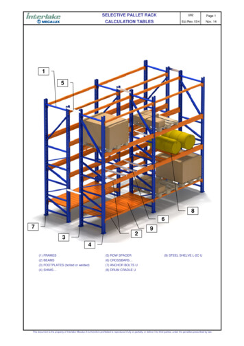
AlternateSourceNormalSourcePringle SwitchClass L FusesBussmannFusibleDisconnectEatonSquare D QED-2/QMBNGE Spectra FusibleClass RK1, J FusesEATSEFJ SeriesClass JFusesBussmannQuik-SpecCoordinationPanelboardClass JFusesScenario 1
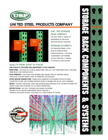
AlternateSourceNormalSourcePringle SwitchClass L FusesEatonNSquare D QED-2/QMBEATSGE Spectra Fusible60 ampClass RK1, J k-SpecCoordinationPanelboardClass JFusesScenario 2Panel30 ampPanelboardClass JFuses
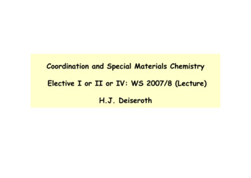
AlternateSourceNormalSourcePringle SwitchClass L FusesEatonSquare D QED-2/QMBNGE Spectra FusibleEATSClass RK1, JBussmann60A/3PMain30 A/3PQuik-SpecCoordination100A/Main30 A/3P15 KVAPanelboardClass J15 KVA60A/3PPanelDifficult to Coordinate!Are these lighting Loads?30 amp/3PPanel60A/3PMain30 A/3PAre there other loads?Can it be 480/277?Scenario 3
2009Cooper Bussmann78
2009Cooper Bussmann79
Quik-Spec Coordination PanelboardSingle “QSCP” Part Number600Vac / 400A with fusible andnon-fusible main or MLO18, 30 & 42 Branch circuitpositions with spaceoptions available50kA, 100kA & 200kA SCCRLoad Side Disconnect AvailableFinger-safe CUBEFuse CCPBfor branch circuit protectionIsolated or non-isolated groundoption200A or 400A Neutral optionUp to 100A branch circuitswith 1-, 2- and 3-pole optionsFeed-through and subfeed through lugs optionNEMA 1 & 3RRemovable branch knockoutsSurface and flush mountTop and bottom feedSpare fuse holder with sparefuses included with each panelDoor-in-door options20” Width x 50” to 60½” height x5 ¾” depth 2009Cooper BussmannAdvance shipment of boxes available20”
CCPB CUBEFuse Branch Disconnects Compact Circuit Protector Base (CCPB) UL Listed fusible branch disconnect (1-, 2- and 3-pole)Ampacity-rejection prevents overfusing with breaks at15A, 20A, 30A, 40A, 50A, 60A, 70A, 80A, 90A,100AInterlock prevents fuse removal while energizedBolt-in design for quick installation to busLocal open fuse indication on CCPB baseLockout/Tagout provisionsLock-On provisions Low-Peak CUBEFuse Benefits Finger-safeSmallest footprint of any class fuse on the marketMeets Class J time-delay electrical performance for UL/CSA 600Vac voltage rating UL Listed 300kA interrupting rating Up to 200kA assembly SCCR ratingReduces Arc Flash hazards and minimizes damage toequipment and circuits when sized properlyOptional easyID open fuse indicationSafety & Convenience in a Small Footprint 2009Cooper Bussmann
Comparison – CB Panels 2009Cooper Bussmann
Selective Coordination and Transfer SwitchProtectionWCR Withstand and Closing (Close on) Rating(analogous to SCCR)NormalSourceAlternateSourceOptions for Prot
Selective Coordination requirements 2008/2011 NEC 100 Definition: Coordination Selective (2005-11) 517.26 Required for Essential Electrical Systems (2005-11) 620.62 Required for Circuits with multiple Elevators (1993) 700.9(B)(5)(b) Exception. OC