Transcription
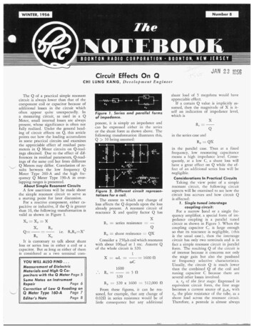
dAN 23 1358Circuit Effects On QCHI LUNG K A N G , D e u e l o p m e n t E n g i n e e rIIFigure 7 . berres and parallel tormsof impedance.ponent, it is simply an impedance andcan be expressed either in the seriesor the shunt form as shown above. Thefollowing transformation illustrates this,Q 10 being assumed:7:- f- -R R2 T Figure 2. Different circuit representations for a coil.The extent to which any change ofloss affects the Q depends upon the lossalready present. A resonant circuit ofreactance X and quality factor Q hasXzseries resistance -QR, shunt resistance Q XConsider a 250ph coil which resonateswith about 1OOppf at 1 mc. Assume Qof the whole circuit is 320.1Correction of Low Q Reading onb l6OORX oLz---.YOU WILL ALSO F I N D . .Measurement of DielectricMaterials and High Q Capacitors with the Q Meter Page 5Some Notes on InstrumentRepairPage 6Q Meter Type 160-APage 7Editor's NotePage 8in the series case andR,, QXConsiderations In Practical CircuitsIL- sR R,Qin the parallel case. Thus at a fixedfrequency, low resonating capacitancemeans a high impedance level. Consequently, at a low C, a shunt loss willhave a great effect on Q while the effect of an additional series loss will benegligible.W'I!RZshunt load of 5 megohms would haveappreciable effect.If a certain Q value is implicitly assumed, then the magnitude of X is itself an indication of impedance level,which isXR,-WC1600. RS - 5R320R, 320 x 1600 512,000 2!From these figures, it can be reasoned, for example, that any change of0.020 in series resistance would be oflittle consequence but any additionalTaking the view point of a simpleresonant circuit, the following circuitaspects will be examined to see how thecircuit loss accrues and how circuit Qis affected:I . Single tuned interstagecoupling circuit:For a narrow band or a single frequency amplifier, a special form of impedance coupling is a parallel tunedcircuit as shown in Figure 3. When thecoupling capacitor C,. is large enoughso that its reactance is negligible, (thisis the usual case), then the interstagecircuit has only two terminals and is infact a simple resonant circuit in parallelform. The resulting Q of the circuit isof interest because it concerns not onlythe stage gain but also the passbandor frequency selective characteristics.Usually, the circuit Q is much lowerthan the combined Q of the coil andtuning capacitor C because there areseveral other losses involved.a. vP of t h e first stage: Expressed inequivalent circuit form, the first stagebecomes a current source of gllleF:withr,,, the plate resistance of the tube, as ashunt load across the resonant circuit.Therefore, a pentode is almost always
- .BOONTONT H E BRC NOTEBOOK is publishedfour times a year by the Boonton RadioCorporation. I t is mailed free of chargeto scientists, engineers and other interested persons in the communicationsand electronics fields. T h e contents maybe reprinted only with written permission f r o m the editor. Your commentsand suggestions are welcome, andshould be addressed to: Editor, T H EB R C N O T E B O O K , B o o n t o n RadioCorporation, Boonton, N . 1.CCimpedance of the generator does notunduly affect the Q of the circuit. Theoutput impedance of a signal generator is generally 50 ohms, which ismuch too low to be connected directlyacross the resonant circuit. (Also toohigh to be used for series feeding theresonant circuit). The usual practice isto increase the output impedance byinserting a high series resistor, R, inseries with the signal generator. Thisresistor, R, should be high relative to thetuned impedance (R,, QwL) , becauseR 50 is indeed loading the circuit.Any detector connected across the resonant circuit, of course, is an additionalload.Similar considerations hold when thecathode output of a tube is used to feeda resonant circuit.3. Physical aspects ofcomponents in a circuit:Figure 3. Single tuned interstagecoupling circuit.used as the first tube since its higherr,, means less loading.b. I n p u t loading of the f o l l o w i n gstage: Vacuum tube input impedance isgenerally considered high, but relativeto the impedance of a parallel resonantcircuit, the contrary is more often thecase especially at higher frequencies.c. Stray capacitances with associatedlosses: This could be important if thestray capacitance is an appreciable partof the total resonating capacitance. Tokeep Q high, the metal parts with whichthe stray capacitance is associated shouldbe well grounded and dielectrics involved should have low loss.d. G r i d resistor R, loading o n theresonant circuit:e. Loss d u e t o B f f e e d i n g circuit:As shown in Figure 3, the decouplingcapacitor C1 may introduce some seriesloss into the coil. And if parallel feedthrough a choke is used, a shunt loadis added.If R,, is the final equivalent shuntlosses of the whole circuit, includinglosses of coil and capacitor, thenQ -R,WLand the input voltage to the next stagewill be glllegRL,.2. Feeding a parallel resonantcircuitbya signal generator:When a signal generator like BRCSweep Signal Generator Type 240-A isused to feed a parallel resonant circuit,care must be taken so that the oiitputWhat is under consideration here isthe change that is involved when acomponent is physically connected intoa circuit. When, for example, a coil isshunted across a capacitor, in an idealized circuit analysis, this means nothing more than putting two symbols together. But actually, changes are involved in two general aspects: ( 1 ) dueto proximity of two components, changeof both inductance and capacitance ispossible; ( 2 ) the physical connectinglink, perhaps a copper strap, may havean effect on circuit performance whichcannot be ignored. This kind of criticalconsideration primarily arises in problems of measurement, but in practicalcircuits stray capacitance and lead inductance mean practically the samething. This situation becomes more important as the use of lumped constantcircuit elements is extended to higherfrequencies where coils become smalland series impedances very low. AO.lph coil at 50 mc has a reactance ofabout 3212. A Q of 320 means a seriesresistance of 32/320 I0.10. If at sucha low impedance level, the contact resistance of a plug-in connection is of theorder of a milliohm, it will show an appreciable effect on the Q of the coil.When this same coil is measured on aQ Meter, a poor connection will leadto a jitter in the Q reading or widevariations of results.4. Circuit Q and Effective Q:Why does a coil of Q 300 measureonly 250, for example, on the Q Meter?Why do different types of Q Meterssometimes give different readings forthe same coil! These are the questionsto be clarified here.The coil:Consider a coil expressed in a series2RADIOCORPORATIONform with inductance L and resistanceR,; Le., a two-terminal element of impedance 2 R, jwL. It has a qualityfactor ofLWLd -.RsThe Q and 2 are primarily characteristics of the coil alone. But when thecoil is connected into a circuit, theproximity effect can change the distributed capacitance and create mutualinductance. Hence, it should be realizedthat strictly speaking an impedance,hence its Q, is not completely defineduntil the way it is connected into a circuit is specified.The measuring circuit:The Q Meter measuring circuit consists of a signal source, a variable tuning capacitor, and a voltmeter. Ideallywith the coil connected, the circuitshould be as shown in Figure 4a, butactually the circuit for the Q MeterType 260-A should be represented asin Figure 4b. (For Q Meter Type190-A, see its Manual). These spuriouselements that are unavoidably introduced are known as residuals - residual inductance and residual shunt orseries losses-Figure 4. Q . iter circuit.Rql is due to the oscillator injectioncircuit.R,? includes series resistance of binding posts, connecting straps, etc.L,, is the residual inductance of binding posts and connecting straps.R,, includes the voltmeter input resistance, the 100 megohm grid resistorand other dielectric losses across thecapacitor.The Q Meter is designed to read theQ of the whole circuit. The reactanceL, instead of L, and inis now Loternal losses are added. The resulting Q is of course not the same as the Qof the coil. Recognizing the effect ofthe internal losses, two kinds of Q are-
THENOTEBOOK1defined: ( a ) Circuit Q; Q of the wholeQ measuring circuit including losses ofthe coil, all the internal residual lossesthe effect of the residual inductance.u and( b ) Effective Q: Q of the coil itself asmounted on the Q Meter used (proximity effect included). In many but notin all cases, circuit Q is essentially equalto effective Q.The term indicated Q is often used;this refers to the circuit Q as indicatedby the Q Meter which is designed toindicate circuit Q. This means that thedifference between indicated and Lircuit Q is strictly a matter of the accuracy of the Q Meter. If accuracy ofthe Q Meter is not in question, iizdicated and circuit Q mean the samething.-Now, circuit Q depends on coil lossas well as internal losses. Therefore, asinternal losses may differ among different Q Meters, either of the same typeor of different types, the circuit Qmeasured on different Q Meters willdiffer from each other even if the coilmeasured is the same one. This difference is usually small, especially if the QMeters used are of the same type. Butin the overlapping ranges (20-50 mc)of the 260-A and 190-A Q Meters, it canbe as much as 5 0 p in some unusualcases. This may seem startling but as explained in the next section, this difference can be completely accounted forby the difference in residuals, which aremuch lower in the 190-A Q Metersince it is designed to cover a higherfrequency range.Correlation of 190-A and 260-A QMeters in OverlappingFrequency RangesWhen the residual parameters in a QMeter are all known, correction can bemade on the circuit Q to allow for theeffects of the residuals and thus obtainthe effective Q by computation. Theeffective Q readings for the same coilas computed from the circuit Q in different Q Meters should be the same,except for a possible difference due tothe difference in proximity effects andcontact resistance. When proper care istaken, this difference should be verysmall.In the overlapping ranges (20-50mc) both Type 190-A and 260-A QMeters can be represented by the circuit shown in Figure Sa, which can betransformed into Figure 5b and 5c. ( Amore refined circuit for the 190-A QMeter is given in its Manual).Cc, -1-O'L,,CWSL,C-L,,1--L,, L,L,, b.C.Figure 5. Q Meter equivalent circuits.whereL,, R, inductance and resistanceof coilL,, total internal residual inductanceR, total internal series resistance0.0026 p h in 190-A Q-MeterAt 50 mc, 100 ppf is in resonancewith O.1ph. Evidently, L,, in 260-A QMeter becomes appreciable then.B. Correction for residual losses.Qi circuit Q indicated Q(Perfect Q Meter accuracy assumed )Q'. effective QWCQi1G,, 10.015 p h in 260-A Q-MeterG,, R,w'C' total internal shuntR,lconductance. G,, G,,R , w V total internal loss expressed as shunt conductance.The correlation of the two Q readingsof the same coil in Type 260-A and190-A Q Meters will be demonstratedby comparing the results of effective Qcomputed in each case from the indicated Q readings. The indicated Q willbe taken the same as circuit Q; Le., eachQ Meter is assumed to have perfect accuracy. To get effective Q, the correction has two parts; ( A ) for residual inductance, ( B ) for residual losses.A. Correction for residual inductance:Here the reactance of the coil itself willbe computed.L, L - L,,OL, WL - WL,,1since OL -at resonanceOC1OL, -- W L , ,WC1- - ( 1 - W'L,,CjqOC -- w'(L,, L,)C-L,, L,L"OC1LO-(l----I1WCL,, Lsince w' ( Lc, Lxj C w'LC 1The equivalent capacitance that willresonate with L, is3l-W'L,,C1Qc.- RxwCxR,wCQi, G,,, O, C and L,, are knownquantities. QI,can be computed by eliminating R, between equations foi Qi andQ(,above. So the computation for Q,. isstraightforward in principle and doesnot require discussion. The method outlined is only to minimize the work ofcomputation and also give an indication as to the relative weight of different parameters and their interrelation.Steps to compute Qc. will be givenbelow with a derivation outlined later.Due to difference in expressions forshunt loss, the 260-A and 190-A QMeters have to be treated separately:I . FOT t h e 260-A Q Meter:Ca,)Compute C, from C, 1--O'L,,Cb. j Find a from a vs C' graph( Figure 6 )c. ) Correct a to get a' 1 250a - (- I), if this appears3Qisignificant.d.) Compute y by y
BOONTONwhere atogether with the a vs C' graph.The a to a' correction refers to leveleffect not discussed so far. In the260-A Q Meter, a t a frequency above20 mc, the voltmeter loading increasesas the signal level (i.e., the Q reading)decreases. The given correction for a isgood for Qi 100.2. For the 190-A Q Meter.equivalent shunt loss dueto residual series resistanceactual internal shunt lossy Total internal loss as a fraction oftotal circuit lossSo a shows the relative importanceof shunt and series residual losses.And if y 0.10, it means 10% ofthe total circuit loss is not due to thecoil measured but due to the internalloss of the Q Meter. The effective Qshould therefore be higher than the circuit Q by the factor11I 1.111-y1-0.1TheCc1-factor in Q(. -eQicc,QiG,,-WCR,w2C2R,O'C?( I 1GI)G,, kf'GI;Qi.y -fkQifiiica 0.00114 -a277-ccwf1l--W'L,,Cb.) Find P from P vs C' graph(Figure 7 )c.) Compute 7 by 7 CORPORATION 1,a ------a.) Compute C, from C, z-c,RADIO-QeRswCsGt G,, R x ' C P 0.00573 QiPCPPfEliminate R, between Qe and G,.1d.) Obtain Qc.by Qc - -Qics1-7where the physical meaning of P and 7correspond respectively to those of aand y .Outline of derivation of above relations (for 260-A Q Meter) :G,Gp Rsw2C2y GtOC1-ytakes care of the effect due to residualinductance. When frequency and capacitance are changed, the resulting effect on y, i.e., on the difference betweeneffective Q and circuit Q can be easilyestimated from the expressionQifiiic-Y 0.00114 a'Qi100.5 ppf301CQi0.015 p hL"dL,Ccs--C4C101005.700.113-1 )QI - (-2503-1)4.263Q1IQ2Qi10.00573 00.omma0PI 0.0979CPPf10000Figure 7 . /3 versus C' graph for QMeter Type 790-A.103.14.15graphCorrection for a1250-cs83801IO1.0261--W'L,CC2a' a191CY106310--cs- ( -1 01.161-O?L,,Ca from a vs C'A-1-0.0026 p h0.0258LOW'L"C0.135320c1Qe -- - e cs1-7Qi326
THENOTEBOOK Measurement of Dielectric Materialsand Hi Q Capacitors with the Q MeteriiN O R M A N L. RIEMENSCHNEIDER, S a l e s E l z g i n e e vDissipation Factor ofInsulating MaterialA considerable amount of materialhas been published on this subject bymany experts in this field describingthe various techniques and the precautions to be observed in making measurenxnts. From our own field work withcompanies involved in these measurements, we have come to realize the needof methods for use where the expediency required for process control workcan be obtained at some possible sacrifice in accuracy by eliminating speciallydeveloped specimen holders, guardrings, etc. It is in this sense that weoffer the following suggestions for making measurements of this nature.To review the overall operation verybriefly, let it suffice to say the sampleto be measured will be converted intoa capacitor by adding suitable electrodes to the two parallel surfaces, andmeasurements made of its equivalentparallel capacity (C,, ) and resistance(R,,) . From thcse two parameters, theDissipation factor11-DT-QwC&can be determined. The whole operation can be resolved into a sequence oflogical steps, with the necessary precautions, described below:Operating Procedurei/The ground plate and clip shown inFig. 2 have been used with very satisfactory results. Prepare a plate and clipas shown and install on the Q Meter(see Figure 1) .Select the desired frequency and allow the Q Meter to warm up. Use ashielded coil whose inductance is suchthat it will resonate at the desired frequency with the Q Capacitor set at approximately 50 p p f . It is desirable touse the least possible amount of capacitance to resonate the coil since any dielertric specimen loss added to the circuit later will be more conspicuouswhen paralleled across a low capacity(high impedance) than a high capacity(low impedance). In any case, the lowest capacity that can be used will equalthe sum of the sample capacity plus theminimum capacity ( 30 ppf ) of the QMeter internal resonating capacitor.Selection and Preparationof SamplesInasmuch as the ratio of loss and ca-“’Ifigure 1. The author measuring the dissipation factor of Teflon.pacitance vary uniformly, there is quitea latitude in the choice of sample size.Very often either a 2” diameter, Y8’’thick, round disc, or a 4” x 4” squaresample is chosen. It is of some advantage to use a configuration whose areacan be readily computed if the dielectricconstant is to be measured. In any case,increasing the area or decreasing thethickness will tend to increase themeasurable “lossiness”which is desirablewhen measuring materials having verylow dissipation factors. The sampleshould be clean and handling of theedges should be avoided to preclude thepossibility of any contamination. Applya very thin layer of Petrolatum and addaluminum or soft lead foils cut tosample size to both sides of the sample.Be sure to “roll out” any air pockets sothat intimate contact is made at allpoints. It is also possible to employcommercially available conductive coatings which can be painted or “vacuumevaporated” on the sample.adjusted for resonance, a much closerreading can be made of capacitance.Make a record of Q z and Ca at thispoint. (These readings are designatedas Qa and Cz since in Q Meter measurements they are usually recorded as thesecond reading). The procedure hasbeen reversed here since specimens canbe removed faster than they can bemounted and it is desirable to minimizethe elapsed rime between readings.Those using a 190-A or 260-A Meterwill want to take advantage of the“Delta Q ’ scale on the instrument. Inasmuch as the Q1 reading will be higherthan the Q2 reading just made, the“Delta Q ’ adjustment will not be referenced to zero but to some other convenient point on the scale. It is alsovery advantageous to hold the “DeltaQ ’ key in its operated position longenough to take advantage of the increased meter sensitivity and refine thecircuit tuning as needed. The referencepoint finally chosen should be recorded.Measurements withSample ConnectedMeasurements withSample RemovedWith the ground plate secured to thecase of the Q Meter and connected to“Lo” Capacitor post, mount the specimen on the plate and hold in positionwith the spring clip connected to the“Hi” Capacitor post. After havingadjusted the “Q Zero adjust” knob, increase the oscillator output control untilthe “Multiply-Q-By” Meter indjcates“1”. Be sure this needle is at this pointduring all measurements. Rotate the QCapacitor to obtain resonance as indicated by a maximum deflection on the“Circuit Q ’ meter. If the main condenser is set at the nearest calibrationon the dial and the vernier condenserRemove sample and Spring Clip Connector and resonate the circuit as above.Operate “Delta Q ’ key when at pesonance and refine tuning with vernier.Read “Delta Q” value first and then thevalue of C1. Q1 will be equal to Qlplas the change (neglecting sign) in“Delta Q” reading. The needle, when in“Delta Q ’ operation, should alwaysmove to the right when going from theQ2 reading (with sample) to the Q1reading (without sample). For thoseusing older type Q Meters that do not5have the Delta Q scale, it will be necessary to read Q1 from the meter andcompute the change.
BOONTONCalculation of Dissipation FactorThe dissipation, D, is found to be:CI(Qi -Q.1D (1)(Ci - C,)QIvernier condenser; total 93.6QI Q2“Delta Q” 2323.8 235.8 Computations:Ci (QiQt! And of course Q1 Q:!“Delta Q ’when the “Delta Q” scale is used.Examination of the above formulaemphasizes the importance of determining the (Q1 - Q 2 ) or “Delta Q” termas accurately as possible, since the measurement accuracy is in the same orderas the determination accuracy of thisterm.Example of TechniqueAs a means of illustrating the technique, the following measurements werewere made at 1 mc on a piece of Teflon,2” in diameter and 0.077” thick.HOLE SCHEDULEA-.201 D I A - 1 HOLERHODIUM P L A T E D -(CI - Cz)Q.1QIQ.C1 (DeltaQ)-(CI - G ) QiQ.93.6 X 3.8-x 235.8 X3 56 x 10’1.12 x 10”20.48-232 ‘.000318 dissipation factor.It might be worth noting that as theinsulating properties of the materialstested become better, the quantity(Q1 - Q.), called “Delta Q”, becomessmaller to the extent that the use of the“Delta Q ’ scale, incorporated in boththe 190-A and 260-A Q Meters, becomes mandatory.Dielectric ConstantThe dielectric constant, K, can befound from4.45 c, tK (2)SWhere:C, Sample capacity C1 -Cz(from above)t average thickness of material ininchesS area of active dielectric materialbetween electrodes in square inchesUsing the values determined above,the dielectric constant of the sample is:GROUND P L A T E4.45x2048x,077K 7TMATFINSILVER ARHODIUM PLATESAMPLE RETAINING C L I PFigure 2 . Details of dielectric testfixtures for Type 760-A and 2 6 0 - AQ Meters.With Sample Attached:Cz 73.0 main condenser, and 0.12for vernier condenser; total 73.12ppfQz232“Delta Q ’ set at 25Remove Sample:“Delta Q” reading 2 1.2AQ 25 - 21.2 3.8C1 93 main condenser and 0.6 for 2.28 for the sample testedIf S and t are measured in centimeters11.3 C, tK (3)SUse of the Hartshorne HolderSpecimens of suitable size and thickness can be mounted in a Hartshornetype holder and measured in three ways:1. “Resonant Circuit, Resonance RiseMethod”: This is similar to the technique shown above but refined to theextent of mounting the specimen in aHartshorne Specimen Holder.2. “Variable Susceptance Methodwith Air Gap”: Here the specimen ismounted in a Hartshorne Holder and6RADIOCORPORATIONan Air Gap of 0.005” to 0.050” is introduced above the surface of tke specimen. .This method has been found suitable for measurements from 10 kc upto 100 mc.3. “Variable Susceptance Methodwithout Air Gap”: This method, similarto the above except that the specimenis clamped in the holder instead of allowing an air gap, is employed for materials whose losses are too small to bemeasured by the air gap technique.Boonton Radio Corporation DrawingNumber C-302252 gives the specifications for the adapter plate used tomount the Ceneral Radio Type 1690-AHartshorne Holder to any BRC QMeter and is available upon request.Measurements can also be made ofinsulating liquids with the provision ofa suitable cell or container.S O M E N O T E S ONI N S T R U M E N T REPAIROne of the responsibilities of a manufacturer of precision electronic instruments is to provide facilities for repairing and maintaining his products. In asense this responsibility begins in thedevelopment and design stages of aninstrument’s history for it is in thisstage that proper design will minimizethe need for later repair. Also at thisstage arrangements which facilitate later drepair can be made.Boonton Radio Corporation operatesa factory repair facility and also hasauthorized repair of its instruments bycompetent groups operated by its Representatives throughout this country andCanada. When your instrument requiresrepair, contact the office nearest to you,included in the list on the back page ofthis issue.When your instrument is to be returned to the factory for service the following steps will expedite the repair.1. State as completely as possible bothon an instrument tag as well as onyour order the nature of the problem which you have experienced.Too much information is far betterInspector aligning the RF section ofSignal Generator Type 27 7-A totrack with the frequency dial.,,
THE-NOTEBOOKthan too little. If the problem isintermittent in nature be very specific. W e sometimes have instrumentswith this type of trouble which reiifuse to misbehave for us.2. State on your order whether we mayproceed and bill you in accordancewith our standard pricing system orwhether you require that we secureyour approval of the price beforeproceeding. The price will be thesame in both cases but delay in delivery will be minimized by yourpermission to proceed in accordancewith our standard system. Your acknowledgement copy of the orderwill always show the price.Return the complete instrument eventhough you may think that someportion is not at fault. Some of ourSignal Generators consist of twounits (the power supply and signalgenerator) ; send both.If you have made a change in yourinstrument and want the instrumentback in the same form tell us so. OurInspection Department will alwayswant to make your instrument standard.Some of our instruments have beenin production for several years and wehave built up a reasonable amount ofrepair history. For these instruments wehave established standard prices basedon our average experience. These pricesare based on the age and condition ofthe instrument. Thus all instruments ina given age bracket in average condition for that age will be priced at oneof our standard prices. These prices arestudied and modified at the end of eachyear. This system saves you money andtime since it avoids the necessity of acost analysis on each individual repair.A good repair facility requires goodcommunication between customer andfactory. If you have justified abnormalrequirements for quick return of yourinstrument let us know. W e will do ourvery best to accommodate you. Ask onlyif you have a real need. If everybodyasks we cannot improve our speed foranybody.Correction of l o w Q ReadingOn Q Meter Type 160-ASAMUEL WALTERS, E d i t o r ,eL,Occasionally the mica plate whichsupports the measuring terminals ontop of the Q Meter Type 160-A mustbe replaced because of surface contamination or cracking of the surface whichbreaks the moisture-proofing compound.The resultant rf leakage from the H Ipost measuring terminal to ground effectively adds a shunt resistance acrossthe circuit under test causing a lowIndicated Q reading. SometiTes therupture or contamination is not visuallyapparent although just as electrically defective as the obvious case. However,the mica terminal insulator should notas a matter of course be changed whenabnormally low Indicated Q readingsare observed since there are three otherconditions that will cause shunt lossesand excessive loading of the circuit under test. These other conditions are:1. Cracked mica internal resonatingcapacitor stator insulators ( i n laterQ Meters pyrex glass was usedwhich rarely causes trouble).2. D e f e c t i v e Q v o l t m e t e r t u b e(105-A).3. Grid leak associated with 105-A(100 megohm resistor) in deteriorated condition.Before proceeding to isolate the condition causing the shunt loss, one mustfirst determine whether the low Q read-The Notebookings are due to shunt losses or someother cause. This can quickly be determined with the use of the Q StandardType 513-A”, a shielded reference inductor designed to maintain accuratelycalibrated and highly stable inductanceand Q characteristics. Assuming shuntlosses are indicated, we proceed to thenext step: the isolation of the conditioncausing the shunt loss.F R E Q 7IFFINCERSTHIFREQILO (THEFigure 1 . Bottom View: Binding postQ Meter Typeplate assembly160-A.Determination of Shunt Loss-The procedure is as follows:a ) Position the Q Meter to be tested( Q Meter A ) three inches ro the rearof another Type 1 6 0 - Q Meter ( QMeter B used as an indicating unit).Both Q Meters are to face the operator.b ) Connect a Type 103-A22 Inductorto the COIL terminals of Q Meter B.Interconnect the G N D terminals of the7two Q Meters by means of a 15 inchlength of No. 18 stranded copper wire.Suspend a 17 inch length of No. 20 orNo. 18 bare tinned copper wire (singlestrand) from the HI-COND terminalpost of Q Meter B so that the free endof this lead points directly down toward,and is one inch removed from, the HICOND terminal post of Q Meter A.This lead should be positioned as far aspossible from other objects.c ) Apply ac power to W- hfa ers.13Figure 2. Angle of alignment ofwiper fingers.d ) Adjust Q Meter A for oscillatorfrequency of approximately 800 kc anda Multi-Q-By reading of approximately1.2. Adjust vtvm zero in usual mannerand adjust capacitance dial to 30,upf.e ) Adjust Q Meter B to read the Qof the Type 103-A22 Inductor at tuning capacitance dial reading of 7 0 p p fand an oscillator frequency of approximately 1.13 mc so that the IndicatedQ reading should fall between 221-235.Note the exact value of this readingas Q15.f ) Now interconnect the COND-HIterminal posts of the two Q Meters byinserting the tip of the suspended barelead into the corresponding terminalhole of Q Meter A. Resonate Q MeterB by adjusting its capacitance dial.Note the new Q reading on Q MeterB as Qa.g ) If Q1 - Q2 14 or less thecause of faulty Q Meter “A” Q readingprobably lies elsewhere than in the internal Q measuring circuit.h ) If Q1 - Q2 exceeds 14 proceedas follows to more specifically locatethe cause of excessive errors in Q reading. Turn ac power off Q Meter A.Disconnect grid connector clip from105-A tube grid cap in Q Meter A,allowing grid lead from Q-unit to hangin space. With the two Q Meters interconnected as for reading Q2 (see ( f )above), but with the ac power stillturned off Q Meter A, resonate Q MeterB by adjusting its capacitance dial.Note Q Meter B Q reading as Q: .i ) If QR - Q2 exceeds 8, voltmetertube 105-A should be replaced as defective.j ) If Q1 - Q:( exceeds 6, excessive
-. -BOONTONRADIOMica Terminal InsulatorThe replacement of the mica terminalinsulator is a relatively simple procedure. However, this procedure must befollowed to avoid damage to the thermocouple and expedite the mica plate’sremoval and replacement.1. Unscrew knurled knobs
R, shunt resistance QX Q Consider a 250ph coil which resonates with about 1OOppf at 1 mc. Assume Q of the whole circuit is 320. 1 WC X oLz--- l6OOR 1600 320 . RS - 5R R, 320 x 1600 512,000 !2 From these figures, it can be rea- soned, for example, that any change of 0.020 in series resistance would be of
