Transcription
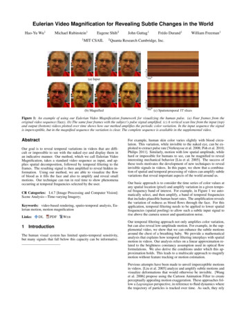
Eulerian Video Magnification for Revealing Subtle Changes in the WorldHao-Yu Wu1Michael Rubinstein11Eugene Shih2MIT CSAIL2John Guttag1Frédo Durand1William Freeman1Quanta Research Cambridge, Inc.ytime(a) Inputy(b) Magnifiedtime(c) Spatiotemporal YT slicesFigure 1: An example of using our Eulerian Video Magnification framework for visualizing the human pulse. (a) Four frames from theoriginal video sequence (face). (b) The same four frames with the subject’s pulse signal amplified. (c) A vertical scan line from the input (top)and output (bottom) videos plotted over time shows how our method amplifies the periodic color variation. In the input sequence the signalis imperceptible, but in the magnified sequence the variation is clear. The complete sequence is available in the supplemental video.AbstractOur goal is to reveal temporal variations in videos that are difficult or impossible to see with the naked eye and display them inan indicative manner. Our method, which we call Eulerian VideoMagnification, takes a standard video sequence as input, and applies spatial decomposition, followed by temporal filtering to theframes. The resulting signal is then amplified to reveal hidden information. Using our method, we are able to visualize the flowof blood as it fills the face and also to amplify and reveal smallmotions. Our technique can run in real time to show phenomenaoccurring at temporal frequencies selected by the user.CR Categories: I.4.7 [Image Processing and Computer Vision]:Scene Analysis—Time-varying Imagery;Keywords: video-based rendering, spatio-temporal analysis, Eulerian motion, motion magnificationLinks:1DLPDFW EBIntroductionThe human visual system has limited spatio-temporal sensitivity,but many signals that fall below this capacity can be informative.For example, human skin color varies slightly with blood circulation. This variation, while invisible to the naked eye, can be exploited to extract pulse rate [Verkruysse et al. 2008; Poh et al. 2010;Philips 2011]. Similarly, motion with low spatial amplitude, whilehard or impossible for humans to see, can be magnified to revealinteresting mechanical behavior [Liu et al. 2005]. The success ofthese tools motivates the development of new techniques to revealinvisible signals in videos. In this paper, we show that a combination of spatial and temporal processing of videos can amplify subtlevariations that reveal important aspects of the world around us.Our basic approach is to consider the time series of color values atany spatial location (pixel) and amplify variation in a given temporal frequency band of interest. For example, in Figure 1 we automatically select, and then amplify, a band of temporal frequenciesthat includes plausible human heart rates. The amplification revealsthe variation of redness as blood flows through the face. For thisapplication, temporal filtering needs to be applied to lower spatialfrequencies (spatial pooling) to allow such a subtle input signal torise above the camera sensor and quantization noise.Our temporal filtering approach not only amplifies color variation,but can also reveal low-amplitude motion. For example, in the supplemental video, we show that we can enhance the subtle motionsaround the chest of a breathing baby. We provide a mathematicalanalysis that explains how temporal filtering interplays with spatialmotion in videos. Our analysis relies on a linear approximation related to the brightness constancy assumption used in optical flowformulations. We also derive the conditions under which this approximation holds. This leads to a multiscale approach to magnifymotion without feature tracking or motion estimation.Previous attempts have been made to unveil imperceptible motionsin videos. [Liu et al. 2005] analyze and amplify subtle motions andvisualize deformations that would otherwise be invisible. [Wanget al. 2006] propose using the Cartoon Animation Filter to createperceptually appealing motion exaggeration. These approaches follow a Lagrangian perspective, in reference to fluid dynamics wherethe trajectory of particles is tracked over time. As such, they rely
nΣ ytimeInput videoα1ReconstructionTemporalProcessingyEulerian video magnificationtimeOutput videoFigure 2: Overview of the Eulerian video magnification framework. The system first decomposes the input video sequence into differentspatial frequency bands, and applies the same temporal filter to all bands. The filtered spatial bands are then amplified by a given factor α,added back to the original signal, and collapsed to generate the output video. The choice of temporal filter and amplification factors can betuned to support different applications. For example, we use the system to reveal unseen motions of a Digital SLR camera, caused by theflipping mirror during a photo burst (camera; full sequences are available in the supplemental video).on accurate motion estimation, which is computationally expensiveand difficult to make artifact-free, especially at regions of occlusionboundaries and complicated motions. Moreover, Liu et al. [2005]have shown that additional techniques, including motion segmentation and image in-painting, are required to produce good qualitysynthesis. This increases the complexity of the algorithm further.In contrast, we are inspired by the Eulerian perspective, whereproperties of a voxel of fluid, such as pressure and velocity, evolveover time. In our case, we study and amplify the variation of pixelvalues over time, in a spatially-multiscale manner. In our Eulerianapproach to motion magnification, we do not explicitly estimatemotion, but rather exaggerate motion by amplifying temporal colorchanges at fixed positions. We rely on the same differential approximations that form the basis of optical flow algorithms [Lucas andKanade 1981; Horn and Schunck 1981].Temporal processing has been used previously to extract invisiblesignals [Poh et al. 2010] and to smooth motions [Fuchs et al. 2010].For example, Poh et al. [2010] extract a heart rate from a video of aface based on the temporal variation of the skin color, which is normally invisible to the human eye. They focus on extracting a singlenumber, whereas we use localized spatial pooling and bandpass filtering to extract and reveal visually the signal corresponding to thepulse. This primal domain analysis allows us to amplify and visualize the pulse signal at each location on the face. This has important potential monitoring and diagnostic applications to medicine,where, for example, the asymmetry in facial blood flow can be asymptom of arterial problems.Fuchs et al. [2010] use per-pixel temporal filters to dampen temporal aliasing of motion in videos. They also discuss the high-passfiltering of motion, but mostly for non-photorealistic effects and forlarge motions (Figure 11 in their paper). In contrast, our methodstrives to make imperceptible motions visible using a multiscaleapproach. We analyze our method theoretically and show that itapplies only for small motions.In this paper, we make several contributions. First, we demonstrate that nearly invisible changes in a dynamic environment can berevealed through Eulerian spatio-temporal processing of standardmonocular video sequences. Moreover, for a range of amplificationvalues that is suitable for various applications, explicit motion estimation is not required to amplify motion in natural videos. Ourapproach is robust and runs in real time. Second, we provide ananalysis of the link between temporal filtering and spatial motionand show that our method is best suited to small displacements andlower spatial frequencies. Third, we present a single frameworkthat can be used to amplify both spatial motion and purely temporalchanges, e.g., the heart pulse, and can be adjusted to amplify particular temporal frequencies—a feature which is not supported byLagrangian methods. Finally, we analytically and empirically compare Eulerian and Lagrangian motion magnification approaches under different noisy conditions. To demonstrate our approach, wepresent several examples where our method makes subtle variationsin a scene visible.2Space-time video processingOur approach combines spatial and temporal processing to emphasize subtle temporal changes in a video. The process is illustrated inFigure 2. We first decompose the video sequence into different spatial frequency bands. These bands might be magnified differentlybecause (a) they might exhibit different signal-to-noise ratios or (b)they might contain spatial frequencies for which the linear approximation used in our motion magnification does not hold (Sect. 3).In the latter case, we reduce the amplification for these bands tosuppress artifacts. When the goal of spatial processing is simply toincrease temporal signal-to-noise ratio by pooling multiple pixels,we spatially low-pass filter the frames of the video and downsamplethem for computational efficiency. In the general case, however, wecompute a full Laplacian pyramid [Burt and Adelson 1983].We then perform temporal processing on each spatial band. Weconsider the time series corresponding to the value of a pixel in afrequency band and apply a bandpass filter to extract the frequencybands of interest. For example, we might select frequencies within0.4-4Hz, corresponding to 24-240 beats per minute, if we wish tomagnify a pulse. If we are able to extract the pulse rate, we can usea narrow band around that value. The temporal processing is uniform for all spatial levels, and for all pixels within each level. Wethen multiply the extracted bandpassed signal by a magnificationfactor α. This factor can be specified by the user, and may be attenuated automatically according to guidelines in Sect. 3.2. Possibletemporal filters are discussed in Sect. 4. Next, we add the magnified signal to the original and collapse the spatial pyramid to obtain
the final output. Since natural videos are spatially and temporallysmooth, and since our filtering is performed uniformly over the pixels, our method implicitly maintains spatiotemporal coherency ofthe results.Eulerian motion magnificationOur processing can amplify small motion even though we do nottrack motion as in Lagrangian methods [Liu et al. 2005; Wang et al.2006]. In this section, we show how temporal processing producesmotion magnification using an analysis that relies on the first-orderTaylor series expansions common in optical flow analyses [Lucasand Kanade 1981; Horn and Schunck 1981].3.1B(x, t)Intensity3αB(x, t)First-order motionTo explain the relationship between temporal processing and motion magnification, we consider the simple case of a 1D signal undergoing translational motion. This analysis generalizes directly tolocally-translational motion in 2D.Let I(x, t) denote the image intensity at position x and time t.Since the image undergoes translational motion, we can express theobserved intensities with respect to a displacement function δ(t),such that I(x, t) f (x δ(t)) and I(x, 0) f (x). The goal ofmotion magnification is to synthesize the signalˆ t) f (x (1 α)δ(t))I(x,(1)for some amplification factor α.Assuming the image can be approximated by a first-order Taylorseries expansion, we write the image at time t, f (x δ(t)) in afirst-order Taylor expansion about x, asI(x, t) f (x) δ(t) f (x). x f (x). x(2)(3)In our process, we then amplify that bandpass signal by α and addit back to I(x, t), resulting in the processed signal t) I(x, t) αB(x, t).I(x,(4)Combining Eqs. 2, 3, and 4, we have t) f (x) (1 α)δ(t) f (x) .I(x, x(5)Assuming the first-order Taylor expansion holds for the amplifiedlarger perturbation, (1 α)δ(t), we can relate the amplificationof the temporally bandpassed signal to motion magnification. Theprocessed output is simply t) f (x (1 α)δ(t)).I(x, 30f (x)δαδx (space)5040f (x δ)f (x) δ f x(x)(6)This shows that the processing magnifies motions—the spatial displacement δ(t) of the local image f (x) at time t, has been amplifiedto a magnitude of (1 α).This process is illustrated for a single sinusoid in Figure 3. Fora low frequency cosine wave and a relatively small displacement,60B(x, t)7080f (x) (1 α)B(x, t)Figure 3: Temporal filtering can approximate spatial translation.This effect is demonstrated here on a 1D signal, but equally appliesto 2D. The input signal is shown at two time instants: I(x, t) f (x) at time t and I(x, t 1) f (x δ) at time t 1. The firstorder Taylor series expansion of I(x, t 1) about x approximateswell the translated signal. The temporal bandpass is amplified andadded to the original signal to generate a larger translation. In thisexample α 1, magnifying the motion by 100%, and the temporalfilter is a finite difference filter, subtracting the two curves.δ(t), the first-order Taylor series expansion serves as a good approximation for the translated signal at time t 1. When boostingthe temporal signal by α and adding it back to I(x, t), we approximate that wave translated by (1 α)δ.For completeness, let us return to the more general case where δ(t)is not entirely within the passband of the temporal filter. In this case,let δk (t), indexed by k, represent the different temporal spectralcomponents of δ(t). Each δk (t) will be attenuated by the temporalfiltering by a factor γk . This results in a bandpassed signal,B(x, t) Xγk δk (t)kLet B(x, t) be the result of applying a broadband temporal bandpass filter to I(x, t) at every position x (picking out everything except f (x) in Eq. 2). For now, let us assume the motion signal, δ(t),is within the passband of the temporal bandpass filter (we will relaxthat assumption later). Then we haveB(x, t) δ(t)200 f (x) x(7)(compare with Eq. 3). Because of the multiplication in Eq. 4, thistemporal frequency dependent attenuation can equivalently be interpreted as a frequency-dependent motion magnification factor,αk γk α, resulting in a motion magnified output,X t) f (x I(x,(1 αk )δk (t))(8)kThe result is as would be expected for a linear analysis: the modulation of the spectral components of the motion signal becomes themodulation factor in the motion amplification factor, αk , for eachtemporal subband, δk , of the motion signal.3.2BoundsIn practice, the assumptions in Sect. 3.1 hold for smooth imagesand small motions. For quickly changing image functions (i.e.,high spatial frequencies), f (x), the first-order Taylor series approximations becomes inaccurate for large values of the perturbation, 1 αδ(t), which increases both with larger magnification αand motion δ(t). Figures 4 and 5 demonstrate the effect of higherfrequencies, larger amplification factors and larger motions on themotion-amplified signal of a sinusoid.As a function of spatial frequency, ω, we can derive a guide for howlarge the motion amplification factor, α, can be, given the observed t) to be approximatelymotion δ(t). For the processed signal, I(x,ˆequal to the true magnified motion, I(x, t), we seek the conditionsunder which t)I(x, f (x) f (x) (1 α)δ(t) x ˆ t)I(x, f (x (1 α)δ(t)) (9)
IntensityIntensity0α 1.0ˆI(x,t) f (x (1 α)δ(t)).α 1.5IntensityIntensityα 0.50α 2.0α 2.5α 3.00proximation and we have sin( π4 ) 0.9 π4 ). In terms of the spatial, of the moving signal, this giveswavelength, λ 2πωx (space)x (space)(1 α)δ(t) Figure 4: Illustration of motion amplification on a 1D signal fordifferent spatial frequencies and α values. For the images on theleft side, λ 2π and δ(1) π8 is the true translation. For theimages on the right side, λ π and δ(1) π8 . (a) The truedisplacement of I(x, 0) by (1 α)δ(t) at time t 1, colored fromblue (small amplification factor) to red (high amplification factor).(b) The amplified displacement produced by our filter, with colorscorresponding to the correctly shifted signals in (a). ReferencingEq. 14, the red (far right) curves of each plot correspond to (1 α)δ(t) λ4 for the left plot, and (1 α)δ(t) λ2 for the right plot,showing the mild, then severe, artifacts introduced in the motionmagnification from exceeding the bound on (1 α) by factors of 2and 4, respectively.x (space)44x 10x 1033Error (L1 )21.510.5α 0.5α 1.0α 1.5α 2.0α 2.5α 3.02.5Error (L1 )δ(t) 2δ(t) 3δ(t) 4δ(t) 5δ(t) 6δ(t) 7δ(t) 82.521.510.5006080100λFigure 6: Amplification factor, α, as function of spatial wavelengthλ, for amplifying motion. The amplification factor is fixed to α forspatial bands that are within our derived bound (Eq. 14), and isattenuated linearly for higher spatial frequencies.(b) Motion amplification via temporal filtering: I(x,t) I(x, t) αB(x, t).400 x (space)(a) True motion amplification:20(1 α)δ(t) λ0x (space)α 0.2α1201401602040λ (wavelength)6080100120140160λ (wavelength)(a)λ.8(14)Eq. 14 above provides the guideline we seek, giving the largest motion amplification factor, α, compatible with accurate motion magnification of a given video motion δ(t) and image structure spatialwavelength, λ. Figure 4 (b) shows the motion magnification errorsfor a sinusoid when we boost α beyond the limit in Eq. 14. In somevideos, violating the approximation limit can be perceptually preferred and we leave the λ cutoff as a user-modifiable parameter inthe multiscale processing.3.3Multiscale analysisThe analysis in Sect. 3.2 suggests a scale-varying process: use aspecified α magnification factor over some desired band of spatial frequencies, then scale back for the high spatial frequencies(found from Eq. 14 or specified by the user) where amplificationwould give undesirable artifacts. Figure 6 shows such a modulationscheme for α. Although areas of high spatial frequencies (sharpedges) will be generally amplified less than lower frequencies, wefound the resulting videos to contain perceptually appealing magnified motion. Such effect was also exploited in the earlier workof Freeman et al. [1991] to create the illusion of motion from stillimages.(b)Figure 5: Motion magnification error, computed as the L1 -normbetween the true motion-amplified signal (Figure 4(a)) and thetemporally-filtered result (Figure 4(b)), as function of wavelength,for different values of δ(t) (a) and α (b). In (a), we fix α 1, andin (b), δ(t) 2. The markers on each curve represent the derivedcutoff point (1 α)δ(t) λ8 (Eq. 14).Let f (x) cos(ωx) for spatial frequency ω, and denote β 1 α.We require thatcos(ωx) βωδ(t) sin(ωx) cos(ωx βωδ(t))(10)Using the addition law for cosines, we havecos(ωx) βωδ(t) sin(ωx) cos(ωx) cos(βωδ(t)) sin(ωx) sin(βωδ(t))(11)Hence, the following should approximately holdcos(βωδ(t))sin(βωδ(t)) 1βδ(t)ω(12)(13)The small angle approximations of Eqs. (12) and (13) will holdto within 10% for βωδ(t) π4 (the sine term is the leading ap-4ResultsThe results were generated using non-optimized MATLAB code ona machine with a six-core processor and 32 GB RAM. The computation time per video was on the order of a few minutes. Weused a separable binomial filter of size five to construct the videopyramids. We also built a prototype application that allows users toreveal subtle changes in real-time from live video feeds, essentiallyserving as a microscope for temporal variations. It is implementedin C , is entirely CPU-based, and processes 640 480 videos at45 frames per second on a standard laptop. It can be sped up further by utilizing GPUs. A demo of the application is available in theaccompanying video. The code is available on the project webpage.To process an input video by Eulerian video magnification, thereare four steps a user needs to take: (1) select a temporal bandpassfilter; (2) select an amplification factor, α; (3) select a spatial frequency cutoff (specified by spatial wavelength, λc ) beyond whichan attenuated version of α is used; and (4) select the form of theattenuation for α—either force α to zero for all λ λc , or linearlyscale α down to zero. The frequency band of interest can be chosen automatically in some cases, but it is often important for usersto be able to control the frequency band corresponding to their application. In our real-time application, the amplification factor andcutoff frequencies are all customizable by the user.
Radial arterytimeyxyUlnar arteryx(a) Input (wrist)time(b) Motion-amplified10.500baby2shadowFigure 8: Representative frames from additional videos demonstrating our technique. The videos can be found in the accompanying video and on the project webpage.We first select the temporal bandpass filter to pull out the motionsor signals that we wish to be amplified (step 1 above). The choice offilter is generally application dependent. For motion magnification,a filter with a broad passband is preferred; for color amplificationof blood flow, a narrow passband produces a more noise-free result.Figure 9 shows the frequency responses of some of the temporalfilters used in this paper. We use ideal bandpass filters for color amplification, since they have passbands with sharp cutoff frequencies.Low-order IIR filters can be useful for both color amplification andmotion magnification and are convenient for a real-time implementation. In general, we used two first-order lowpass IIR filters withcutoff frequencies ωl and ωh to construct an IIR bandpass filter.Next, we select the desired magnification value, α, and spatial frequency cutoff, λc (steps 2 and 3). While Eq. 14 can be used as aguide, in practice, we may try various α and λc values to achieve adesired result. Users can select a higher α that violates the bound toexaggerate specific motions or color changes at the cost of increasing noise or introducing more artifacts. In some cases, one canaccount for color clipping artifacts by attenuating the chrominancecomponents of each frame. Our approach achieves this by doing allthe processing in the YIQ space. Users can attenuate the chrominance components, I and Q, before conversion to the original colorspace.For human pulse color amplification, where we seek to emphasizelow spatial frequency changes, we may force α 0 for spatialwavelengths below λc . For motion magnification videos, we canchoose to use a linear ramp transition for α (step 4).10Frequency (Hz)10.50015(a) Ideal 0.8-1 Hz (face)guitar0.5510Frequency (Hz)(c) Butterworth 3.6-6.2 Hz (subway)50100150200Frequency (Hz)250300(b) Ideal 175-225 Hz tudeAmplitudeFigure 7: Eulerian video magnification used to amplify subtle motions of blood vessels arising from blood flow. For this video, we tuned thetemporal filter to a frequency band that includes the heart rate—0.88 Hz (53 bpm)—and set the amplification factor to α 10. To reducemotion magnification of irrelevant objects, we applied a user-given mask to amplify the area near the wrist only. Movement of the radial andulnar arteries can barely be seen in the input video (a) taken with a standard point-and-shoot camera, but is significantly more noticeable inthe motion-magnified output (b). The motion of the pulsing arteries is more visible when observing a spatio-temporal Y T slice of the wrist(a) and (b). The full wrist sequence can be found in the supplemental video.1510.500510Frequency (Hz)15(d) Second-order IIR (pulse detection)Figure 9: Temporal filters used in the paper. The ideal filters (a)and (b) are implemented using DCT. The Butterworth filter (c) isused to convert a user-specified frequency band to a second-orderIIR structure and is used in our real-time application. The secondorder IIR filter (d) also allows user input. These second-order filtershave a broader passband than an ideal filter.We evaluated our method for color amplification using a fewvideos: two videos of adults with different skin colors and one of anewborn baby. An adult subject with lighter complexion is shownin face (Figure 1), while an individual with darker complexion isshown in face2 (Figure 8). In both videos, our objective was to amplify the color change as the blood flows through the face. In bothface and face2, we applied a Laplacian pyramid and set α for thefinest two levels to 0. Essentially, we downsampled and applied aspatial lowpass filter to each frame to reduce both quantization andnoise and to boost the subtle pulse signal that we are interested in.For each video, we then passed each sequence of frames through anideal bandpass filter with a passband of 0.83 Hz to 1 Hz (50 bpmto 60 bpm). Finally, a large value of α 100 and λc 1000 wasapplied to the resulting spatially lowpass signal to emphasize thecolor change as much as possible. The final video was formed byadding this signal back to the original. We see periodic green to redvariations at the heart rate and how blood perfuses the face.baby2 is a video of a newborn recorded in situ at the Nursery Department at Winchester Hospital in Massachusetts. In addition tothe video, we obtained ground truth vital signs from a hospitalgrade monitor. We used this information to confirm the accuracy ofour heart rate estimate and to verify that the color amplification signal extracted from our method matches the photoplethysmogram,an optically obtained measurement of the perfusion of blood to theskin, as measured by the monitor.
Table 1: Table of α, λc , ωl , ωh values used to produce the various output videos. For face2, two different sets of parameters areused—one for amplifying pulse, another for amplifying motion. Forguitar, different cutoff frequencies and values for (α, λc ) are usedto “select” the different oscillating guitar strings. fs is the framerate of the camera.Videobabybaby2camerafaceface2 motionface2 pulseguitar Low Eguitar Ashadowsubwaywristtime(a) Input (sim4)x(b) Motion-amplified spatiotemporal slicesFigure 10: Selective motion amplification on a synthetic sequence(sim4 on left). The video sequence contains blobs oscillating at different temporal frequencies as shown on the input frame. We applyour method using an ideal temporal bandpass filter of 1-3 Hz toamplify only the motions occurring within the specified passband.In (b), we show the spatio-temporal slices from the resulting videowhich show the different temporal frequencies and the amplifiedmotion of the blob oscillating at 2 Hz. We note that the space-timeprocessing is applied uniformly to all the pixels. The full sequenceand result can be found in the supplemental video.To evaluate our method for motion magnification, we used severaldifferent videos: face (Figure 1), sim4 (Figure 10), wrist (Figure 7),camera (Figure 2), face2, guitar, baby, subway, shadow, and baby2(Figure 8). For all videos, we used a standard Laplacian pyramidfor spatial filtering. For videos where we wanted to emphasize motions at specific temporal frequencies (e.g., in sim4 and guitar), weused ideal bandpass filters. In sim4 and guitar, we were able to selectively amplify the motion of a specific blob or guitar string byusing a bandpass filter tuned to the oscillation frequency of the object of interest. These effects can be observed in the supplementalvideo. The values used for α and λc for all of the videos discussedin this paper are shown in Table 1.For videos where we were interested in revealing broad, but subtlemotion, we used temporal filters with a broader passband. For example, for the face2 video, we used a second-order IIR filter withslow roll-off regions. By changing the temporal filter, we were ableto magnify the motion of the head rather than amplify the changein the skin color. Accordingly, α 20, λc 80 were chosen tomagnify the motion.By using broadband temporal filters and setting α and λc accordingto Eq. 14, our method is able to reveal subtle motions, as in the camera and wrist videos. For the camera video, we used a camera witha sampling rate of 300 Hz to record a Digital SLR camera vibrating while capturing photos at about one exposure per second. Thevibration caused by the moving mirror in the SLR, though invisibleto the naked eye, was revealed by our approach. To verify that weindeed amplified the vibrations caused by the flipping mirror, wesecured a laser pointer to the camera and recorded a video of thelaser light, appearing at a distance of about four meters from thesource. At that distance, the laser light visibly oscillated with eachexposure, with the oscillations in sync with the magnified motions.Our method is also able to exaggerate visible, yet subtle motion, asseen in the baby, face2, and subway videos. In the subway examplewe deliberately amplified the motion beyond the derived bounds ofwhere the first-order approximation holds in order to increase theeffect and to demonstrate the algorithm’s artifacts. We note thatmost of the examples in our paper contain oscillatory movementsbecause such motion generally has longer duration and smaller amplitudes. However, our method can be used to amplify non-periodicmotions as well, as long as they are within the passband of the temporal bandpass filter. In shadow, for example, we process a videoof the sun’s shadow moving linearly yet imperceptibly over 15 seconds. The magnified version makes it possible to see the 9604040489080ωl (Hz)0.42.33450.830.830.83721000.53.60.4ωh (Hz)32.6710011192120106.23fs (Hz)3030300303030600600303030even within this short time period.Finally, some videos may contain regions of temporal signals thatdo not need amplification, or that, when amplified, are perceptuallyunappealing. Due to our Eulerian processing, we can easly allowthe user to manually restrict magnification to particular areas bymarking them on the video (this was used for face and wrist).5DiscussionThe amplitude variation of the signal ofinterest is often much smaller than the noise inherent in the video.In such cases direct enhancement of the pixel values will not revealthe desired signal. Spatial filtering can be used to enhance thesesubtle signals. However, if the spati
interesting mechanical behavior [Liu et al. 2005]. The success of these tools motivates the development of new techniques to reveal invisible signals in videos. In this paper, we show that a combina-tion of spatial and temporal processing of videos can amplify subtle variations that reveal important aspects of the world around us.