Transcription
Dept. Of Electronics & Communication EngineeringAnalog CommunicationsLab Manual (S/W)(III ECE – I Sem)Balaji Institute of Technology & ScienceDepartment of Electronics & Communication EngineeringPage 1
Laknepally (v), Narsampet (R.M)List of Experiments1. Amplitude Modulation & Demodulation2. DSB-SC Modulation & Demodulation3. SSB-SC Modulation & Demodulation4. Frequency Division Multiplexing & Demultiplexing5. Frequency Modulation & Demodulation6. PLL as FM Demodulator7. Spectral Characteristics of AM &FM8. Verification of Sampling Theorem9. Pulse Amplitude Modulation & Demodulation10.Time Division Multiplexing & Demultiplexing11.Pulse Width Modulation12.Pulse Position Modulation & DemodulationDepartment of Electronics & Communication EngineeringPage 2
1.Amplitude Modulation & DemodulationAimTo study the function of Amplitude Modulation & Demodulation (Under modulation, Perfectmodulation & Over modulation) using Matlab Simulink.Apparatus Requireda) Hardware Tools: Computer systemb) Software Tool: MATLAB 7.0 and above versionSimulink modelProcedure1. Switch on the computer and click on the MATLAB icon.2. Go to start at the bottom of the command window, then select “Simulink” then go to librarybrowser and drag it into creating file. (or) Once you open the Matlab then click on the Simulinkicon. Go to file and select new and then select model. You will get a new window.3. Arrange the functional blocks as shown in Simulink model.4. Assign required parameters to each functional block.5. Observe the outputs on scope.Department of Electronics & Communication EngineeringPage 3
ParametersUnder ModulationDepartment of Electronics & Communication EngineeringPage 4
\\\\\\\\\\\\\\\\\\\\\\Department of Electronics & Communication EngineeringPage 5
OutputDepartment of Electronics & Communication EngineeringPage 6
100% ModulationChange Message signal amplitude to 1Volt.Change DC Shift to -0.31Department of Electronics & Communication EngineeringPage 7
Over Modulation:Change Message signal amplitude to 1Volt.Change DC Shift to -0.35ResultDepartment of Electronics & Communication EngineeringPage 8
Viva Questions1. Define AM and draw its spectrum?2. Draw the phasor representation of an amplitude modulated wave?3. Give the significance of modulation index?4. What are the different degrees of modulation?5. What are the limitations of square law modulator?6. Compare linear and nonlinear modulators?7. Compare base modulation and emitter modulation?8. Explain how AM wave is detected?9. Define detection process?10. What are the different types of distortions that occur in an envelop detector? How can they beeliminated?11. What is the condition of for over modulation?12. Define modulation & demodulation?13. What are the different types of linear modulation techniques?14. Explain the working of carrier wave generator.15. Explain the working of modulator circuit.Applications1.2.3.4.5.6.Radio Broadcasting.Picture transmission in a TV system.AM is used in computer modems, VHF aircraft radio, and in portable two-way radioUsed to carry message signals in early telephone lines.Used to transmit Morse code using radio and other communication systems.Used in Navy and Aviation for communications as AM signals can travel longer distances.Advantages of Amplitude Modulation: Because of amplitude modulation wavelength, AM signals can propagate longer distances. For amplitude modulation, we use simple and low cost circuit; we don’t need any specialequipment and complex circuits that are used in frequency modulation. The Amplitude modulation receiver will be wider when compared to the FM receiver. Because,atmospheric propagation is good for amplitude modulated signals. Bandwidths limit is also big advantage for Amplitude modulation, which doesn’t have infrequency modulation. Transmitter and receiver are simple in Amplitude modulation. When we take a demodulation unitof AM receiver, it consists of RC filter and a diode which will demodulate the message signal ormodulating signal from modulated AM signal, which is unlike in Frequency modulation.Department of Electronics & Communication EngineeringPage 9
Zero crossing in Amplitude modulation is equidistant.Disadvantages of Amplitude Modulation: Adding of noise for amplitude modulated signal will be more when compared to frequencymodulated signals. Data loss is also more in amplitude modulation due to noise addition.Demodulators cannot reproduce the exact message signal or modulating signal due to noise. More power is required during modulation because Amplitude modulated signal frequency shouldbe double than modulating signal or message signal frequency. Due to this reason more power isrequired for amplitude modulation. Sidebands are also transmitted during the transmission of carrier signal. More chances of gettingdifferent signal interfaces and adding of noise is more when compared to frequency modulation.Noise addition and signal interferences are less for frequency modulation. That is why Amplitudemodulation is not used for broadcasting songs or music.Department of Electronics & Communication EngineeringPage 10
2. AM-DSB-SC Modulation & DemodulationAimTo perform the AM DSB-SC signal Generation and Detection using Matlab Simulink.Apparatus Requireda) Hardware Tools: Computer systemb) Software Tool: MATLAB 7 or Upgraded versionSimulink ModelProcedure1. Switch on the computer and click on the MATLAB icon.2. Go to start at the bottom of the command window, then select “Simulink” then go to librarybrowser and drag it into creating file. (or) Once you open the Matlab then click on the Simulinkicon. Go to file and select new and then select model. You will get a new window.3. Arrange the functional blocks as shown in Simulink model.4. Assign required parameters to each functional block.5. Observe the outputs on scope.Department of Electronics & Communication EngineeringPage 11
ParametersDepartment of Electronics & Communication EngineeringPage 12
OutputDepartment of Electronics & Communication EngineeringPage 13
Quadrature Null Effect Change Synchronous carrier Signal Phase(rad) to pi/2ResultDepartment of Electronics & Communication EngineeringPage 14
Viva Questions1. What are the two ways of generating DSB SC?2. What are the applications of balanced modulator?3. What are the advantages of suppressing the carrier?4. What are the advantages of balanced modulator?5. What are the advantages of Ring modulator?6. Write the expression for the output voltage of a balanced modulator?7. Explain the working of balanced modulator and Ring Modulator using diodes.Applications1.2.3.4.Analog TV systems to transmit colour information.Used in Point-to-Point communication.Used in applications where power requirements are low.Used in Linear Radio CommunicationDepartment of Electronics & Communication EngineeringPage 15
3. AM-SSB-SC Modulation & DemodulationAimTo perform the AM SSB-SC signal Generation and Detection using Matlab Simulink.Apparatus Requireda) Hardware Tools: Computer systemb) Software Tool: MATLAB 7.0 and above versionSimulink ModelProcedure1. Switch on the computer and click on the MATLAB icon.2. Go to start at the bottom of the command window, then select “Simulink” then go to librarybrowser and drag it into creating file. (or) Once you open the Matlab then click on the Simulinkicon. Go to file and select new and then select model. You will get a new window.3. Arrange the functional blocks as shown in Simulink model.4. Assign required parameters to each functional block.5. Observe the outputs on scope.Department of Electronics & Communication EngineeringPage 16
ParametersDepartment of Electronics & Communication EngineeringPage 17
Department of Electronics & Communication EngineeringPage 18
OutputDepartment of Electronics & Communication EngineeringPage 19
Department of Electronics & Communication EngineeringPage 20
ResultViva Questions1. What are the different methods to generate SSB-SC signal?2. What is the advantage of SSB-SC over DSB-SC?3. Explain Phase Shift method for SSB generation.4. Why SSB is not used for broadcasting?5. Give the circuit for synchronous detector?6. What are the uses of synchronous or coherent detector?7. Give the block diagram of synchronous detector?8. Why the name synchronous detector?Applications1. SSB transmission is used in applications where the Power saving is required in Mobile systems.2. SSB is also used in applications in which bandwidth requirements are lowEx:Point-to-Point CommunicationLand, Air and Maritime Mobile communicationsTV, Telemetry and Military communicationsRadio Navigation & Amateur RadioDepartment of Electronics & Communication EngineeringPage 21
4. Frequency Division Multiplexing & DeMultiplexing (with DSB-SC)AimTo perform the Frequency Division Multiplexing with AM DSB-SC signals using MatlabSimulink.Apparatus Requireda) Hardware Tools: Computer systemb) Software Tool: MATLAB 7.0 and above versionSimulink ModelProcedure1. Switch on the computer and click on the MATLAB icon.2. Go to start at the bottom of the command window, then select “Simulink” then go to librarybrowser and drag it into creating file. (or) Once you open the Matlab then click on the Simulinkicon. Go to file and select new and then select model. You will get a new window.3. Arrange the functional blocks as shown in Simulink model.4. Assign required parameters to each functional block.5. Observe the outputs on scope.Department of Electronics & Communication EngineeringPage 22
ParametersDepartment of Electronics & Communication EngineeringPage 23
Department of Electronics & Communication EngineeringPage 24
Department of Electronics & Communication EngineeringPage 25
OutputDepartment of Electronics & Communication EngineeringPage 26
ResultDepartment of Electronics & Communication EngineeringPage 27
Viva Questions1. What is Multiplexing?2. What are the different types of Multiplexing techniques?3. What is the difference between FDM and TDM?4. What are the advantages and disadvantages of FDM?5. What is the difficult part in FDM?6. What is the overall bandwidth if N number of signals are multiplexed?7. Why AM SSB-SC is preferred for FDM?8. What is Demultiplexing?Applications1. FDM is used for FM & AM radio broadcasting. AM broadcasting uses a bandwidth of 550-1650 KHz,where as FM broadcasting used a bandwidth of 88-108 MHz2. FDM is used in Television broadcasting.3. First generation Cellular telephone also uses FDM.4. Used in Stereo FM transmissions.5. Twentieth century telephone companies used FDM for long-distance connections to multiplexthousands of voice signals through co-axial cable systems.6. Telemetrya. Used to send feedback from multiple sensors over a single channel7. Telephone Systemsa. Had been used for decades to send multiple telephone conversations over a minimum numberof cablesb. The multiplexing process is used at multiple levels to send 10,800 phone calls over a singlechannel8. Cable TVa. Multiple TV signals are multiplexed on a common coaxial cableDepartment of Electronics & Communication EngineeringPage 28
5. Frequency Modulation & DemodulationAimTo perform the Frequency Modulation signal Generation and Detection using MatlabSimulink.Apparatus Requireda) Hardware Tools: Computer systemb) Software Tool: MATLAB 7.0 and above version.Simulink ModelProcedure1. Switch on the computer and click on the MATLAB icon.2. Go to start at the bottom of the command window, then select “Simulink” then go to librarybrowser and drag it into creating file. (or) Once you open the Matlab then click on the Simulinkicon. Go to file and select new and then select model. You will get a new window.3. Arrange the functional blocks as shown in Simulink model.4. Assign required parameters to each functional block.5. Observe the outputs on scope.Department of Electronics & Communication EngineeringPage 29
ParametersDepartment of Electronics & Communication EngineeringPage 30
Department of Electronics & Communication EngineeringPage 31
OutputDepartment of Electronics & Communication EngineeringPage 32
ResultViva Questions1. Define FM & PM.2. What are the advantages of Angle modulation over amplitude modulation?3. What is the relationship between PM and FM?4. With a neat block diagram explain how PM is generated using FM.Applications1.2.3.4.5.Used for high quality music transmissionEntertainment broadcasting.Used in two way Radio Communication linksMobile Radio CommunicationsUsed for broadcasting music and speech, magnetic tape recording systems, two way radiosystems and video transmission systems.6. When noise occurs naturally in radio systems, frequency modulation with sufficient bandwidthprovides an advantage in cancelling the noise.7. Frequency modulation is used in audio frequencies to synthesize sound.8. For recording the video signals by VCR systems, frequency modulation is used forintermediate frequencies.Department of Electronics & Communication EngineeringPage 33
Advantages of Frequency Modulation: Frequency modulation has more noise resistivity when compared to other modulationtechniques. That’s why they are mainly used in broadcasting and radio communications.And we are all well aware that radio communication use mainly frequency modulation fortransmission. We know that noise will occur mainly to the amplitude of the signal. Infrequency modulation, amplitude is made constant and only frequency is varied, so we caneasily find out the noise in the amplitude by using a limiter.The frequency modulation is having greater resistance to rapid signal strength variation, whichwe will use in FM radios even while we are travelling and frequency modulation is also mainlyused in mobile communication purposes.For transmitting messages in frequency modulation, it does not require special equipments likelinear amplifiers or repeaters and transmission levels or higher when compared to othermodulation techniques. It does not require any class C or B amplifiers for increasing theefficiency.Transmission rate is good for frequency modulation when compared to other modulation that isfrequency modulation can transmit around 1200 to 2400 bits per second.Frequency modulation has a special effect called capture effect in which high frequency signalwill capture the channel and discard the low frequency or weak signals from interference.Disadvantages of Frequency Modulation: In the transmission section, we don’t need any special equipment but in the reception, we needmore complicated demodulators for demodulating the carrier signal from message ormodulating signal.Frequency modulation cannot be used to find out the speed and velocity of a moving object.Static interferences are more when compared to phase modulation. Outside interference is oneof the biggest disadvantages in the frequency modulation. There may be mixing because ofnearby radio stations, pagers, construction walkie-talkies etc.To limit the bandwidth in the frequency modulation, we use some filter which will againintroduce some distortions in the signal.Transmitters and receiver should be in same channel and one free channel must be therebetween the systems.Spectrum space is limit for the frequency modulation and careful controlling the deviationration.Department of Electronics & Communication EngineeringPage 34
6. PLL as FM DemodulatorAimTo perform the operation of FM Demodulation with PLL using Matlab Simulink.Apparatus Required:a) Hardware Tools: Computer systemb) Software Tool: MATLAB 7.0 or Upgraded version.Simulink ModelProcedure1. Switch on the computer and click on the MATLAB icon.2. Go to start at the bottom of the command window, then select “Simulink” then go to librarybrowser and drag it into creating file. (or) Once you open the Matlab then click on the Simulinkicon. Go to file and select new and then select model. You will get a new window.3. Arrange the functional blocks as shown in Simulink model.4. Assign required parameters to each functional block.5. Observe the outputs on scope.ParametersDepartment of Electronics & Communication EngineeringPage 35
Department of Electronics & Communication EngineeringPage 36
ResultDepartment of Electronics & Communication EngineeringPage 37
Viva Questions1. What is PLL?2. What are the applications of PLL?3. What is the free running frequency?4. What is the function of VCO?5. What is the function of Low Pass Filter in PLL?6. What is the function of Phase Detector?Department of Electronics & Communication EngineeringPage 38
7. Spectral Characteristics of AM & FMAimTo verify the Spectral Components of AM and FM using Matlab Simulink.Apparatus Requireda) Hardware Tools: Computer systemb) Software Tool: MATLAB 7.0 or Upgraded version.Simulink ModelAmplitude Modulation SetupFrequency Modulation SetupDepartment of Electronics & Communication EngineeringPage 39
Procedure1. Switch on the computer and click on the MATLAB icon.2. Go to start at the bottom of the command window, then select “Simulink” then go to librarybrowser and drag it into creating file. (or) Once you open the Matlab then click on the Simulinkicon. Go to file and select new and then select model. You will get a new window.3. Arrange the functional blocks as shown in Simulink model.4. Assign required parameters to each functional block.5. Observe the outputs on scope.ParametersFor Amplitude Modulation:Set the Message signal amplitude 1V and frequency 50 HzSet the Carrier signal amplitude 1V and frequency 300 HzFor Amplitude Modulation:As per the setting of Frequency Modulation setup of Experiment No. 5OutputFor AMDepartment of Electronics & Communication EngineeringPage 40
For FMDepartment of Electronics & Communication EngineeringPage 41
OutputViva Questions1. What is the Spectrum?2. Why we consider negative frequencies while dealing with Specturm?3. What is the bandwidth of AM?4. What is the bandwidth of FM?5. What is the theoretical bandwidth of FM signal?6. Draw the spectrum of the message signal with frequency of 1000 Hz.7. What is the difference between Spectrums of AM and FM?8. Draw the spectrum of AM DSB-SC?9. Draw the spectrum of AM SSB-SC when USB is extracted from the transmitter?10. Draw the spectrum of AM SSB-SC when LSB is extracted from the transmitter?Applications1. Frequency domain analysis of AM & FM signals.Department of Electronics & Communication EngineeringPage 42
8. Verification of Sampling TheoremAimTo verify Sampling theorem for different Sampling frequencies using Matlab Simulink.Apparatus Requireda) Hardware Tools: Computer systemb) Software Tool: MATLAB 7.0 or Upgraded version.Simulink ModelProcedure1. Switch on the computer and click on the MATLAB icon.2. Go to start at the bottom of the command window, then select “Simulink” then go to librarybrowser and drag it into creating file. (or) Once you open the Matlab then click on the Simulinkicon. Go to file and select new and then select model. You will get a new window.3. Arrange the functional blocks as shown in Simulink model.4. Assign required parameters to each functional block.5. Observe the outputs on scope.Department of Electronics & Communication EngineeringPage 43
ParametersDepartment of Electronics & Communication EngineeringPage 44
OutputNyquist RateDepartment of Electronics & Communication EngineeringPage 45
Under Sampling RateDepartment of Electronics & Communication EngineeringPage 46
Over Sampling RateResultDepartment of Electronics & Communication EngineeringPage 47
Viva Questions1. What are the types of sampling?2. State sampling theorem?3. What happens when fs 2 fm?4. How will be the reconstructed signal when fs 2fm?5. Explain the operation of sampling circuit?6. Explain the operation of re-construction circuit?7. Who formalized the sampling theorem?8. What are the applications of the Sampling theorem?9. Is the sampling theorem basis for the modern digital communications?10. Is the voice signal sampling of 8000 Hz, follows sampling theorem in Land line Telephone Exchange.Department of Electronics & Communication EngineeringPage 48
9. Pulse Amplitude Modulation & DemodulationAimTo perform Pulse Amplitude Modulation and Demodulation using Matlab Simulink.Apparatus Requireda) Hardware Tools: Computer systemb) Software Tool: MATLAB 7.0 or Upgraded version.Simulink ModelProcedure1. Switch on the computer and click on the MATLAB icon.2. Go to start at the bottom of the command window, then select “Simulink” then go to librarybrowser and drag it into creating file. (or) Once you open the Matlab then click on the Simulinkicon. Go to file and select new and then select model. You will get a new window.3. Arrange the functional blocks as shown in Simulink model.4. Assign required parameters to each functional block.5. Observe the outputs on scope.Department of Electronics & Communication EngineeringPage 49
ParametersDepartment of Electronics & Communication EngineeringPage 50
OutputDepartment of Electronics & Communication EngineeringPage 51
ResultViva Questions1. TDM is possible for sampled signals. What kind of multiplexing can be used in continuousmodulation systems?2. What is the minimum rate at which a speech signal can be sampled for the purpose of PAM?3. What is cross talk in the context of time division multiplexing?4. Which is better, natural sampling or flat topped sampling and why?5. Why a dc offset has been added to the modulating signal in this board? Was it essential for theworking of the modulator? Explain?6. If the emitter follower in the modulator section saturates for some level of input signal, thenwhat effect it will have on the output?7. Derive the mathematical expression for frequency spectrum of PAM signal.8. Explain the modulation circuit operation?9. Explain the demodulation circuit operation?10. Is PAM & Demodulation is sensitive to Noise?Applications1. It is mainly used in Ethernet which is type of computer network communication, we know thatwe can use Ethernet for connecting two systems and transfer data between the systems. Pulseamplitude modulation is used for Ethernet communications.2. It is also used for photo biology which is a study of photosynthesis.3. Used as electronic driver for LED lighting.4. Used in many micro controllers for generating the control signals etc.Department of Electronics & Communication EngineeringPage 52
10. Time Division Multiplexing & DeMultiplexingAimTo perform the Time Division Multiplexing using Matlab Simulink.Apparatus Requireda) Hardware Tools: Computer systemb) Software Tool: MATLAB 7.0 or Upgraded VersionSimulink ModelProcedure1. Switch on the computer and click on the MATLAB icon.2. Go to start at the bottom of the command window, then select “Simulink” then go to librarybrowser and drag it into creating file. (or) Once you open the Matlab then click on the Simulinkicon. Go to file and select new and then select model. You will get a new window.3. Arrange the functional blocks as shown in Simulink model.4. Assign required parameters to each functional block.5. Observe the outputs on scope.Department of Electronics & Communication EngineeringPage 53
ParametersDepartment of Electronics & Communication EngineeringPage 54
Department of Electronics & Communication EngineeringPage 55
OutputDepartment of Electronics & Communication EngineeringPage 56
Department of Electronics & Communication EngineeringPage 57
ResultViva Questions1. Draw the TDM signal with 2 signals being multiplexed over the channel?2. Define guard time & frame time?3. Explain block schematic of TDM?4. How TDM differ from FDM?5. What type of filter is used at receiver end in TDM system?6. What are the applications of TDM?Department of Electronics & Communication EngineeringPage 58
7. If 2 signal band limited to 3 kHz, 5 KHz & are to be time division multiplexed. What is themaximum permissible interval between 2 successive samples.?8. Is the bandwidth requirement for TDM & FDM will be same?9. Is TDM system is relatively immune to interference with in channels (inter channel cross talk) ascompared to FDM?10. Is the FDM susceptible to harmonic distortion compared to TDM?11. In what aspects, TDM is superior to FDM?Applications1. Telephone based applications uses Pulse coded modulation signals which further uses timedivision multiplexing for the efficient use of channel bandwidth.2. Used in wire line telephone systems and some cellular telephone systems.Department of Electronics & Communication EngineeringPage 59
11.PWM Modulation & DemodulationAimTo perform PWM modulation and Demodulation using MATLAB.Apparatus RequiredHardware Tools: Computer systemSoftware Tool: MATLAB 7.0 or Upgraded VersionProgram%PWM wave generationt 0:0.001:1;s sawtooth(2*pi*10*t pi);m 0.75*sin(2*pi*1*t);n length(s);for i 1:nif (m(i) s(i))pwm(i) 1;elseif (m(i) s(i))pwm(i) title('PWM wave');axis([0 1 -1.5 1.5]);Department of Electronics & Communication EngineeringPage 60
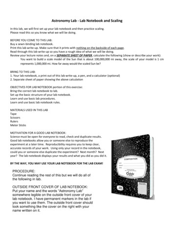
OutputPWM wave2PWMMessage SignalSawtooth ultViva Questions1. An audio signal consists of frequencies in the range of 100Hz to 5.5KHz.What is the minimumfrequency at which it should be sampled in order to transmit it through pulse modulation?2. Draw a TDM signal which is handling three different signals using PWM?3. What do you infer from the frequency spectrum of a PWM signal?4. Clock frequency in a PWM system is 2.5 kHz and modulating signal frequency is 500Hzhowmanypulses per cycle of signal occur in PWM output? Draw the PWM signal?5. Why should the curve for pulse width Vs modulating voltage be linear?6. What is the other name for PWM?7. What is the disadvantage of PWM?8. Will PWM work if the synchronization between Tx and Rx fails?9. Why integrator is required in demodulation of PWM?10. What kind of conversion is done in PWM generation?Department of Electronics & Communication EngineeringPage 61
Applications1.PWM is used in telecommunication systems.2.PWM can be used to control the amount of power delivered to a load without incurring the losses.So, this can be used in power delivering systems.3.Audio effects and amplifications purposes also used.4.PWM signals are used to control the speed of the robot by controlling the motors.5.PWM is also used in robotics.6.Embedded applications.7.Analog and digital applications etc.Department of Electronics & Communication EngineeringPage 62
12.Pulse Position Modulation & DemodulationAimTo simulate PPM modulation and demodulation using MATLAB.Apparatus Requireda) Hardware Tools: Computer systemb) Software Tool: MATLAB 7.0 or Upgraded VersionCode:clcclear all;close all;fc 50;fs 1000;f1 200;f2 300;t 0:1/fs:((2/f1)-(1/fs));x1 0.4*cos(2*pi*f1*t) 0.5;subplot(311);plot(x1);title('Message Signal'); grid;subplot(312);y modulate(x1,fc,fs,'ppm');plot(y);title('PPM MODULATION');grid;z emodulated o/p'); grid;Department of Electronics & Communication EngineeringPage 63
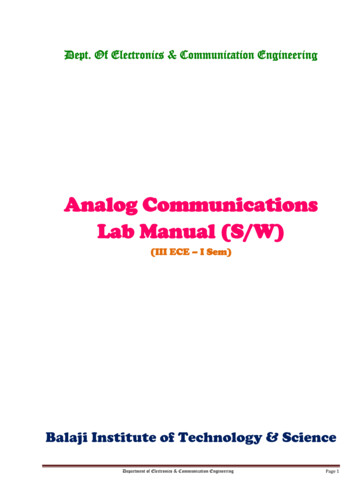
OutputMessage Signal10.50123456789101601802008910PPM MODULATION10.50020406080100120140Demodulated o/p10.501234567ResultViva Questions1. What is the advantage of PPM over PWM?2. Is the synchronization is must between Tx and Rx3. Shift in the position of each pulse of PPM depends on what?4. Can we generate PWM from PPM?5. Why do we need 555 timers?6. Does PPM contain derivative of modulating signal compared to PWM?7. For above scheme, do we have to use LPF and integrator in that order?8. If we convert PPM to PWM & then detect the message signal, will the o/p has less distortion?9. Is synchronization critical in PPM?10. How robust is the PPM to noise?Applications1.Used in non coherent detection where a receiver does not need any Phase lock loop for trackingthe phase of the carrier.2.Used in radio frequency (RF) communication.3.Also used in contactless smart card, high frequency, RFID (radio frequency ID) tags and etc.Department of Electronics & Communication EngineeringPage 64
Advantages of Pulse Position Modulation (PPM) Pulse position modulation has low noise interference when compared to PAM becauseamplitude and width of the pulses are made constant during modulation. Noise removal and separation is very easy in pulse position modulation. Power usage is also very low when compared to other modulations due to constant pulseamplitude and width.Disadvantages of Pulse Position Modulation (PPM) The synchronization between transmitter and receiver is required, which is not possible forevery time and we need dedicated channel for it. Large bandwidth is required for transmission same as pulse amplitude modulation. Special equipments are required in this type of modulations.Department of Electronics & Communication EngineeringPage 65
5. Used to transmit Morse code using radio and other communication systems. 6. Used in Navy and Aviation for communications as AM signals can travel longer distances. Advantages of Amplitude Modulation: Because of amplitude modulation wavelength, AM signals can propagate longer distances.