Transcription
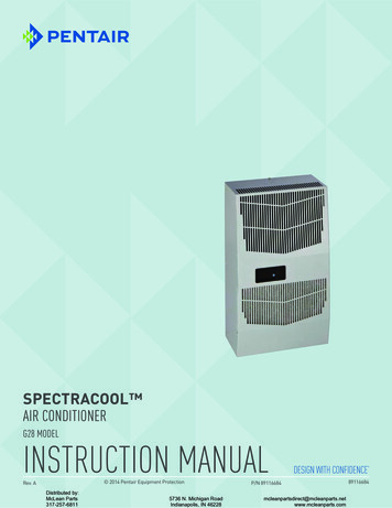
SPECTRACOOL Air ConditionerG28 ModelINSTRUCTION MANUAL 2014 Pentair Equipment ProtectionRev. ADistributed by:McLean Parts317-257-68115736 N. Michigan RoadIndianapolis, IN 46228P/N nparts.com89116684
TABLE OF CONTENTSRECEIVING THE AIR CONDITIONER.3HANDLING AND TESTING THE AIR CONDITIONER.3HOW TO READ MODEL NUMBERS.3TECHNICAL INFORMATION.4Sequence of Operation.4Heating.4Cooling.4Standard and Optional Component Operation.4Thermostat.4Remote Access Control (optional).4Head Pressure Control (optional).4Contactor (460V Units only).4Overload (460V Units only).4Phase Monitor.5460V to 230V Transformer.5115V/230V to 10V Transformer (optional).5115V/230V to 24V Transformer and Relay (optional).5Schematics and Wiring Diagrams for Thermostat Control.54000 BTU 1-Phase Schematic (actual unit options may vary).56000 BTU 1-Phase Schematic (actual unit options may vary).6G28 Generic 3-Phase Schematic (actual unit options may vary).64000 BTU 1-Phase Wire Diagram (actual unit options may vary).76000 BTU 1-Phase Wire Diagram (actual unit options may vary).8G28 Generic 3-Phase Wire Diagram (actual unit options may vary).9DIMENSIONAL DRAWINGS.104000 BTU 115V With Thermostats.106000 and 4000 BTU 230V With Thermostats.11G28 Generic 460V With Thermostats.11INSTALLATION INSTRUCTIONS.12REMOTE ACCESS CONTROL (optional).13INTRODUCTION.13ENERGIZING THE CONTROLLER.13CONTROL STATUS INDICATION.13DISPLAYING AND CHANGING PROGRAM VARIABLES.14OPERATING PARAMETERS.14ALARM PARAMETERS.14DISPLAYING TEMPERATURE SENSOR #2.14COMPRESSOR RESTART TIME DELAY.14ALARM OUTPUT CONTACT.14ALARM INPUT CONNECTION.15ALARM CONDITION DISPLAY.15AIR CONDITIONER UNIT COMMUNICATION FEATURES.15USB COMMUNICATION.15ETHERNET COMMUNICATION.15USING THE PC INTERFACE TOOL.16USB COMMUNICATION MODE.16ETHERNET COMMUNICATION MODE.17Remote Access Control Pin-out.18Schematics and Wiring Diagrams for Remote Access Control.194000 BTU 1-Phase Schematic (actual unit options may vary).196000 BTU 1-Phase Schematic (actual unit options may vary).19G28 Generic 3-Phase Schematic (actual unit options may vary).204000 BTU 1-Phase Wire Diagram for Remote Access Control (actual unit options may vary).216000 BTU 1-Phase Wire Diagram for Remote Access Control (actual unit options may vary).22G28 Generic 3-Phase Wire Diagram for Remote Access Control (actual unit options may vary) 23DIMENSIONAL DRAWINGS.244000 BTU 115V With Remote Access Control.244000 and 6000 BTU 230V With Remote Access Control.24INSTALLATION INSTRUCTIONS WITH REMOTE ACCESS CONTROL.25MAINTENANCE.26Compressor.26Inlet Air Filter.26How To Remove, Clean or Install a New Inlet Air Filter.26Condenser and Evaporator Air Movers.27Refrigerant Loss.27Refrigerant Properties Chart (R 407c).28Refrigerant Properties Chart (R 134a).28Functional Data.294000/6000 BTU Unit Characteristics.30SERVICE DATA.31Components List.31TROUBLE SHOOTING.32Basic Air Conditioning Trouble Shooting Check List - Thermostat Version.32Symptoms and Possible Causes - Thermostat Version.33Basic Air Conditioning Trouble Shooting Check List - Remote Access Control Version.34Symptoms and Possible Causes - Remote Access Control Version.36WARRANTY.38RETURN AND REPAIR POLICY.38LIMITATION OF LIABILITY.39-2-Distributed by:McLean Parts317-257-6811 2014 Pentair Equipment Protection5736 N. Michigan RoadIndianapolis, IN mcleanparts.com
RECEIVING THE AIR CONDITIONERInspect the air conditioner. Check for concealed damage that may have occurred during shipment. Look for dents,scratches, loose assemblies, evidence of oil, etc. Damage evident upon receipt should be noted on the freight bill.Damage should be brought to the attention of the delivering carrier -- NOT to Pentair Equipment Protection -within 15 days of delivery. Save the carton and packing material and request an inspection. Then file a claim withthe delivering carrier.Pentair Equipment Protection cannot accept responsibility for freight damages; however, we will assist you in anyway possible.HANDLING AND TESTING THE AIR CONDITIONERIf the air conditioner has been in a horizontal position, be certain it is placed in an upright, vertical or mountingposition for a minimum of five (5) minutes before operating.CAUTIONDo not attempt to operate the air conditioner while it is horizontalor on its side, back or front. The refrigeration compressor is filledwith lubricating oil. This will cause permanent damage to the airconditioner and also voids the warranty.TEST FOR FUNCTIONALITY BEFORE MOUNTING THE AIR CONDITIONER TO THE ENCLOSURE.Refer to the nameplate for proper electrical current requirements, and then wire the unit to a properly groundedpower supply using copper conductors only. Power supply wiring should be restrained after field installation toensure no contact with internal fan. Minimum circuit ampacity should be at least 125% of the amperage shown onthe unit nameplate. No other equipment should be connected to this circuit to prevent overloadingImmediately after applying power, the evaporator blower (enclosure air) should start running. Operate theair conditioner with the compressor running for five (5) to ten (10) minutes. You will need to set the coolingthermostat or controller setpoint below the ambient temperature to operate the compressor.Condenser air temperatures should be warmer than normal room temperatures within a few minutes after thecondenser impellers start.See Sequence of Operation on page 4 for specifics on how the unit operates when powered up.HOW TO READ MODEL NUMBERSG280646G150123451. Identifies the type/family of air conditioner and the approximate height (i.e. G28 Global familyabout 28 inch high).2. This is the air conditioner’s listed capacity in BTU/Hr. at rated conditions. (i.e. 06 6,000 BTU/Hr. at131/131 F)3. 1 115 Volt, 2 230 Volt, 4 460 Volt.4. 6 50/60 Hz or 60 Hz only.5. Unique set of numbers for each air conditioner which identifies the accessories on a model.89116684 Distributed by:McLean Parts317-257-6811 2014 Pentair Equipment Protection5736 N. Michigan RoadIndianapolis, IN parts.com
TECHNICAL INFORMATIONSEQUENCE OF OPERATIONThe air conditioner comes standard with two internally mounted thermostats or remote access control. Thereare two modes of operation; heating and cooling. During heating and cooling modes the evaporator fan will berunning.HEATINGWhen the enclosure temperature is below the heating thermostat setpoint, power is applied to theheaters. When the enclosure temperature is 10 degrees above the setpoint the heater is powered off.COOLINGWhen the enclosure temperature is above the cooling thermostat setpoint, power is applied through thethermostat. The compressor is then energized either directly or through a contactor if unit requires one.The condenser impellers will start immediately if the unit is not equipped with an optional head pressurecontrol switch. If the unit is equipped with an optional head pressure control switch, the condenserimpellers will start once the refrigerant pressure reaches the setting of the switch. Component specificinformation is listed below.Operating the air conditioner below the minimum ambient temperature or above the maximum ambienttemperatures indicated on the nameplate voids all warranties. DO NOT set the enclosure thermostat to atemperature lower than 70 F. Doing so can increase the likelihood of frost buildup on the evaporator coil.The moisture that the enclosure air can contain is limited. If moisture flows from the drain tubecontinuously this can only mean that ambient air is entering the enclosure. Be aware that frequentopening of the enclosure’s door admits humid air that the air conditioner must then dehumidify.STANDARD AND OPTIONAL COMPONENT OPERATIONTHERMOSTATThe standard G28 air conditioner uses our standard 10-1061-16 thermostat. The thermostat setpointequals the temperature that the air conditioner turns off. The thermostat has a 10 F differential fromsetpoint until it calls for cooling or heating. An example of operation is shown below.FOR COOLING (75-100 F RANGE): FOR HEATING (55-65 F RANGE):Thermostat setpoint 80 FCooling turns on at 90 FCooling turns off at 80 F Thermostat setpoint 55 FHeating turns on at 55 FHeating turns off at 65 FNOTE: For testing purposes only, the thermostat stop screw may be removed (on units soequipped) to allow settings below 70 F. After testing, replace the stop screw and verify thatthe thermostat cannot be set below 70 F. Extended operation below 70 F can cause coil freezeups resulting in reduced load and/or unit damage.REMOTE ACCESS CONTROL (OPTIONAL)See REMOTE ACCESS CONTROL (optional) on page 13HEAD PRESSURE CONTROL (OPTIONAL)Unit is set at the factory, no adjustment necessary.At a saturated condenser temperature of 85 F (95 psig), the condenser fans will power off. At a saturatedcondenser temperature of 118 F (165 psig), the condenser fans will power on.CONTACTOR (460V UNITS ONLY)The contactor on this model uses a 230V coil.OVERLOAD (460V UNITS ONLY)Set overload reset setting to automatic “A” and trip point dial to 1.6A.-4-Distributed by:McLean Parts317-257-6811 2014 Pentair Equipment Protection5736 N. Michigan RoadIndianapolis, IN mcleanparts.com
PHASE MONITORThis product is equipped with Phase/Voltage Protection. Please verify correct phasing and voltage beforeoperating. Note the fans may still operate if phasing is incorrect, but the compressor will not, so the unitwill not cool. Illuminated light on Phase Monitor indicates phase is correct.If the light is not illuminated, disconnect power from the unit and swap any two power leads at theterminal block. This should correct the phasing. The light should now illuminate when power is reapplied.460V TO 230V TRANSFORMERThe 230V from this transformer powers the fans, contactor and optional transformers. 460V is only usedto run the compressor.115V/230V TO 10V TRANSFORMER (OPTIONAL)This transformer powers the thermal display on thermostat controlled units only.115V/230V TO 24V TRANSFORMER AND RELAY (OPTIONAL)The transformer and relay are used to operate the condenser blower and compressor by using a customersupplied, remote mounted door switch. This is not a safety door switch, but rather, only helps to reducecondensation at the evaporator coil if the door is opened. The unit will remain electrified when the doorswitch is operated with the evaporator fan continuing to operate, and potentially, if temperatures are lowenough, the heater may continue to operate on outdoor models.SCHEMATICS AND WIRING DIAGRAMS FOR THERMOSTAT CONTROL4000 BTU 1-PHASE SCHEMATIC (ACTUAL UNIT OPTIONS MAY VARY)89116684 Distributed by:McLean Parts317-257-6811 2014 Pentair Equipment Protection5736 N. Michigan RoadIndianapolis, IN parts.com
6000 BTU 1-PHASE SCHEMATIC (ACTUAL UNIT OPTIONS MAY VARY)G28 GENERIC 3-PHASE SCHEMATIC (ACTUAL UNIT OPTIONS MAY VARY)-6-Distributed by:McLean Parts317-257-6811 2014 Pentair Equipment Protection5736 N. Michigan RoadIndianapolis, IN mcleanparts.com
4000 BTU 1-PHASE WIRE DIAGRAM (ACTUAL UNIT OPTIONS MAY VARY)8907728489116684 Distributed by:McLean Parts317-257-6811 2014 Pentair Equipment Protection5736 N. Michigan RoadIndianapolis, IN parts.com
6000 BTU 1-PHASE WIRE DIAGRAM (ACTUAL UNIT OPTIONS MAY VARY)89081439-8-Distributed by:McLean Parts317-257-6811 2014 Pentair Equipment Protection5736 N. Michigan RoadIndianapolis, IN mcleanparts.com
G28 GENERIC 3-PHASE WIRE DIAGRAM (ACTUAL UNIT OPTIONS MAY VARY)89116684 Distributed by:McLean Parts317-257-6811 2014 Pentair Equipment Protection5736 N. Michigan RoadIndianapolis, IN parts.com
DIMENSIONAL DRAWINGS4000 BTU 115V WITH THERMOSTATS : 50 ,5 287(1&/2685( ,5 ,1 &22/,1* ( 7,1*7 (50267 7632:(5 ,1/(7 5(029 %/( 1*,1*7 %6 0%,(17 ,5 ,1&22/ ,5 287 237,21 / &&(66 3 1(/ 21/ )25 81,76 :,7 ( 7(589076942&/( 1 %/( 5(86 %/( /80,180 ,1/(7 ),/7(5%( ,1' 5(029 %/( 3 1(/ 81& 02817,1* 2/(6127( 33529( 72 7 3( 5 02817,1* * 6.(7 6833/,(' 127 6 2:1 &&(66 2/( 72 2 ' '5 ,1 678%- 10 -Distributed by:McLean Parts317-257-6811 2014 Pentair Equipment Protection5736 N. Michigan RoadIndianapolis, IN mcleanparts.com
6000 AND 4000 BTU 230V WITH THERMOSTATS &22/,1* 7 (50267 732:(5 ,1/(7: 50 ,5 287(1&/2685( ,5 ,1 ( 7 7 (50267 7237,21 / 0%,(17 ,5 ,15(029 %/( 1*,1*7 %6 &22/ ,5 287 237,21 / &&(66 3 1(/ 21/ )25 81,76 :,7 ( 7(5 &/( 1 %/( 5(86 %/( /80,180 ,1/(7 ),/7(5%( ,1' 5(029 %/( 3 1(/ 88026303 81& 02817,1* 2/(6127( 33529( 72 7 3( 5 02817,1* * 6.(7 6833/,(' 127 6 2:1 &&(66 2/( 72 @ 2 ' '5 ,1 678%G28 GENERIC 460V WITH THERMOSTATS.982515.05382.2.65 8.9123.2WARMAIR OUTENCLOSUREAIR IN11.38288.915.87403.114.20360.6COOLING 50165.1(2)28.59726.2AMBIENTAIR INREMOVABLEHANGINGTABS19.32490.7POWER INLET6.13155.76.30160COOLAIR OUT6.87174.5(2)5.52140.2OPTIONAL ACCESS PANEL(ONLY FOR UNITS WITH HEATER)1.2631.9CLEANABLE, REUSABLEALUMINUM INLET FILTERBEHIND REMOVABLE PANEL.8905947914.00355.61/4-20 UNC (11)MOUNTING HOLES15.26387.6NOTE:1.APPROVE TO TYPE 3R/4/12.2.MOUNTING GASKET SUPPLIED (NOT SHOWN).ACCESS HOLE TO.375 [9.5] O.D. DRAIN STUB89116684 Distributed by:McLean Parts317-257-6811 2014 Pentair Equipment Protection5736 N. Michigan RoadIndianapolis, IN 46228- 11 om
INSTALLATION INSTRUCTIONS1. Inspect the air conditioner and verify correct functionality before mounting the air conditioner. SeeHANDLING AND TESTING THE AIR CONDITIONER on page 3.2. Using the mounting gasket kit provided with the unit, install gaskets to the air conditioner, seeFigure 1.3. Mount air conditioner on enclosure taking care not to damage the mounting gasket. Themounting gasket is the seal between the air conditioner and the enclosure. Avoid dragging the airconditioner on the enclosure with the mounting gasket attached as this could cause rips or tearsin the gasket and risk losing the water tight seal.4. Allow unit to remain upright for a minimum of five (5) minutes before starting. CAUTION! Airconditioner must be in upright position during operation.5. Refer to the nameplate for electrical requirements. Wire the unit to a properly grounded powersupply. For 3 phase units, once power is applied, verify that phase monitor light is illuminatedwhich indicates correct electrical phasing. Electrical circuit should be fused with slow blow orHACR circuit breaker.6. Some air conditioners require a remote mounted thermostat. Wire the thermostat outputs to theappropriate terminals on the 24 VAC terminal strip by noting the locations on the correct wiringdiagram.7. Set thermostat for required cabinet temperature. Refer to Sequence of Operation on page 4 forth
CONTACTOR (460V UNITS ONLY) The contactor on this model uses a 230V coil. OVERLOAD (460V UNITS ONLY) Set overload reset setting to automatic "A" and trip point dial to 1.6A. Distributed by: McLean Parts 317-257-6811 5736 N. Michigan Road Indianapolis, IN 46228 mcleanpartsdirect@mcleanparts.net www.mcleanparts.com