Transcription
DesignCAD 3D Max 2016.1 Release NotesOct. 6, 2016DesignCAD 3D Max 2016.1 (internal version number 26.1) has the following changes and improvements.Insert ManagerWith the initial release of DesignCAD 2016, we introduced a new feature, the Insert Manager. This hasundergone further refinement since the initial release.The dialog box has been rearranged to make more efficient use of the space available, going from this:toThe newer dialog box is slightly taller by default, but shows more preview icons and allows for a tallerpreview window of the selected item. Otherwise the dialog box functions much like the previousversion.New capabilities of the Insert Manager: Now you can double-click on a preview icon to immediately open that symbol or block in theBlock Editor (note that images cannot be edited in DesignCAD, so double-clicking on an imagehas no effect).After opening the Block Editor from the Insert Manager, when you subsequently exit the BockEditor the just-edited block or symbol remains highlighted in the Insert Manager.
When you right-click on the preview list panel and sort by Reference Count, the sort is now indescending order (i.e. from most-referenced to least-referenced).Changes to Block Editor Mode: It is now possible to update the handles of a symbol or the insertion point of a block in the BlockEditor using Point/Set Drawing Handles. To see where the current insertion point and/orhandles are, use Point/Show Drawing Handles. Note: After you change the handles of a symbolor block, all existing instances of the symbol/block are updated to match; however, the existinginstances of a modified symbol do not change scale, even if you modified the distance betweenthe first and second handles of the symbol. In such cases only the position and orientation areupdated in existing instances. When you insert new instances of the modified symbol, anduncheck "Use original scale", the scale is adjusted relative to the new handles.While editing a block or symbol, the name of the block or symbol now appears in the title bar,along with a "Symbol/Block Editor Mode" indicator. Example:"DesignCAD 3D Max 2016 64-bit – [Symbol/Block Editor Mode: SomeSymbolName.dcd: main]"The Block Editor can now only be exited using File/Save Changes and Exit or File/CancelChanges and Exit. It is no longer possible to switch to another open drawing while in BlockEditor Mode.Now when you exit the Block Editor, the drawing screen is restored to the view state it was inbefore entering the Block Editor.The Info Box now has an "Edit Content" button for selected symbols or blocks, which allows youto enter the Block Editor directly from the Info Box for a selected Symbol (embedded only) orBlock. If an externally-linked ("by reference") symbol is selected, the Edit Content button isgrayed out and does nothing.Other Changes: There was a problem when printing Solid Surface objects – they were omitted from shadedprints. Now they are printed correctly.When typing into an editable field in the Info Box, the first character was sometimes beingdropped. This has been corrected.Ctrl-C, Ctrl-X, and Ctrl-V shortcut keys (Copy, Cut, Paste) weren't working in the Info Box fields.Now they do again.Wide-line arrows were not printing correctly from Paperspace Mode. Now they do.STL Import now has a "match current coordinate system" option. If this is checked, imported STLfiles will reverse the sign of the Z-coordinate when imported into a left-hand drawing. If thedrawing is using right-hand coordinates, the Z-coordinates are not altered. This should helpprevent mirroring of STL files from other software. To access this option, run the File/Import
command, select STL as the import format, and click the 'Setup' button in the Import dialog box. STL Export now has a "force right-hand coordinates" option. If this is checked, exported STL filesreverse the signs of all z-coordinates when left-hand coordinate are active. This will help preventmirroring of the object when viewed in other software. To access this option, run the File/Exportcommand, select STL (Stereolithography) as the export format, and click the 'Setup' button in theExport dialog box. When a symbol or block included features in a magenta color, those features weren't visible inthe Insert Manager's preview panel. This has been corrected.When drawing Balloon annotations with a Text Size of 2 or larger and more than two points inthe arrow, the text always moved to the second point of the arrow, rather than always centeringin the balloon. Now the text always centers in the balloon as it should.If DesignCAD was started by double-clicking on the drawing rather than using File/Open,sometimes using the Rotate command on text entities could cause a crash.After importing certain DWG files into DesignCAD, the Fixed Text option on some dimensionswas checked, and the numeric dimension text did not show, only the units.Using Tools/Purge Unused Blocks from an active papers pace template would improperlyremove all blocks that weren't used directly in that template. Now Purge Unused Blocksproperly checks for usage in model space and other paper space templates before deleting ablock.We fixed a problem that could prevent a wireframe animation from being exported if EnableOffscreen Bitmap was unchecked in View Options.We fixed some display problems in Animation Mode when Enable Offscreen Bitmap wasunchecked and the animation view was switched from OpenGL shaded to Wireframe.
We fixed a 64-bit version problem where pressing the Enter key would not end 'incomplete'commands as it did in the 32-bit version.When Flicker-Free GDI Draw was enabled, moving objects in a 3D OpenGL-Shaded or OpenGLHidden view was leaving display artifacts. This has been corrected.When using OpenGL Hidden Line or Shaded modes, unchecking the boxes to display Arrows,Lines, Dimensions and Text had no effect – they still appeared in the hidden or shaded view.Now they are correctly displayed or not according to how the options are set in the Shade andHide dialog box.Under some circumstances, after saving a drawing with Progressive Dimensions, the arrowswould swap direction after the drawing was re-opened.SPECIAL NOTE ABOUT CUSTOM PROPERTIESWarning: When a drawing from version 2016 contains custom properties, it cannot be opened reliablyin older versions of DesignCAD. To use such a drawing in version 25 or earlier, be sure to use File/SaveAs to save it to an older version format. If you do open a V2016 drawing in an older version, every entityincluding and after the first one with custom properties will be skipped; thus the drawing is very likely tobe incomplete.There is already a warning message that appears anytime you open a newer drawing in an older versionof DesignCAD. Heed the warning! If and when it pops up, understand that if you proceed with openingthe drawing anyway, you run the risk of losing drawing data.
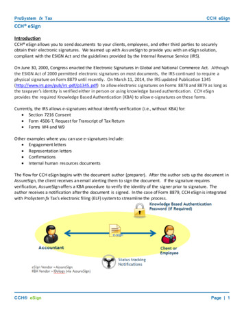
DesignCAD 3D Max 2016 Release NotesJuly 20, 2016Thanks for purchasing, or upgrading to, DesignCAD 3D Max 2016. Here is a detailed look at what's newin this version.New Import/Export featureSketchUp Import – DesignCAD 2016 can now import SketchUp drawings. SketchUp versionsthrough SketchUp 2015 are currently supported. When importing SketchUp drawings, each separatesolid object is imported as a distinct Solid Surface entity in DesignCAD.The SketchUp Import Setup dialog includes a Transpose Y and Zoption. When checked, this allows SketchUp objects imported intoDesignCAD to appear "right side up". This option is providedbecause DesignCAD uses Y for the vertical axis, whereas SketchUpuses Z for the vertical axis. If this option is left unchecked,SketchUp imports will appear on their sides instead of upright.Insert ManagerFile/Insert Manager is a new command that allows the user to review and manage all blocks,symbols, and image files that are reference by or embedded in the drawing.When the Insert Manager command is run, a dialog box appears with three tabs, one each for Blocks,Images, and Symbols.BlocksThe Blocks tab shows a visual list of all blocks that are present in the drawing. When a single block ishighlighted by clicking on it, a larger preview is displayed below the list. Beneath the larger view is moreinformation about the block: its Name, ID, and a Reference Count.Right-clicking on the list of symbol icons displays a context menu for sorting the blocks. Blocks may besorted by Name, ID, or Reference Count.Right-clicking on the Name line gives you the option of copying the name to the clipboard.Right-clicking on the Symbol ID line gives you the option of copying the id to the clipboard (perhaps foruse in a macro or COM program).The Reference Count line shows three different values: -- Direct, Indirect, and In Definitions. The Directcount represents the number of times the block is included in the drawing as a stand-alone block (i.e.
not as part of another block or symbol). The Indirect count indicates how many times the block isincluded in other blocks or symbols that are included in the drawing. The In Definitions count showshow many block or symbol definitions include the block as part of that definition.Right-click on this References line for a more detailed view of how the block is used; a context menuappears with the same categories: Direct, Indirect, and In Definitions.Expanding the Direct category will indicate if the block is in use by the drawing's Model Space viewand/or by one or more Paper Space layouts. Expanding the Indirect category will show which symbolsand/or blocks are in active use that include this block. Expanding the In Definitions category will indicate
which symbols and/or blocks include this block, whether or not there are any active references to thosesymbols/blocks.The Blocks tab of the Insert Manager offers three editing operations: Open in Block Editor, Delete, andInsert.Clicking on the Insert button will run the Block Insert command, and show the Block Insert dialog boxwith the highlighted block already selected.Clicking on the Delete button will allow you to delete all instances of the highlighted block from thedrawing, as well as the underlying block definition. Once this change is applied, the deletion cannot beundone.Clicking on the Open in Block Editor button will open a special view window with a limited menu andcommand list. While in the Block Editor, you can make almost any changes to the block definition thatyou desire, without the distraction of other drawing entities. See Block Editor below.ImagesThe Images tab of the Insert Manager is quite similar to the Blocks tab, showing all raster images thathave been added to the drawing. Most of the options for Images are the same as for Blocks. Images alsocontain a Path field, an Index field, and an Embedded field, and these are additional sort options if youright-click on the thumbnail list at the top.The Path field indicates the full path and filename of the original image. For embedded images, thisoriginal file may no longer exist in the referenced location. Right-clicking on the Path field allows you tocopy the full path and filename to the clipboard for later reference.The Index field indicates the index of the image in the list of images, i.e. the relative order in which theimage was originally added to the drawing.The Embedded field indicates whether the image is stored completely in the drawing (Yes) or is only areference to an external file (No). Blocks are always embedded, so this button is hidden on the Blockspage.If a Referenced image is highlighted in the visual list, the Embed in Drawing button becomeshighlighted. Clicking on this button allows a referenced image to be embedded in the drawing, so thatthe external image file is no longer necessary. This also changes the Embedded field from No to Yes.Note that the original image file must be present in the specified path for this to work.
SymbolsThe Symbols tab of the Insert Manager has the same features as the Images tab, and also has the Openin Block Editor button just like the Blocks tab.
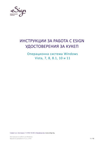
Block EditorWhen you highlight a symbol or block in the Insert Manager and click Open in Block Editor, the contentsof the block or symbol are displayed in a separate window, with no other entities in view. This BlockEditor mode has a somewhat limited set of drawing and editing commands; there is no access to loadingsymbols or blocks via the File menu, no print command, no options to save the symbol or block as anexternal file, and no access to special modes like Paper space Mode or Animation and WalkthroughModes. There is also no access to the Help or Window menu commands, and the Options command hasno effect. Aside from these exceptions, most other drawing and editing commands are available to youin the Block Editor.If you wish to modify the insertion point of a block or the handles of a symbol while in the Block Editor,use the Point/Show Drawing Handles command to display the existing handle(s) of the block or symbol.Use the Point/Set Drawing Handles command to change the existing handle(s) to new locations.If you need to add a symbol or block to one that you plan to edit, this cannot be done through the BlockEditor's File menu. Instead, first select the block or symbol to be added in the main drawing window andcopy it to the clipboard. Then you can open the symbol or block in the Block Editor and paste in theadditional content. Care should be taken, however, not to paste a copy of a block or symbol into itselfwhile it is being edited – this causes a circular reference, and may result in any number of difficultproblems.To discard the changes made in the Block Editor, choose File/Cancel Changes and Exit. To save thechanges made to a block or symbol in the Block Editor, choose File/Save Changes and Exit.The Insert Manager and the Block Editor are available in both Model Space and Paper Space. However,you may find some blocks and symbols difficult to edit while in Paper Space Mode, due to the limiteddrawing area that is available in that mode. If you have difficulties editing a particular block or symbol inPaper Space Mode, try exiting to Model Space and editing it there.Custom PropertiesDesignCAD now supports the addition of custom properties to drawings and to drawing entities.Custom Properties are bits of text that are identified by a combination of a Key and a Name field. This isa means of adding "invisible" text information to a drawing or an object. These custom properties canbe viewed and edited manually by means of a Custom Properties dialog, or processed by code viaBasicCAD macros or OLE Automation programs.Drawing Custom Properties are accessed via the File/Document Custom Properties command.Entity Custom Properties are accessed via the Custom Properties button in the Info Box. Either methodopens a Custom Properties editor:
The dialog shows four fields: Index, Key, Name, and Value. The Index is simply the order in which eachcustom property was added. The Key is one of two fields that uniquely identify each custom property.The Name field is the second field used to identify a custom property. The Value field is the "contents"of the custom property.A new Custom Property may be added using the Add Custom Property button.No two custom properties for a given drawing or drawing entity may have the same Key/Namecombination. Two different drawings may have identical Key/Name pairs, and a drawing and one ormore entities contained within it may have the same Key/Name pairs; the restriction only applies for theset of custom properties in use by a particular drawing or a particular drawing entity.
A single custom property can be selected by left-clicking on it. More can be selected using Ctrl-left-clickor by Shift-left-click or Shift-down-arrow. Once one or more custom properties are selected in theCustom Properties editor, they can be deleted using the Delete Selected Properties button. The DeleteAll button will delete all custom properties that have been added via this editor.Note, however, that some custom properties that were added via BasicCAD or OLE Automation may notbe editable. Any such non-editable custom properties will have a gray background, and can only beedited or deleted using BasicCAD or OLE Automation methods.Accessing custom properties via BasicCAD and OLE Automation is described below.Custom Properties of drawing objects are duplicated when these objects are copied and pasted,duplicated, arrayed, or trimmed. (Note: any non-editable properties are NOT duplicated in this way.)When you Explode a compound drawing object (such as a dimension or grid) that contains customproperties, the exploded pieces will no longer contain those properties. Similarly, Combine Lines causesthe resulting object to lose any custom properties that may have been in its component pieces.Custom Properties of drawings are saved with the drawing when you use Save, Save As, Save a Copy, orSave as Symbol; however, they are not transferred into a host drawing if you use Symbol Load.
Other Changes in DesignCAD 2016Flicker-Free GDI DrawA new option has been added to the View Options panel – Flicker-Free GDI Draw. When this option isselected, DesignCAD uses special optimizations to speed up the draw of wide lines in GDI wireframeviews. This option has no effect when RedSDK Mode is active. To access this setting press the 'Q' key toopen the Options panel, and activate the 'View' tab. The checkbox is on the bottom right of the Displayoptions group. The difference is particularly notable under Windows 7 if you have transparency enabled.General Fixes and Improvements: When exporting files to DWG or DXF format, sometimes angled text would be converted tohorizontal text. This has been fixed.The Scan Image command sometimes was grayed out because DesignCAD couldn't find thenecessary program. This has been fixed.When applying a material (such as Oak, Cherry, Pearl, etc.) to a Solid Surface entity, the materialwas not saved with the object when the drawing was saved.Save as 2D Projection was not working with Solid Surface entities.Working with multi-lines could sometimes crash DesignCAD.
BasicCAD Additions for Custom PropertiesSTATEMENT: ADDPROPERTY entid, key , name , value , nocopyArguments: entid – a number. If entid is greater than zero it represents the index of the entity to which thenew property is to be added. If entid is 0, the property will be added to the drawing instead.key -- a string representing the key to be used in identifying this custom property.name – a string representing the name to be used in identifying this custom property.value – a string representing the contents of the property.nocopy – a flag that indicates whether this custom property should be propagated from theoriginal entity via Duplicate, Copy/Paste, Array, or other editing operations. Also, if set, does notallow editing or deletion of this property via the Custom Property editor.The ADDPROPERTY statement adds a new custom property to the specified entity if entid 0, or to thedrawing if entid 0.Errors: If the key/name pair clashes with an already-defined custom property, the statement triggersError 114.If entid is non-zero and does not specify a legal entity id, the statement triggers Error 60.Example 1:' add a custom property to the first selected entityPRECISION 0ON ERROR GOTO oopsGETSELECT 1, entidkey "PART"name "NUMBER"value "ZX 500 A12"nocopy 0 'false – this custom property can be edited by the drawing's user.ADDPROPERTY entid, key , name , value , nocopyENDoops:e Error(q) ' get error numberMESSAGE "Error", e, "; ", Err (e)RETURNExample 2:' add a custom property to the drawingentid 0 ' specifies the drawing instead of an entitykey "DRAWING"name "START DATE"value "06/25/2016"nocopy 0 'false – this custom property can be edited by the drawing's user.ADDPROPERTY entid, key , name , value , nocopy
STATEMENT: GETPROPERTY entid, propid, key , name , value , nocopyArguments: entid – a number. If entid is greater than zero it represents the index of the entity from whichthe property is to be retrieved. If entid is 0, the property will be retrieved from the drawinginstead.propid – a number specifying the index of the property to be retrieved. Indexing begins at 1, not0.key -- a string that will contain the key of this custom property.name – a string representing the name of this custom property.value – a string representing the contents of this custom property.nocopy – a flag that indicates whether this custom property can be propagated from the originalentity via Duplicate, Copy/Paste, Array, or other editing operations. Also, if set, does not allowediting or deletion of this property via the Custom Property editor.The GETPROPERTY statement retrieves a custom property from the specified entity if entid 0, or fromthe drawing if entid 0.Errors: If entid is non-zero and does not specify a legal entity id, the statement triggers Error 60.If propid is not the index of an existing property, the statement triggers Error 25.Example 1:' get the third custom property from the first selected entitye 0PRECISION 0ON ERROR GOTO oopsGETSELECT 1, entidpropid 3key "aaaa"name "bbbb"value "cccc"nocopy -1GETPROPERTY entid, propid, key , name , value , nocopyIF e 0 THENMESSAGE "Property", propid, "KEY:", key , "; NAME:", name , ";VALUE: ", values , "; nc: ", nocopyEND IFENDoops:e Error(q) ' get error numberMESSAGE "Error", e, "; ", Err (e)RETURN
STATEMENT: SETPROPERTY entid, propid, key , name , value , nocopyArguments: entid – a number. If entid is greater than zero it represents the index of the entity for which theproperty is to be changed. If entid is 0, the indexed drawing property will be changed instead.propid – a number specifying the index of the property to be changed. Indexing begins at 1, not0.key -- a string that will contain the new key of this custom property.name – a string representing the new name of this custom property.value – a string representing the new contents of this custom property.nocopy – a flag that indicates whether this custom property can be propagated from the originalentity via Duplicate, Copy/Paste, Array, or other editing operations. Also, if set, does not allowediting or deletion of this property via the Custom Property editor.The SETPROPERTY statement modifies a custom property from the specified entity if entid 0, or fromthe drawing if entid 0.Errors: If entid is non-zero and does not specify a legal entity id, the statement triggers Error 60.If propid is not the index of an existing property, the statement triggers Error 25.If key and name would clash with an already-existing property, the statement triggers Error114.Example 1:' Set the third custom property in the drawinge 0PRECISION 0ON ERROR GOTO oopsentid 0 'we're targeting a drawing property instead of an entity propertypropid 3key "NewKey"name "NewName"value "I have changed."nocopy 1SETPROPERTY entid, propid, key , name , value , nocopyIF e 0 THENGETPROPERTY entid, propid, nkey , nname , nvalue , nncMESSAGE "Updated Property", propid, " KEY:", nkey , "; NAME:", nname ,"; VALUE: ", nvalues , "; nc: ", nncEND IFENDoops:e Error(q) ' get error numberMESSAGE "Error", e, "; ", Err (e)RETURN
STATEMENT: GETPROPERTYINDEX entid, name , startindex, foundindexArguments: entid – a number. If entid is greater than zero it represents the index of the entity to besearched. If entid is 0, the drawing properties will be searched instead.name – a string representing the custom property name to be searched for.startindex – a number representing which property index to start at.foundindex – a number representing the index of the next property that matches the specifiedname. Set to -1 if no matching property is found.The GETPROPERTYINDEX statement searches the custom properties of the drawing (if entid is 0), or ofthe specified entity (if entid 0) for a name field matching name . Set startindex to 1 to begin searchingat the first custom property. If searching for multiple matches (which is possible, since there may be twoor more properties with different key fields but the same name field), search for the second andsubsequent matches by adding 1 to the last foundindex.Errors: If entid is non-zero and does not specify a legal entity id, the statement triggers Error 60.If startindex is not the index of an existing property, the statement triggers Error 25.Example 1:' Search the drawing for all custom properties having the name "PARTNO"entid 0name "PARTNO"startindex 1foundindex 0PRECISION 0ON ERROR GOTO oopsDO WHILE foundindex 0GETPROPERTYINDEX entid, name , startindex, foundindexIF e 0 THEN GOTO finishIF foundindex -1 ThenMESSAGE "Match at index", foundindexStartindex foundindex 1END IFLOOPfinish:ENDoops:e ERR(q)RESUME NEXT
STATEMENT: DELETEPROPERTY entid, propidArguments: entid – a number. If entid is greater than zero it represents the index of the entity from which acustom property is to be deleted. If entid is 0, a custom property will be deleted from thedrawing properties instead.propid – the index of the custom property to be deleted.The DELETEPROPERTY statement deletes the custom property specified by propid from the entityspecified by entid, or from the drawing if entid is zero.Errors: If entid is non-zero and does not specify a legal entity id, the statement triggers Error 60.If propid is not the index of an existing property, the statement triggers Error 25.Example 1:' Delete the fourth custom property from entity 2entid 2propid 4DELETEPROPERTY entid, propidNew Sys() functions relating to Custom PropertiesSys(689) – the number of custom properties that the current drawing contains.Sys(690) – the number of custom properties contained in the entity last loaded by the ENTITYstatement.
OLE Automation Classes, Methods, and Properties for Custom PropertiesCustomProperties ClassMethods:AddProperty(Key , Name , Value , bNoCopy) as IntegerReturns the index of the newly-added property if successful, or -1 in case of failure.DeleteProperty(iIndex) as BooleanReturns True if successful or False if the property could not be deleted for any reason.Item(iIndex) as CustomPropertyReturns the CustomProperty specified by the index.Properties:Count as LongReturns the number of custom properties in the collectionCustomProperty ClassMethods:SetKey(Key ) as BooleanSets the Custom Property's Key to the value specified in Key . Returns False if the key could not beupdated to the specified value (typically due to a key/name clash that would result).SetName(Name ) as BooleanSets the Custom Property's Name to the value specified in Name . Returns False if the Name could notbe updated to the specified value (typically due to a key/name clash that would result).Properties:Key as String (read-only)Returns the Key for the Custom Property. Read-only. To change the contents of the Key property, usethe SetKey method.Name as String (read-only)Returns the Name for the Custom Property. Read-only. To change the contents of the Name property,use the SetName method.Data as String (read/write)Returns the Data contents for the Custom Property. Can be directly read and written.NoCopy as BooleanReturns the NoCopy field of the Custom Property. Can be set directly read and written.
esign A 3 ax 2016 Release otes July 20, 2016 Thanks for purchasing, or upgrading to, DesignCAD 3D Max 2016. Here is a detailed look at what's new in this version. New Import/Export feature Sk