Transcription
DESIGN AND RATINGSHELL AND TUBEHEAT EXCHANGERSBy John E. Edwards
Design and Rating ofShell and Tube Heat talsBasic TheoryHeat Transfer Model Selection3.0Design GuidelinesAppendicesIThermal Design Models SynopsisIICC-THERM User GuidelinesIIIThermal Model SelectionIVShortcut Heat Exchanger DesignVTEMA Heat Exchanger Layout DesignationVITypical Overall Heat Transfer CoefficientsVIITypical Resistance Fouling CoefficientsVIIILMTD Correction Factor FtIXWolverine Tube General DetailsXMidland Wire Cordage Turbulator DetailsXITube Dimensional DataXIIShell Tube Count DataReferences1.Hewitt,G.F. et al (1994) Process Heat Transfer, (CRC Press)2.Perry,R.H. and Green, D. (1984) Perry’s Chemical Engineers Handbook, 6th edition (McGraw Hill)3.Kern,D.Q. (1950) Process Heat Transfer (McGraw Hill)4.Coulson,J.M. and Richardson,J.F. (1993) Chemical Engineering Vol 1, 4th edition (Pergamon)5.Skinnet,R.K. (1993) Coulson & Richardson’s Chemical Engineering Vol 6, 2nd edition (Pergamon)6.Chemstations,Inc. CHEMCAD THERM Version 5.1 User Guide7.Schlunder,E.U. (1993) VDI Heat Atlas (Woodhead Publishing)8.Seider,D.S., Seader,J.D.Seader and Lewin,R.L. Process Design Principles, (John Wiley & Sons, Inc.)[ C20]References of this type are to be found in CC-THERM Help AppendixPAGE 2 OF 30MNL 032A Issued 29 August 08, Prepared by J.E.Edwards of P & I Design Ltd, Teesside, UKwww.pidesign.co.uk
Design and Rating ofShell and Tube Heat Exchangers1. 0IntroductionShell and tube heat exchangers are used extensively throughout the process industry and as such a basic understandingof their design, construction and performance is important to the practising engineer.The objective of this paper is to provide a concise review of the key issues involved in their thermal design without havingto refer to the extensive literature available on this topic.The author claims no originality but hopes that the format and contents will provide a comprehensive introduction to thesubject and enable the reader to achieve rapid and meaningful results.The optimum thermal design of a shell and tube heat exchanger involves the consideration of many interacting designparameters which can be summarised as follows:Process1.2.3.4.5.Process fluid assignments to shell side or tube side.Selection of stream temperature specifications.Setting shell side and tube side pressure drop design limits.Setting shell side and tube side velocity limits.Selection of heat transfer models and fouling coefficients for shell side and tube side.1.2.3.4.5.Selection of heat exchanger TEMA layout and number of passes.Specification of tube parameters - size, layout, pitch and material.Setting upper and lower design limits on tube length.Specification of shell side parameters – materials, baffle cut, baffle spacing and clearances.Setting upper and lower design limits on shell diameter, baffle cut and baffle spacing.MechanicalThere are several software design and rating packages available, including AspenBJAC, HTFS and CC-THERM, whichenable the designer to study the effects of the many interacting design parameters and achieve an optimum thermaldesign. These packages are supported by extensive component physical property databases and thermodynamicmodels.It must be stressed that software convergence and optimisation routines will not necessarily achieve a practical andeconomic design without the designer forcing parameters in an intuitive way. It is recommended that the design bechecked by running the model in the rating mode.It is the intention of this paper to provide the basic information and fundamentals in a concise format to achieve thisobjective.The paper is structured on Chemstations CC-THERM software which enables design and rating to be carried out within atotal process model using CHEMCAD steady state modelling software.However the principles involved are applicable to any software design process.In the Attachments a Design Aid is presented which includes key information for data entry and a shortcut calculationmethod in Excel to allow an independent check to be made on the results from software calculations.Detailed mechanical design and construction involving tube sheet layouts, thicknesses, clearances, tube supports andthermal expansion are not considered but the thermal design must be consistent with the practical requirements.Source references are not indicated in the main text as this paper should be considered as a general guidance note forcommon applications and is not intended to cover specialist or critical applications. Sources for this paper have beenacknowledged where possible.The symbols, where appropriate, are defined in the main text. The equations presented require the use of a consistentset of units unless stated otherwise.PAGE 3 OF 30MNL 032A Issued 29 August 08, Prepared by J.E.Edwards of P & I Design Ltd, Teesside, UKwww.pidesign.co.uk
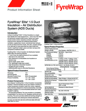
Design and Rating ofShell and Tube Heat Exchangers2. 0FundamentalsThe basic layout for a countercurrent shell and tube heat exchanger together with the associated heat curve for acondensing process generated from CHEMCAD are shown below:PAGE 4 OF 30MNL 032A Issued 29 August 08, Prepared by J.E.Edwards of P & I Design Ltd, Teesside, UKwww.pidesign.co.uk
Design and Rating ofShell and Tube Heat Exchangers2. 1Basic TheoryThe fundamental equations for heat transfer across a surface are given by:Q U A Δ T lm w C p ( t ) (t 2 t 1 ) W C p ( s ) (T1 T 2 )WhereorW LQ heat transferred per unit time(kJ/h, Btu/h)U the overall heat transfer coefficient (kJ/h-m2 oC, Btu/h-ft2-ºF)22Aheat-transfer area(m , ft )Δt lm log mean temperature difference (oC, ºF)Cp(s) liquid specific heat shell side (kJ/kg-ºK, Btu/lb-ºF)Cp(t) liquid specific heat tube side,wtube side flowWshell side flow(kg/h, lb/h)The log mean temperature difference ΔTlm (LMTD) for countercurrent flow is given by:ΔTlm Where T1T2t1t2(T1 t 2) (T2 t1)(T1 t 2)ln ( )T 2 t1inlet shell side fluid temperatureoutlet shell side fluid temperatureinlet tube side temperatureoutlet tube-side temperatureIn design, a correction factor is applied to the LMTD to allow for the departure from true countercurrent flowto determine the true temperature difference.Δ Tm F t Δ TmThe correction factor is a function of the fluid temperatures and the number of tube and shell passes and iscorrelated as a function of two dimensionless temperature ratios(t 2 t1)S ( )T1 t1(T1 T2 )R ( )t 2 t1Kern developed a relationship applicable to any heat exchanger with an even number of passes and generatedtemperature correction factor plots; plots for other arrangements are available in the TEMA standards.The correction factor Ft for a 1-2 heat exchanger which has 1 shell pass and 2 or more even number of tubepasses can be determined from the chart in the Appendix VIII and is given by:The overall heat transfer coefficient U is the sum of several individual resistances as follows:11 1111 U h i hfi k x ho hfoThe combined fouling coefficient hf can be defined as follows:hf hfi hfohfi hfoThe individual heat transfer coefficients depend on the nature of the heat transfer process, the stream properties and theheat transfer surface arrangements. The heat exchanger layout depends on the heat transfer area (HTA) so an initialestimate is required based on a trial value of the OHTC.CHEMCAD is used to establish the steady state mass and energy balances across the heat exchanger and typicalvalues of the OHTC are shown in the Attachments. A quick calculation method XLTHERM is also available to assist thisprocedure. The fouling factors chosen can have a significant effect on the design and again typical values are shown inthe Attachments.PAGE 5 OF 30MNL 032A Issued 29 August 08, Prepared by J.E.Edwards of P & I Design Ltd, Teesside, UKwww.pidesign.co.uk
Design and Rating ofShell and Tube Heat Exchangers2.2Heat Transfer Model SelectionThe heat transfer model selection is determined by the heat transfer process (sensible, condensing, boiling), thesurface geometry (tube-side, shell-side), the flow regime (laminar, turbulent, stratifying, annular), and the surfaceorientation (vertical, horizontal).A heat transfer model selection flow chart is presented in the Appendix IV to assist in this procedure. This flow chartindicates all the models available in CC-THERM and shows the default selections.A synopsis of the various heat transfer models together with their conditions of application is given in Appendix I.The key features of the models are summarised below:Shellside Film Coefficient Methods for Single Component Condensation in Laminar FlowThe Nusselt Method is used for horizontal condensation under stratifying conditions where the liquid film is drainingunder gravity with minimum influence due to vapour shear. This is the CC-THERM default method.The Eissenberg Method is applicable to condensation over tube banks and considers condensate layer thickeningbehaviour. This provides the most conservative heat transfer coefficient prediction as compared to the Nusselt and Kernmethods for condensation over a single tube.Range of application is for Reynolds Numbers to be in the range 1800 to 2000.The Kern MethodKern adapted the Nusselt equation to allow evaluation of fluid conditions at the film temperature.This method requires the film to be in streamline flow with a Reynolds Numbers range 1800 to 2100.Shellside Film Coefficient Methods for Single Component Condensation in Turbulent FlowThe Colburn Method is based on a correlation of industrial data for a wide range of fluids in heat exchangers usingstandard tube pitch designs.Range of application is for Reynolds Numbers to be in the range 2000 to E06 gives results with a deviation 20% safe. Itprovides a good method for the verification of computer derived heat transfer coefficients.The McNaught Method takes into account the effects of shear controlled heat transfer and the combination of gravityand shear effects. This is the CC-THERM default method.Tubeside Film Coefficient Methods for Single Component CondensationThe Chaddock and Chato adaptation of the Nusselt MethodThe method is applicable for gravity controlled condensation where the influence of vapour shear is low and we have aliquid film draining under gravity forming a stratified layer at the bottom of the tubeThe Chemstations MethodThis is based on Duckler (downflow) and Hewitt (upflow) adaptations to Deissler and von Karman equations.The method is applicable to condensation under shear controlled conditions for vertical and horizontal layouts underlaminar or turbulent flow. The influence of gravity is negligible compared to the interfacial shear stress.VDI Film MethodThe Association of German Engineers (Verein Deutscher Ingenieure, VDI) have developed extensive methods for heatexchanger sizing based on a Heat Atlas method.This method is available as an option in CC-THERM for condensation inside vertical tubes.PAGE 6 OF 30MNL 032A Issued 29 August 08, Prepared by J.E.Edwards of P & I Design Ltd, Teesside, UKwww.pidesign.co.uk
Design and Rating ofShell and Tube Heat Exchangers2.2Heat Transfer Model SelectionMethod for Multi-Component CondensationSilver Bell GhalyThe SBG method is based on the vapor phase condensing / cooling process following the equilibrium integralcondensation curve which is met provided the Lewis Number Le, the ratio of Sc to Pr, is close to unity and all the heatreleased, including that from the liquid phase, passes from the interface to the coolant.Deviations from equilibrium will result in errors in the prediction of vapor temperature. If heat is extracted more rapidlythan equilibrium the vapor is super cooled or saturated which can lead to fog formation leading to possible pollutionproblems. If heat is extracted more slowly than equilibrium the vapor is superheated.Tubeside Film Coefficient Methods for Sensible Heat Transfer in Laminar FlowThe Seider Tate Equation is applicable to horizontal and vertical pipes involving organic liquids, aqueous solutions andgases with a maximum deviation 12%. It is not conservative for water.Range of application is for Reynolds Numbers to be in the range 100 to 2100The VDI-Mean Nusselt Method is applicable to heat transfer behaviour involving tube banks.Correlation constants are available for applications with Reynolds Numbers in the range 10 to 2E06.Tubeside Film Coefficient Methods for Sensible Heat Transfer in Turbulent FlowThe Sieder Tate Equation (CC-THERM default) is recommended when heating and cooling liquids involving largetemperature differences and when heating gases in horizontal or vertical pipes with a maximum deviation 12%. It is notconservative for water.Application to organic liquids, aqueous solutions and gases with Reynolds Number Re 10000, Prandtl Number0.7 Pr 700 and L/D 60 (e.g. for L 3 ft, D 0.5in and L 4ft,D 0.75), heating or cooling.Colburn Method considers applications with varying heat transfer coefficient (U) by assuming the variation of U to belinear with temperature and by deriving an expression for the true temperature difference accordingly.The Dittus-Boelter Equation is recommended for general use noting the standard deviation 12%. Applicable to bothliquids and gases with Reynolds Number Re 10000, Prandtl Number 0.7 Pr 160 and L/D 10 ie suitable for applicationswith shorter tube lengths.Engineering Sciences Data Unit (ESDU) Method is applicable to both liquids and gases involving Reynolds Number40000 Re 106 and Prandtl Number 0.3 Pr 300 this method gives more precise calculation. Though not mentioned inthe text it is suggested that L/D 60 be used .For Prandtl Numbers 100 the Dittus-Boelter equation is adequate.VDI-Mean Nusselt method determines the average heat transfer coefficient for the whole tube bank, as opposed to asingle tube in cross-flow, and has been found to correlate with the maximum velocity between tubes rather than upstreamvelocity and is of more specific interest to heat exchanger designers.PAGE 7 OF 30MNL 032A Issued 29 August 08, Prepared by J.E.Edwards of P & I Design Ltd, Teesside, UKwww.pidesign.co.uk
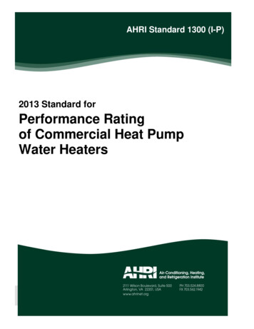
Design and Rating ofShell and Tube Heat Exchangers3. 0Design GuidelinesReferences: Hewitt et al “Process Heat Transfer” p267, Kern “Process Heat Transfer” Chapter 7,p127 and Perry Section11 p11-0 to p11-19DefinitionsHeat exchanger configurations are defined by the numbers and letters established by the Tubular ExchangerManufacturers Association (TEMA). Refer to Appendix V for full details.For example: A heat exchanger with a single pass shell and multi-pass tube is defined as a 1-2 unit. For a fixed tubesheet exchanger with removable channel and cover, bonnet type rear head, one-pass shell 591mm (231/4in) insidediameter with 4.9m(16ft) tubes is defined SIZE 23-192 TYPE AELTube DiameterThe most common sizes used are 3/4"od and 1"odUse smallest diameter for greater heat transfer area with a normal minimum of 3/4"od tube due tocleaning considerations and vibration.1/2"od tubes can be used on shorter tube lengths say 4ft.The wall thickness is defined by the Birmingham wire gage (BWG) details are given in Appendix XI(Kern Table 10)Tube Number and LengthSelect the number of tubes per tube side pass to give optimum velocity 3-5 ft/s (0.9-1.52 m/s) for liquidsand reasonable gas velocities are 50-100 ft/s(15-30 m/s)If the velocity cannot be achieved in a single pass consider increasing the number of passes.Tube length is determined by heat transfer required subject to plant layout and pressure drop constraints. To meet thedesign pressure drop constraints may require an increase in the number of tubes and/or a reduction in tube length.Long tube lengths with few tubes may give rise to shell side distribution problems.Tube Layout, Pitch and ClearanceDefinitions and NomenclatureBPTCdoDbaffle spacing(pitch)tube pitchclearancetube outside diametershell inside diameterPTCPTCSquare pitchTriangular pitchTube pitch is defined asPT do CSTAGGERED ARRAYINLINE ARRAYFLOWFLOWTriangular pattern provides a more robust tube sheet construction.Square pattern simplifies cleaning and has a lower shell side pressure drop.Typical dimensional arrangements are shown below, all dimensions in inches.Tube od (in)5/83/411 1 /411/2Square Pitch (in)7/8Note 11Note 21 1 /41 9/161 7 /8Triangular Pitch (in)25/32Note 115/16 or 1Note 121 1/41 9/161 7 /813Note 1 For shell 12” pitch(square) /1615Note 2 For shell 12” pitch(square) /16Table above uses minimum pitch 1.25 times tube diameter ie clearance of 0.25 times tube diameter.Smallest pitch in triangular 30º layout for turbulent / laminar flow in clean service.For 90º or 45º layout allow 6.4mm clearance for 3/4 tube for ease of cleaning.PAGE 8 OF 30MNL 032A Issued 29 August 08, Prepared by J.E.Edwards of P & I Design Ltd, Teesside, UKwww.pidesign.co.uk
Design and Rating ofShell and Tube Heat Exchangers3. 0Design GuidelinesShell DiameterThe design process is to fit the number of tubes into a suitable shell to achieve the desired shell side velocity4ft/s(1.219m/s) subject to pressure drop constraints. Most efficient conditions for heat transfer is to have the maximumnumber of tubes possible in the shell to maximise turbulence.Preferred tube length to shell diameter ratio is in the range 5 to 10.Tube count data are given in Perry Table 11-3 where the following criteria have been used1) Tubes have been eliminated to provide entrance area for a nozzle equal to 0.2 times shell diameter2) Tube layouts are symmetrical about both the horizontal and vertical axes533) Distance from tube od to centreline of pass partition 7.9mm( /16 ) for shell id 559mm (22in) and 9.5mm ( /8) forlarger shells.Heat Transfer AreaUsing the maximum number of tubes, subject to adequate provision for inlet nozzle, for a given shell size will ensureoptimum shell side heat transfer in minimizing tube bundle bypassing.The heat transfer area required design margin is then achieved by adjusting the tube length subject to economicconsiderations. On low cost tube materials it may be more economical to use standard lengths and accept the increaseddesign margin.It is a common practice to reduce the number of tubes to below the maximum allowed particularly with expensive tubematerial. In these situations the mechanical design must ensure suitable provision of rods, bar baffles, spacers, baffles tominimize bypassing and to ensure mechanical strength.Baffle Design - DefinitionsShellside cross flow area aS is given byWhereDBCPTas DC BPTshell i.d.baffle spacingclearance between tubestube pitchMinimum spacing (pitch)Segmental baffles normally should not be closer than 1/5th of shell diameter (ID) or 50.8mm(2in) whichever is greater.Maximum spacing (pitch)Spacing does not normally exceed the shell diameter.Tube support plate spacing determined by mechanical considerations e.g. strength and vibration.Maximum spacing is given by0.75B 74 doMost failures occur when unsupported tube length greater than 80% TEMA maximum due to designer trying to limit shellside pressure drop. Refer to attachments.Baffle cutBaffle cuts can vary between 15% and 45% and are expressed as ratio of segment opening height to shell insidediameter. The upper limit ensures every pair of baffles will support each tube.Kern shell side pressure drop correlations are based on 25% cut which is standard for liquid on shell side When steam orvapour is on the shell side 33% cut is usedBaffle pitch and not the baffle cut determines the effective velocity of the shell side fluid and hence has the greatestinfluence on shell side pressure drop.Horizontal shell side condensation require segmental baffles with cut to create side to side flowTo achieve good vapour distribution the vapour velocity should be as high as possible consistent with satisfying pressuredrop constraints and to space the baffles accordingly.Baffle clearancesThe edge distance between the outer tube limit (OTL) and the baffle diameter has to be sufficient to prevent tubebreakthrough due to vibration. For example fixed tube-sheet clearances are shown below.Refer to Perry p11-11 for floating head clearances.Shell inside diameter mm (in)Clearance shell id and OTL mm(in)7254(10) to610(24)11( /16)1 635(25)13( /2)PAGE 9 OF 30MNL 032A Issued 29 August 08, Prepared by J.E.Edwards of P & I Design Ltd, Teesside, UKwww.pidesign.co.uk
Design and Rating ofShell and Tube Heat Exchangers3. 0Design GuidelinesTube-sheet Layout (Tube Count)(Ref 4, page 577)Bundle diameter Db can be estimated using constants shown:Db do (N t K 1)1nWheretube o.d.number of tubesdoNtNumber PassesK1n10.3192.14220.2492.207Triangular Pitch pt 1.25 do460.1750.07432.2852.49980.03652.675Number PassesK1n10.2152.20720.1562.291Square Pitch pt 1.25 do460.1580.04022.2632.61780.03312.643Fouling ConsiderationsTypical fouling coefficients are shown in Appendix VII. It can be shown that the design margin achieved by applying thecombined fouling film coefficient is given by:Af UC1AChfwhere AC is the clean HTA , Af is the dirty or design HTA and UC is the clean OHTC.Fouling .0020.0010.001Results for Typical Fouling Coefficients (British Units)Fouling CoefficientsClean 500500250501000100050050Design Margin1.151.31.21.1Corrosion FoulingHeavy corrosion can dramatically reduce the thermal performance of the heat exchanger. Corrosion fouling is dependenton the material of construction selection and it should be possible to eliminate altogether with the right choice. However ifeconomics determine that some corrosion is acceptable and no data is available from past experience an allowance of1/16 in (1.59 mm) is commonly applied.Design MarginThe design margin to be applied to the design is based on the confidence level the designer has regarding the specificapplication and the future requirements for multipurpose applications. Design of condensers for multipurpose use, wherea wide possible variation in flow conditions can exist, provides a particular problem in this regard.It is standard practice to apply a design margin of 15% to the design (dirty) heat transfer area with the result that this isapplied to the design margin resulting from the application of the fouling film coefficients discussed previously giving anadded safety factor.Pressure Drop(8)For process design using a simulation the following preliminary conservative estimates are given for pressure drops dueto friction. Note an additional pressure change occurs if the exchanger is placed vertically.Initial Process Design Pressure Drop EstimatesProcess DescriptionPressure Drop (psi)Liquid streams with no phase change10Vapor streams with no phase change2Condensing streams2Boiling streams1PAGE 10 OF 30MNL 032A Issued 29 August 08, Prepared by J.E.Edwards of P & I Design Ltd, Teesside, UKPressure (kPa)7014147www.pidesign.co.uk
Design and Rating ofShell and Tube Heat ExchangersAPPENDIX IHEAT TRANSFER MODEL SYNOPSISShellside Film Coefficient Methods for Single Component Condensation in Laminar FlowHorizontal condenser subcoolers are less adaptable to rigorous calculation but give considerably higher overall cleancoefficients than vertical condenser subcoolers which have the advantage of well defined zones.The Nusselt Method (Hewitt et al p590)[C20]The mean heat transfer coefficient for horizontal condensation outside a single tube is given by the relationshipdeveloped by Nusselt. This correlation takes no account of the influence of vapour flow which, in addition to the effect ofvapour shear, acts to redistribute the condensate liquid within a tube bundle. k L3 ρL (ρL ρG )g λ ho 0.725 μ L do (Tsat Tw ) 0.25The Kern Method(Kern p263)[S2]Kern adapted the Nusselt equation to allow evaluation of fluid conditions at the film temperature k f3 ρf2 g λ 0.943ho μf do Δtf 0.25For horizontal tube surfaces from 0 to 180 the above equation can be further developed to give k f3 ρf2 g λ 0.725ho μf do Δtf 0.25McAdam extended the above equation to allow for condensate film and splashing affects where theloading per tube is taken to be inversely proportional to the number tubes to the power of 0.667. k f3ρf2 g 1.51 ho2 μf 0.33 4W 0.667 L Nt μf 0.33This equation requires the film to be in streamline flow corresponding to Reynolds Numbers in range 1800 to 2100The Eissenberg Method (Hewitt et al p660)[C20]Horizontal shell side condensation involving multiple tubes in the presence of vapour is much more complex than theNusselt single tube correlation, as the flow of condensate from one tube to another results in the condensate layerthickening on the lower tubes decreasing the heat transfer coefficient.For a bank of n tubes the heat transfer coefficient determined by the Nusselt Method above is modified by theEissenberg expression given below( 0.25hn ho 0.6 0.42 n) as compared with Kerns correctionhn ho n 0.167The Eissenberg correction is more conservative than that due to Kern with Nusselt method being the most conservativeie the highest film coefficient.Shellside Film Coefficient Methods for Single Component Condensation in Turbulent FlowMcNaught Method (Hewitt et al p661)[C21]This method is probably the best available at the moment as it takes into account the effects of shear controlled heattransfer and the combination of gravity and shear effects.PAGE 11 OF 30MNL 032A Issued 29 August 08, Prepared by J.E.Edwards of P & I Design Ltd, Teesside, UKwww.pidesign.co.uk
Design and Rating ofShell and Tube Heat ExchangersAPPENDIX IHEAT TRANSFER MODEL SYNOPSISTubeside Film Coefficient Methods for Single Component CondensationKern Modification of Nusselts equation (Perry 10-21, equation 10-105)Laminar FlowThis stratified flow model represents the limiting condition at low condensate and vapor ratesHorizontal condensation inside tubes based on do k L3 ρL (ρL ρG )g λ ho 0.815 π μL do (Tsat TW ) Based on tube length L this can be shown to be L k L3 ρL (ρL ρG )gho 0.761 WT μL 0.25 0.25Where WT is total vapor condensed in one tubeA simplification can be made by setting ρG 0 in the above correlations.The Nusselt Method (Hewitt et al p594)Chaddock and Chato adaptation for gravity stratifying flowFor horizontal condensation inside tubes there are two extreme cases1) Gravity controlled where the influence of vapour shear is low and we have a liquid film drainingunder gravity forming a stratified layer at the bottom of the tube2)Shear controlled where a uniform annular film is formed. The influence of gravity is negligiblecompared to the interfacial shear stress.For horizontal condensation under stratifying conditions (case 1) the mean coefficient for the whole circumference isgiven byho k L3 ρL (ρL ρG )g hLg μL do (Tsat TW ) 0.250.750.72 εG The Chemstations Method (Hewitt et al p580-p589 and Perry 10-21)[C23]Duckler (downflow) and Hewitt (upflow) adaptations to Deissler and von Karman equationsFor condensation under shear controlled conditions for vertical and horizontal conditions the methods for laminar andturbulent flow uses the following procedure for determining the heat transfer coefficient can be summarised :a) The interfacial shear stress is calculated.b) The condensate flow per unit periphery and the Reynolds Number for the liquid film Ref is calculated. c) Estimate δ which is a function of Ref andτδ which is a function of the liquid Prandtl Number PrLCpL (ρL τo )0.5e) Calculate the local liquid film heat transfer coefficient from the following relationshiphi τδAn alternative and more simple method due to Boyko and Kruzhilin is available but not used in CC-THERMBoyko and Kruzhilin adaptation of the Mikheev correlationVertical condensation inside tubes Mikheev correlationBoyko and Kruzhilin equationhLO 0.021kL(Re)0LO.8 (Pr )0L.43d ρL hi hLO 1 x 1 ρG 0.5where xPAGE 12 OF 30MNL 032A Issued 29 August 08, Prepared by J.E.Edwards of P & I Design Ltd, Teesside, UKis mean of end valueswww.pidesign.co.uk
Design and Rating ofShell and Tube Heat ExchangersAPPENDIX IHEAT TRANSFER MODEL SYNOPSISTubeside Film Coefficient Methods for Single Component CondensationVDI Film Method ( VDI Heat Atlas 1992 pJa6- pJa8) [C24]The Association of German Engineers (Verein Deutscher Ingenieure, VDI ) have developed extensive methods for heatexchanger sizing based on a Heat Atlas method.This method is available as an option in CC-THERM for condensation inside vertical tubes.Method for Multi-Component CondensationSilver Bell Ghaly (SBG) (Hewitt et al p635-p636 ) [C1] [C2]The SBG method is based on the following assumptionsVapor phase condensing / cooling follows the equilibrium integral condensation curve (i.e.,Tv TE )This condition is met provided the Lewis Number Le is close to unity, whereLe Sc PrAll the heat released, including that from the liquid phase passes from the interface to the coolantThe heat transfer dQ in an increment of exchanger area comprises heat extracted due to latent heat dQl and sensibleheat in the gas dQG and liquid dQL phases givingdQ dQl dQL dQG Ui (Ti TC ) dAThe flux of sensible heat from the vapor is given bydQG hG (TE Ti )dAdQG dAdQG dQ dAdQWe define a parameter Z whereZ Combining with the above we can showA QT0(1 Z Ui)hG dQU (TE TC )iDeviations from equilibrium will result in errors in the prediction of vapor temperature. If heat is extracted more rapidlythan equilibrium leads to the vapor temperature being less than TE the vapor is super cooled or saturated which canlead to fog formation leading to possible pollution problems. If heat is extracted more slowly than equilibrium giving avapor temperature greater than TE the vapor is superheated.PAGE 13 OF 30MNL 032A Issued 29 August 08, Prepared by J.E.Edwards of P & I Design Ltd, Teesside, UKwww.pidesign.co.uk
Design and Rating ofShell
Design and Rating of Shell and Tube Heat Exchangers PAGE 4 OF 30 MNL 032A Issued 29 August 08, Prepared by J.E.Edwards of P & I Design Ltd, Teesside, UK www.pidesign.co.uk 2. 0 Fundamentals The basic layout for a countercurrent shell and tube heat exchanger toget