Transcription
Virtual Allegiant Satellite ApplicationSFT-VASAenUser Manual
Virtual Allegiant Satellite ApplicationTable of Contents eniiiTable of Contents1Unpacking31.1Parts List32Product Description32.1Features32.2Recommended System Requirements43System Overview44Hardware Configuration54.1LTC 8780 Data Converter Unit54.2Configuring an Allegiant System for VASA Operation74.2.1Configuring the MCS for use with Digital Decoders74.2.2Configuring the MCS for use with Digital Encoders74.3Bosch Digital Decoders4.3.1Decoder Connections104.4Bosch Digital Encoders104.4.1Encoder Connections104.4.2Configuring an Encoder for PTZ Operation104.4.3Controlling PTZ Operation over a Network115VASA Installation125.1VASA README File125.2Security Device126VASA Configuration136.1Changing Login Password146.2Configuration Menu156.3Menu Commands156.3.1File Menu156.3.2View Menu166.3.3Options Menu166.3.4Help Menu167VASA Configuration Controls177.1Using the VASA Interface177.2Configuring the LTC 8780177.3Adding and Editing a Decoder187.4Adding and Editing an Encoder197.5Viewing VASA Log Events207.5.1Viewing the Log File207.5.2Using the VASA Event Log Window208Synchronizing VASA and MCS Configuration21Bosch Security Systems, Inc.9User ManualF01U074920 2.0 2007.09
iven Table of ContentsF01U074920 2.0 2007.09Virtual Allegiant Satellite ApplicationUser ManualBosch Security Systems, Inc.
VASA 1.201Unpacking en3UnpackingVerify that all parts shown in the Parts List have been included. If any items are missing, notifyyour Bosch Security Systems Sales or Customer Service Representative.1.1Parts ListQuantity11111ItemCD-ROM with SFT-VASA softwareSoftware security key (USB dongle)Software License AgreementVASA 1.20 User ManualRS-232 Interface Cable(Bosch Security Systems Part #S1385)2Product DescriptionThe Virtual Allegiant Satellite Application (VASA) is Bosch’s strategic product that allowsexisting Allegiant customers to transition gradually to pure IP technologies rather than a totaland instantaneous replacement.VASA reflects the reality that thousands of Allegiant users are satisfied and very comfortablewith their existing analog based matrix switcher and associated CCTV keyboards andmonitors. Security strategists also recognize that when the time comes for camera expansion,that IP network-based technologies offer unique benefits, such as simplified cabling: A singleCAT-5 cable can carry hundreds of video, audio, Pan/Tilt/Zoom (PTZ) control, serial ports,alarm inputs, and relay output lines.VASA acts as the integration bridge between an existing Allegiant and the new digital basedCCTV system (the ‘satellite’) that uses Bosch digital video encoders and decoders. With VASA,the new IP technology is transparent to the existing Allegiant users who continue to use theirIntuikey CCTV keyboards for switching and PTZ control of video on classic analog monitors.VASA replaces dedicated analog trunk lines and in addition to remote PTZ functionality, itsupports encoder relay activations.VASA supports the Allegiant LTC 8100 through LTC 8900 Series matrix switchers. In additionto PTZ control, VASA provides auxiliary and preposition control of the IP-based cameras.Because VASA fully integrates the Allegiant with Bosch video IP products, the Allegiantmonitor displays remote camera titles.2.1Features–Integrates Allegiant with network IP CCTV–Allows users to control IP cameras via the IntuiKey keyboard–Allows analog monitors to display images from remote systems via an IP network–Controls PTZ and auxiliary and preposition settingsThe VASA 1.20 software supports:––1,024 Encoders and 32 DecodersBosch devices with internal encoders, such as the AutoDome Modular Camera Systemwith IP module (VG4 Series), the Dinion IP cameras, and the FlexiDome IP cameras.–Bosch Security Systems, Inc.Allegiant LTC 8100-8900 Series Matrix SwitchersUser ManualF01U074920 2.0 2007.09
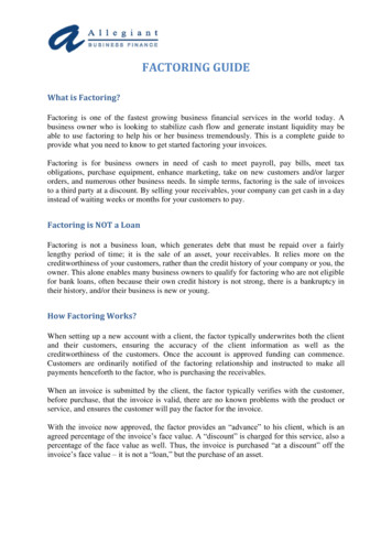
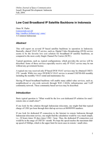
42.23en System OverviewVASA 1.20Recommended System Requirements–Microsoft Windows compatible PC Platform–Windows 2000 (Service Pack 3 or later), or Windows XP Professional–Intel Pentium 2.8 GHz or greater–512 Mb RAM–50 Mb fixed drive space–CD-ROM drive–10/100 Base-T ethernet interface–1 USB port (or USB hub port) for USB security dongle–One (1) serial port for external interface communications–Additional serial ports required if multiple interfaces are used–SVGA Display or compatible video cardSystem OverviewVASA is a PC application that allows commands generated from an Allegiant LTC 8780Satellite Address Decoder to control a network digital video system.Figure 3.1 depicts the components of a VASA system:–Allegiant Matrix Switcher (LTC 8100 Series through LTC 8900 Series)–Bosch cameras with encoders (VG4 AutoDome IP, Dinion IP, and FlexiDome IP)–Cameras, monitors and Allegiant keyboards–LTC 8780 Satellite Address Decoder–Bosch Digital Video Encoder–Bosch Digital Video Decoder–PC station running VASA softwareFigure 3.1 Virtual Allegiant Satellite Application SystemF01U074920 2.0 2007.09User ManualBosch Security Systems, Inc.
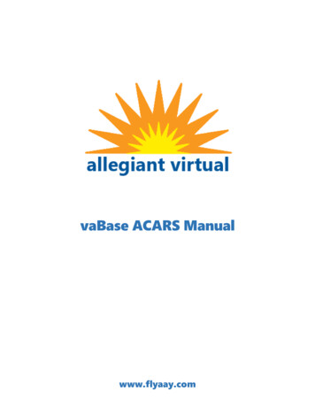
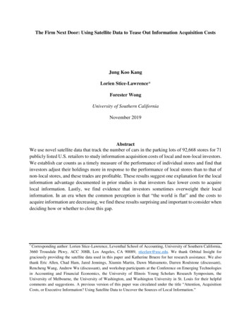
VASA 1.20Hardware Configuration en45Hardware ConfigurationVASA is designed to work with an Allegiant Matrix/Controller setup in a satellite configuration.It requires an Allegiant Matrix/Switcher, an LTC 8780 Data Converter Unit, Bosch DigitalDecoders and Encoders, and a PC work station. In large systems, an LTC 8568 SignalDistribution Unit can be used for multiple satellite systems. Once VASA is configured, nofurther user interaction is required.The LTC 8786 RS-232 to Biphase converter can also be used to convert receiver/driver andAutoDome RS-232 control code protocol into Allegiant biphase control code for operatingAutoDome cameras.You should be familiar with the Allegiant Matrix Switch control system, Windows-basedsoftware, and have a general knowledge of networking.Refer to the Allegiant Instruction Manual for setting up an Allegiant Satellite System, which canbe found on the Bosch website: www.boschsecurity.com.4.1LTC 8780 Data Converter UnitThe LTC 8780 Data Converter is required to convert Allegiant Satellite commands into aformat used by VASA.iNOTICE! The CCL Address Selected number must match the Allegiant MCS Bay number.1.Connect the LTC 8780 CODE IN connector to the biphase port of the Allegiant MasterSystem.Refer to the LTC 8780 manual for Biphase connections, located on the Bosch website atwww.boschsecurity.com.2.Connect the LTC 8780 to the PC COM port using the Bosch S1385 RS-232 InterfaceCable, or a fully wired equivalent, null-modem RS-232 data cable.The figure belowdepicts this connection.CDRx(Side View)59423871GndDSR6(Front View)9-pin FemaleFigure CTS(Side View)594382716(Front View)9-pin FemaleIndustry Standard Null-modem Cable (Bosch Part Number S1385)The following two tables summarize the dip switch settings for the LTC 8780 (Table 4.1) andthe selected CCL address (Table 4.2).Bosch Security Systems, Inc.User ManualF01U074920 2.0 2007.09
6en Hardware ConfigurationVASA 1.20Dip Switch Switch NumberRecommended FunctionS101SettingONON1 (BAUD)2 (BAUD)S1033 (CODE DIST)4 (ADDR FUNCT)1 (RCVR DRVR)2 (XPOINT)3 (CCL)4 (MATCH)1–4 (ADDR LOW)S1041–4 (ADDR HIGH)S1051 (MODEM CMD)2 (ORIGINATE)3 (CHECK CTS)4S102Table 4.1RS-232 Baud Rate of 38,400 bpsOFFOFFONOFFONONBiphase input to Biphase outputCCL Address SelectEnable transmission of R/D messagesDisable transmission Crosspoint messagesEnable transmission of CCL messagesCCL message address checkedAddress or block select low order bits (mustbe set to Satellite Address)Address or block select high order bits (mustbe set to Satellite Address)Not applicableModem command ATACheck CTS before transmitting dataNot usedOFFOFFONOFFLTC 8780 Dip Switch SettingsAddress DIP OFFOFFONONXONONOFFONOFFONOFFONOFFONXOFFONTable 4.2F01U074920 2.0 2007.09CCL AddressS103Selected (MCSBay Number)12345678(continue series)255256CCL Address SelectUser ManualBosch Security Systems, Inc.
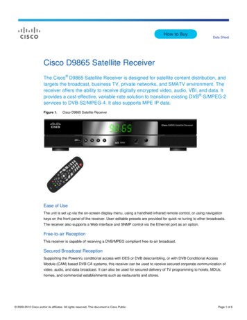
VASA 1.204.2Hardware Configuration en7Configuring an Allegiant System for VASA OperationThe following section details the steps necessary to configure the Allegiant Master ControlSoftware (MCS) for use with the Bosch Digital Decoders and Encoders.4.2.1Configuring the MCS for use with Digital DecodersConfigure the MCS camera table as you would a typical Allegiant Satellite system.1.Determine the Input to serve as an Allegiant Satellite trunk for the decoder. Then selectTrunk from the Installation column.2.Set the Bay Number of the Trunk to match the LTC 8780 CCL Address Selected that isconnected to VASA.3.Set a unique Monitor Number for each trunkline. This number is used to setup the BoschDecoder as detailed later. Note the relationship between the Satellite Trunk Monitor inthe decoder and the Monitor Number in the MCS.Figure 4.24.4.2.2Relationship between the MCS and the DecoderRepeat the steps above for each decoder trunk.Configuring the MCS for use with Digital EncodersConfigure the Allegiant MCS Camera Table as follows:1.Determine the Input to serve as a remote camera. Then set a unique number for eachcamera under the Camera Number column. This number is used to setup the BoschEncoder as detailed later.The relationship between the Encoder settings and the Allegiant MCS depends if you usea logical camera address (as depicted in Figure 4.3 below) or if you use a physical cameraaddress (as depicted in Figure 4.4 below).Bosch Security Systems, Inc.User ManualF01U074920 2.0 2007.09
8en Hardware ConfigurationiVASA 1.20NOTICE! To use the Allegiant physical address option, the Allegiant CPU must be configuredto use the physical camera number. From the MCS menu select Parameter Options UsePhysical Camera Number for OSRD. Be sure to download the MCS changes to the AllegiantCPU after modifications are made.Figure 4.3 Relationship using the Allegiant Logical Camera Address OptionF01U074920 2.0 2007.09User ManualBosch Security Systems, Inc.
VASA 1.20Hardware Configuration enFigure 4.49Relationship using the Allegiant Physical Camera Address Option2.Enter a Camera Title.3.Set the Installation type to Remote With Local Overlay.4.Set the Bay Number of the Trunk to match the LTC 8780 CCL Address Selected that is5.Repeat the above steps for each encoder.connected to VASA.4.3Bosch Digital DecodersThe number of Bosch digital decoders (trunk lines) required in a system depends on thenumber of monitors used simultaneously to view the video from the digital system.Figure 4.5 Decoder Configuration for Video OutputBosch Security Systems, Inc.User ManualF01U074920 2.0 2007.09
10en Hardware Configurationi4.3.1VASA 1.20NOTICE! The decoder must be configured for the appropriate video format, PAL or NTSC.Decoder ConnectionsConnect the VIDEO output of the decoder to the VIDEO input of the Allegiant-based system onthe Trunk number programmed in the MCS Camera Table.4.4Bosch Digital EncodersThe number of Bosch digital encoders required in a system depends on the number ofcameras connected to the encoders.Bosch Encoders provide relay output(s) that are controlled by AUX ON/OFF commandsstarting serially at 201. The fist relay ON device is enabled using the AUX ON 201 commandand disabled using the AUX OFF 201 command. The second relay ON device is enabled usingthe AUX ON 202 command and disabled using the AUX OFF 202 command.4.4.1Encoder ConnectionsConnect the VIDEO output of the camera to the VIDEO input of the encoder.iNOTICE! You must make these connections for a VG4 Series AutoDome camera without an IPmodule. These connections, however, are not necessary for a VG4 Series AutoDome camerawith an IP module.The following table summarizes the connections between a Bosch Digital Encoder and anAutoDome, an Allegiant Code Converter, or an Allegiant Receiver/Driver.Bosch DigitalAutoDomeEncoder(ver. 5.0, G3, or(ver. 3.0, 4.0,(9-pin connector)higher)G3, and VG4)2 RXD3 TXD5 GNDRS-232 ModeTXDRXDGNDRS-232 ModeRXDTXDGNDTable 4.31AutoDomeAutoDomeAllegiant CodeRS-485 Mode1 Converters andReceiver/DriversRXD (Data )TXD (Data )GNDRS-232 ModeTXDRXDGNDEncoder Pin Connections for PTZUse COM1 (RS422/485) port on the Video Digital Encoder and set the AutoDome internalslide switch to the ON position for RS-485.4.4.2Configuring an Encoder for PTZ OperationUsing a Windows-based browser, such as Microsoft Internet Explorer, enter the IP address orthe DNS name of the encoder that you need to configure. From the encoder web page, pressthe Expert Mode button or Settings link and then configure the encoder settings for RS-232 asillustrated in Figure 4.6 below.iNOTICE! You must configure the PTZ operation for a VG4 Series AutoDome with an IP module.For more information, refer to the Online Help on the Settings page of the VG4 AutoDomeconfiguration Web page.F01U074920 2.0 2007.09User ManualBosch Security Systems, Inc.
VASA 1.20Hardware Configuration enFigure 4.611Encoder Configuration for RS-232 ConnectionThe interface settings for COM1 are as follows:i4.4.3–Set the Serial port function to Transparent.–Set the Baud Rate to 9600.–Accept the default value of 8 for data bits.–Set Stop Bits to 1.–Set Interface Mode to RS-232.–Set Half-duplex Mode to OFF.NOTICE! The AutoDome or the PTZ device Biphase address must be set to 0000 or to the PTZcamera address entered in the Add/Edit Encoder dialog box. SeeControlling PTZ Operation over a NetworkCertain devices that control PTZ operation over a VASA network have the following actions:–When a VIDOS PC operator is in control of a PTZ-enabled camera on the network, there isa 10-second hold from the last command before releasing the camera to an AllegiantSystem command. (VIDOS is an optional PC software package used to control Boschnetwork-based products.)–When an Allegiant System operator is in control of a PTZ-enabled camera, there is a foursecond hold from the last command before releasing the camera to another user.Bosch Security Systems, Inc.User ManualF01U074920 2.0 2007.09
125en VASA InstallationVASA 1.20VASA InstallationInsert the CD and wait for the installation program to open the dialog box. If the installationprogram does not open the dialog box, browse through the CD and run Setup.exe. From thedialog box, click the VASA Install button. The Installation Wizard guides you through the entireprocess.5.1VASA README FileOccasionally, revisions are made to the VASA software that are not reflected in this manual.These changes are described in the VASA README file. Read this file whenever a new versionof VASA is installed. There is an icon for the README file in the VASA start menu group.5.2Security DeviceBefore the program runs on the host computer, the hardware security key must be connectedto an available USB port on the computer. If necessary, locate this port with the help of thehardware manual that comes with the host computer. Push the security key into place. Thesecurity key LED lights if it is installed correctly.F01U074920 2.0 2007.09User ManualBosch Security Systems, Inc.
VASA 1.206VASA Configuration en13VASA ConfigurationThe installation procedure creates a Start Menu icon. Double click this icon to run thesoftware. The program opens and displays the VASA Login dialog box.Figure 6.1VASA Login dialog boxIf this is the first time the program is being run, select Installer when prompted for ausername. The default password for the Installer is the number 1.By default, the VASA software utilizes three privilege levels:Privilege Level Password AccessInstaller:1Has access to all program features.Administrator: 2Has access to all program features but not to all User ProfileOperator:3settings.Has limited access to features.Installers and Administrators can utilize the User Profile dialog box option in the File menu todelete a user or to add a user name to the login list.Figure 6.2User Profile Dialog BoxEach user can be assigned to one of the following user levels: installer, administrator, oroperator. Installers can also assign the privilege of Installer to other users. See Table 6.1 for alist of user privileges. Administrators can alter all entries except those of an installer.Bosch Security Systems, Inc.User ManualF01U074920 2.0 2007.09
14en VASA ConfigurationVASA 1.20User ActionInstaller Administrator OperatorOpen VASA file Create New VASA file Save VASA file Print Configure LTC 8780 settings Select log file Enable log to file Set log level high Launch log viewer Auto-login Add decoder Delete decoder Edit decoder Browse to decoder Add encoder Delete encoder Edit encoder Browse to encoder Clear log Shutdown VASA Table 6.16.1User PrivilegesChanging Login PasswordTo change the login password to prevent unwanted user access, select the File menu andchoose User Profile to access the VASA User dialog box. Then, click the Modify User button toopen the User Properties dialog box.Figure 6.3 User Properties Dialog BoxF01U074920 2.0 2007.09User ManualBosch Security Systems, Inc.
VASA 1.206.2VASA Configuration en15Configuration MenuFor first time setup, the software opens a new VASA Configuration window.Figure 6.4VASA Configuration WindowOnce you configure the settings, you can save the configuration by selecting the File menu andchoosing Save. Multiple configuration files can also be created and saved by selecting the Filemenu and choosing Save As; then by typing a unique file name.VASA loads the last saved configuration file automatically. If a different configuration file isdesired, select the File menu and choose Open to find a previously saved configuration file. AVASA configuration file has a .vas extension.6.3Menu CommandsSome VASA menus include a toolbar button. Clicking the toolbar button is equivalent toselecting the corresponding menu item. The following sections describe the VASA menus.6.3.1File MenuItemNewOpenSaveSave AsLog InBosch Security Systems, Inc.DescriptionCreates a new VASA configuration file.Opens an existing VASA configuration file.Saves an opened VASA configuration using the current file name.Saves and opened VASA configuration to a specified file name.Allows a new user to log in.User ManualF01U074920 2.0 2007.09
16en VASA ConfigurationItemUser ProfileVASA 1.20DescriptionDisplays the user profile dialog box from which user information(names, passwords, and group memberships) can be managed. Inaddition, users can be added, modified, or deleted, and passwordschanged.PrintPrints a document.Print SetupSelects a printer and a printer connection.(recent opened file list) Lists the names of the four most recently used files. Select one ofExit6.3.2View MenuItemToolbarStatus Bar6.3.3these names to open the associated file.Exits VASA.DescriptionShows or hides the toolbar.Shows or hides the status bar.Options MenuItemLTC 870 SettingsDescriptionDisplays the dialog box from which the user sets the COM port, bitsSelect Log FileLog File EnabledLog Level - High DetailLog ViewerAuto Loginper second, flow control, and PTZ commands.Accesses the Open dialog box from which a user selects a log file.Enables the log file. Default is set to On.Toggles high detail or normal detail logging. Default is set to Off.Displays the current log file.VASA automatically logs in as Operator with the default password(the number 3) on the next startup.6.3.4Help MenuItemVASA HelpAbout VASADescriptionDisplays the VASA Help System.Displays the VASA software copyright and version numberinformation.F01U074920 2.0 2007.09User ManualBosch Security Systems, Inc.
VASA 1.20VASA Configuration Controls en717VASA Configuration ControlsThis section provides procedures for using the VASA interface, configuring parameters, andfor adding or editing an encoder and a decoder.7.1Using the VASA Interfacei1.Click the Add button to open the Add dialog box and to enter a new item to the list.2.Click the Delete button to delete the selected item in the list.3.Click the Edit button to open the Edit dialog box and to edit the selected item.NOTICE! The Browse button opens the web browser on the PC and connects to the selectedencoder/decoder’s web page. The PC may require software to be installed or updated beforethe web browser can properly display the encoder/decoder video. Refer to the CD suppliedwith the Bosch Digital encoder/decoder for the necessary software.4.Click the Browse button to access the web page for the selected encoder/decoder whereyou can check and update configuration information and to check the status of theencoder/decoder.7.25.Click the Detail check box to view diagnostic details in the Event Log window.6.Click the Clear button to delete all messages in the Event Log window.Configuring the LTC 8780This dialog box allows configuration of the communication between the PC and LTC 8780Code Converter. From the main screen, select the Options menu and choose LTC 8780Settings.Figure 7.1LTC 8780 SettingsMake the following settings:Port SettingActionCOM PortSelect the PC COM port connected to the LTC 8780. The default value isCOM1.Bits per SecondSelect a standard PC COM port rate. The default value is 38,400 bps.Flow ControlAccept the default value of Hardware.Translate Repetitive Check the box to translate repetitive PTZ commands to non-repetitivePTZ CommandsBosch Security Systems, Inc.commands to reduce network bandwidth.User ManualF01U074920 2.0 2007.09
187.3en VASA Configuration ControlsVASA 1.20Adding and Editing a Decoder1.Click the Add or the Edit button, located to the right of the Decoder Configuration box.VASA opens the Add or Edit Decoder dialog box.Figure 7.2 Add/Edit Decoder Dialog Box2.Set the following parameters:a.Type a valid number for the Satellite Trunk Monitor. Refer to Figure 4.2, on pagepage 7, for an illustration of obtaining a valid number from the Allegiant MCS Table.Note that this Satellite Trunk Monitor number must be unique and must be between1 and 999.b.Type the IP address or the name for the decoder.c.Select one of the following decoder models from the drop-down box:VideoJet 10E, VIP 10E, VIP 1000E, or VIP XD, XDA.3.d.Select either Service or User from the Username drop-down box.e.Type the password associated with the Username.Click OK to accept the specified value.–If a data value is invalid, VASA displays an error message that indicates a specificerror and lists an acceptable data range (if applicable). If multiple data errors exist,VASA displays one error message at a time until you correct all errors or cancel.–F01U074920 2.0 2007.09Click Cancel to exit the dialog box without making any changes.User ManualBosch Security Systems, Inc.
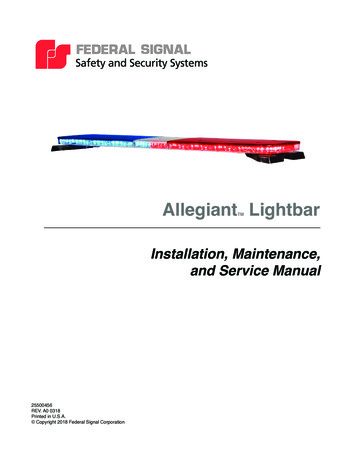
VASA 1.207.4VASA Configuration Controls en19Adding and Editing an Encoder1.Click the Add or the Edit button, located to the right of the Encoder Configuration box.VASA opens the Add or Edit Encoder dialog box.Figure 7.32.Add/Edit Encoder dialog boxSet the following parameters:a.Type a valid value for the Logical Camera Number. Refer to Figure 4.3, on page 8,and to Figure 4.4, on page 9, for an illustration of obtaining a valid number from theAllegiant MCS Table.Note that this Logical Camera Number must be unique and must be between 1 and9,999.b.Type the IP address or the name for the encoder. You can enter a duplicate IPaddress or name because certain encoders send images from multiple cameras overthe same IP address.c.Select one of the following encoder models from the drop-down box:VideoJet 10S; VIP 10S; VIP X1, X1A, X1P and X1AP; VIP X2 and X2A; VideoJet 8000/XPro V8; VideoJet 8004/XPro V8-X4; VideoJet 8008/XPro V8-X8; VIP 1000S; VIPX1600; Dinion IP (LTC 0455 and LTC 0495); AutoDome IP (VG4 Series); FlexiDomeIP; VideoJet X10; VideoJet X20; and VideoJet X40.Note that certain encoders support multiple cameras over the same IP address.d.Select Service, User, or Live from the Username drop-down list.e.Type the password associated with the Username.f.Select a value from the Video Input Channel drop-down box. If this video is the firstyou input, accept the default value of 1. If you enter a duplicate IP address, the VideoInput Channel drop-down list displays values 1 to 8, inclusive.If you enter a duplicate IP address for the encoder (in step 2b), VASA copies theencoder settings for the previous entry of the IP address and displays the followingwarning message:Figure 7.4Warning Message3.Click Yes to continue.4.Select a value from the Video Format drop-down list.Bosch Security Systems, Inc.User ManualF01U074920 2.0 2007.09
20en VASA Configuration Controls5.VASA 1.20Select COM1 or COM2 from the Encoder Port for PTZ Data drop-down list to specify theencoder COM port that is connected to a PTZ camera.–Select COM1 if the encoder connects to the PTZ camera via RS-422/485/232.–Select COM2 if the encoder connect to the PTZ camera via RS-232 only. Thisselection may not be applicable for all models.6.Type the appropriate camera address for the PTZ Camera Address.7.Click OK to accept the specified values. Repeat this procedure to configure otherencoder channels.Click Cancel to exit the dialog box without making any changes.7.5Viewing VASA Log EventsVASA is capable of recording system errors, warnings, and diagnostic messages to a file on thePC. In addition, VASA can record additional diagnostic events intended for troubleshooting.VASA offers two methods to view the contents of the log file, either through the WindowsNotepad application or in real time from the VASA Event Log window.7.5.1Viewing the Log FileTo view the contents of the log file, select the Options menu and choose Log Viewer. VASA,then opens the Windows Notepad application to display the contents of the log file. From thiswindow you can scroll through past events and print the entire log file.7.5.2Using the VASA Event Log WindowThe VASA Event Log displays the errors, warnings, and messages written to the log file, withthe most recent messages displayed at the top of the Event Log.To use the Event Log:1.Select the Options menu and choose the Log to File Enabled option.VASA now writes all system errors, warnings, and diagnostic messages to the log file.2.To record more detailed information, select the Options menu and choose the Log Level High Detail option.3.To view the log file,4.To view detailed diagnostic events, click the Detail button.5.To clear the messages from the Event Log window, click Clear. VASA displays a warningmessage.Note that this action clears the messages only in the Event Log window. The messagesare preserved in the actual log file.Figure 7.5 Event Log Display Message6.F01U074920 2.0 2007.09Click OK to clear all the messages from the Event Log.User ManualBosch Security Systems, Inc.
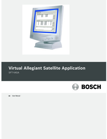
VASA 1.208Synchronizing VASA and MCS Configuration en21Synchronizing VASA and MCS ConfigurationThe figure below illustrates the synchronized relationship between the settings of theAllegiant Master Control Software (MCS) and the VASA software.Bosch Security Systems, Inc.User ManualF01U074920 2.0 2007.09
22en Synchronizing VASA and MCS ConfigurationF01U074920 2.0 2007.09VASA 1.20User ManualBosch Security Systems, Inc.
Bosch Security Systems, Inc.130 Perinton ParkwayFairport, New York, 14450USATelephone 1 (585) 223 4060 1 (800) 289 0096www.bosch-securitysystems.com Bosch Security Systems, Inc., 2007; F01U074920 2.0 2007.09; Data subject to change without notice.
Refer to the Allegiant Instruction Manual for setting up an Allegiant Satellite System, which can be found on the Bosch website: www.boschsecurity.com. 4.1 LTC 8780 Data Converter Unit The LTC 8780 Data Converter is r