Transcription
National Aeronautics and Space AdministrationOrbitalDebrisQuarterly NewsVolume 18, Issue 2April 2014International Space StationManeuvers Twice to Avoid Tracked DebrisInside.Nicholas JohnsonRetires as NASA ChiefScientist for OD2First Results ofWFPC2 CraterAnalysis Presentedat 2014 LPSC2NASA MCAT'sNew Destination isAscension Island4Hypervelocity ImpactTest with Large MassProjectile6Space Missionsand SatelliteBox ScoreA publication ofthe NASA OrbitalDebris Program OfficeAfter more than a year without a collisionavoidance maneuver, the International Space Station(ISS) recently performed two maneuvers to avoidconjunctions with two separate debris pieces. The firstmaneuver was implemented at 1:30 GMT on 17 Marchagainst tracked debris (International Designator1979-095BJ, U.S. Space Surveillance Network [SSN]satellite number 36917). This was the 17th ISS collisionavoidance maneuver since 1999, but the first since31 October 2012. The debris was a small, high dragobject that originated from the Meteor 2-5 spacecraft(International Designator 1979-095A, U.S. SSNnumber 11605). Meteor 2-5 was a Soviet meteorological satellite that was launched into an 880 km x865 km, 81.2 inclination orbit on 31 October 1979.The satellite has experienced multiple debris releaseevents since that time, and 36917 was one of thosecatalogued by the U.S. Space Surveillance Network.The second maneuver (18th in ISS history)occurred on 3 April at 20:42 GMT. The predictedconjunction was against mission-related debrisfrom an Ariane 5 launch (International Designator2009-044D, U.S. SSN number 35758). The debris wasa SYLDA (SYstème de Lancement Double Ariane)used to launch two satellites on an Ariane 5. Thisobject was in a highly elliptical orbit (25,842 x 295 km)with an inclination of 2.5 and had a drag eight timesgreater than the ISS. Due to the high eccentricity anddrag of the object, unusually large uncertainties wereassociated with its trajectory prediction. Although thefinal update prior to the maneuver indicated one wasnot needed, with the fluctuations in the SYLDA’s orbit,a decision was made to perform the maneuver. NASA Resumes Haystack Data Collection9After more than a 3-year gap in coverage,the MIT Lincoln Laboratory Haystack radar hasresumed collecting debris data for the NASAOrbital Debris Program Office (ODPO). TheHaystack collects data on objects as small as5 mm in the low Earth orbit (LEO) region. Theradar’s new name, reflecting its new capabilities,is the Haystack Ultra-wideband Satellite ImagingRadar (HUSIR). The ODPO mission does notuse wide-band, and will continue to use an X-bandcontinuous waveform, most often staring at 90 azimuth and 75 elevation. Approximately onethird of the time, the radar will stare at a southazimuth to collect data on debris with lowerinclination orbits. Debris objects passing throughRadome cap lift in May 2010 was one of the first steps inthe HUSIR integration sequence. The HUSIR has increasedW-band resolution while maintaining X-band sensitivity.continued on page 2
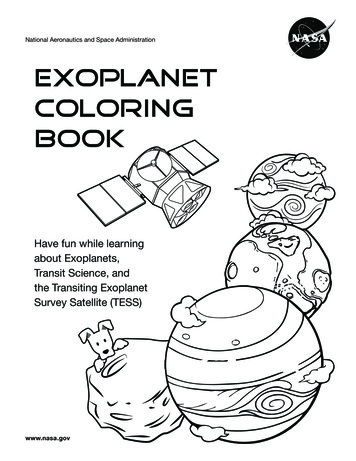
Orbital Debris Quarterly NewsHaystack Datacontinued from page 1the beam are recorded when the signal-tonoise ratio (SNR) rises above a threshold. SeeODQN, October 2013, p. 4 for more detailson how the ODPO uses the data.During the down period, the HaystackAuxiliary Radar (HAX) collected additionalhours of data to compensate for the loss ofHaystack data. With its wider beam, HAXis useful in detecting larger, but still small,objects (approximately 2 cm and larger objectsin LEO). However, HAX cannot substitutefor the sensitivity of the larger radar, and it isgood to have Haystack, now HUSIR, back infull operation. Nicholas Johnson Retires as NASA Chief Scientist for Orbital DebrisMr. Nicholas Johnson, NASA ChiefScientist for Orbital Debris since 1996, retiredon March 28 after 43 years of governmentservice and more than 35 years of workingorbital debris issues. As Chief Scientist,Mr. Johnson served as the agency authorityfor orbital debris, including all aspects ofenvironment definition, present and future,and the operational and design implications ofthe environment to both manned and roboticspace vehicles operating in Earth orbit. He wasresponsible for conceiving, conducting, anddirecting research to define the orbital debrisenvironment, for determining operationaltechniques for spacecraft to protect themselvesfrom the environment, and for recommendingtechniques to minimize the growth in thefuture orbital debris environment.During his career, Mr. Johnson servedin the Air Force as an aviation electronicstechnician and had one tour of duty inVietnam. Later, as an officer in the U.S. Navy,Mr. Johnson was an instructor and served asDirector of the Heat Transfer and Fluid FlowDivision at the Navy’s Nuclear Power School.Mr. Johnson worked in industry from1979 to 1996, first at Teledyne BrownEngineering and later at Kaman Sciences. Hebecame an expert on space surveillance and theSoviet space program. He also worked on theStrategic Defense Initiative and the F-15 AntiSatellite (ASAT) missile program. From theseexperiences, he became a strong advocate forlimiting the growth of orbital debris.After joining NASA, Mr. Johnson workeddiligently to broaden and strengthen orbitaldebris mitigation guidelines and standardswithin NASA, the U.S. Government, andinternationally. Due largely to Mr. Johnson’sdiligence, the U.S. Government Orbital DebrisMitigation Standard Practices were approvedin 2001 and the Space Debris MitigationGuidelines of the Committee on the PeacefulUses of Outer Space (COPUOS) were adoptedfirst by COPUOS and later by the full UnitedNations in 2007. Mr. Johnson led the U.S.delegation to the Inter-Agency Space DebrisCoordination Committee (IADC) from 1996to 2013.Mr. Johnson is the author of severalbooks including Artificial Space Debris withDarren McKnight and books on the Sovietspace program. He has received many awardsincluding the NASA Distinguished ServiceMedal, the NASA Exceptional AchievementMedal, and the Department of Defense’s JointMeritorious Civilian Service Award.Mr. Johnson’s many technical accomplishments and his ability to simultaneously bridgecultural and technical divides will be sorelymissed. First Results of WFPC2 Crater Residue AnalysisPresented at the 2014 LPSCThe annual Lunar and Planetary ScienceConference (LPSC) brings together the world’sexperts in the planetary sciences, astronomy,geophysics, geochemistry, and geology topresent their latest research results. The 45thLPSC was held 17-21 March 2014 at TheWoodlands, Texas. Five posters describingthe research and analysis efforts of theinternational NASA-European Space Agencyteam examining the Hubble Space Telescope2(HST) Wide Field Planetary Camera 2 (WFPC2)impact features and crater residues (Figure 1)were presented at Tuesday evening’s Presolar,Interplanetary and Cometary Dust session. Theposters, all bearing the titular prefix “Impactson the Hubble Space Telescope Wide Field andPlanetary Camera 2”, examined Microanalysisand Recognition of Micrometeoroid Compositions (Kearsley et al., abstract #1733), IonBeam Analysis of Subtle Impact Features(Colaux et al., #1727), Smaller Particle Impacts(Ross et al., #1514), Larger Particles (Kearsleyet al., #1722), and Experimental Simulation ofMicrometeoroid Capture (Price et al., #1466).Kearsley et al. (#1733) describes thedevelopment of scanning electron microscope(SEM) energy dispersive X-ray (EDX) analysistechniques and protocols required to categorizeimpact crater residues as being of orbitalcontinued on page 3
www.orbitaldebris.jsc.nasa.govWFPC2 Cratercontinued from page 2debris, micrometeoritic (MM), or unknownorigins, though this poster, like all five,concentrates on the MM component. Despitethe complex nature of the WFPC2 surface,carefully calibrated EDX spectra allow theteam to ascertain the compositional signaturesof impactors. Colaux et al. describe techniquesdeveloped at the University of Surrey’s IonBeam Centre, using ion beam analysis, toassess residue constituents for those cratersfound particularly challenging to SEM-EDXanalysis. Proton-Induced X-ray Emission(PIXE) has demonstrated its superior abilityto find and assess the signatures for very lowconcentration impact residues. The majorityof impact features observed were small, notpenetrating the WFPC2 thermal paint layer,and Ross, et al. discusses the recognition,analysis, and interpretation of residues foundin these smaller features. About 90% of thesecontained hypervelocity impact melt features,thus preserving information regarding theimpactor’s elemental constituents and origins.Figure 2 depicts one such crater and itselemental enrichment compared to the surfacebaseline composition; this crater displayed anexcess of magnesium (Mg) and iron (Fe) butnot aluminum (Al), leading to the conclusionthat the trace element features are derived fromthe impactor and not the WFPC2 Al substrate.Kearsley et al. (#1722) describes the analysis of63 larger impact features ( 700 µm size) andtheir residue materials. Price, et al. describesteam efforts to simulate the impact of silicateand sulfide minerals on WFPC2 analogues.Although conducted at lower velocities thanexpected for MM in LEO, the impact featuresand residue compositions closely matchWFPC2 features. Their results validate theanalytical methods presented in other postersfor trace residue identification.Taken as an ensemble, these postersrepresent the first presentation of the extensiveanalytical results generated by the internationalteam’s comprehensive analyses of the WFPC2impact features. The reader is directed tothe Universities Space Research Association’swebsite, 611.pdf, for electronicaccess to these posters. WFPC2Radiator shield2 mm2 mm2 mmFigure 1. (Top) STS-125 astronaut stows WFPC2 after removing it from theHST. (Bottom) diverse features sizes in larger cores collected by NASA ODPO.Figure 2: (Top) Elemental mapping for Mg, silicon (Si), and zinc (Zn) – thelatter dominated by the thermal paint. (Bottom) SEM-EDX energy peaks,background or baseline in blue, excess due to residue in red.UPDATEYOUR SUBSCRIPTION ADDRESS. If you have stopped receivingemail notification when the latest ODQN is available, please update your email address using theODQN Subscription Request Form located on the NASA Orbital Debris Program Office website,www.orbitaldebris.jsc.nasa.gov. This form can be accessed by clicking on “Quarterly News” in the Quick Links area ofthe website and selecting “ODQN Subscription” from the pop-up box that appears.3
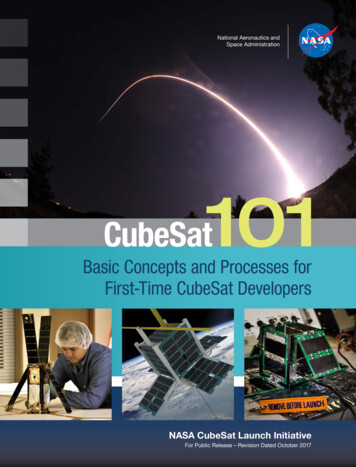
Orbital Debris Quarterly NewsPROJECT REVIEWThe NASA Meter Class Autonomous Telescope'sNew Destination is Ascension IslandS. LEDERERThe Meter Class Autonomous Telescope(MCAT) will be the newest optical sensordedicated to NASA’s mission to characterize thespace debris environment. It is the successorto a series of optical telescopes developed andoperated by the NASA Orbital Debris ProgramOffice (ODPO) to monitor and assess thedebris environment in (1) low Earth orbit(LEO), (2) medium Earth orbit (MEO), and (3)Geosynchronous orbit (GEO), with emphasison LEO and GEO altitudes. Construction willbegin in fall 2014 with first light and operationsexpected in 2015.A joint NASA – Air Force Research Labproject, MCAT is a 1.3 m telescope that willbe dedicated to debris research utilizing opticalwavelengths. Its optical path and sensor yielda large survey fence at the cutting edge ofcurrent detector performance. It will employfour primary operational observing modes, twoof which were not computationally feasible adecade ago. Operations will be supported bya sophisticated software suite that monitorsclouds and weather conditions, and controlseverything from data collection to domerotation to processing tens of gigabytes ofimage data nightly. With fainter detectionlimits, precision detection, acquisition andtracking of targets, multi-color photometry,precision astrometry, automated re-acquisitioncapability, and the ability to process all dataat the acquisition rate, MCAT is capable ofproducing and processing a volume and qualityof data far in excess of any current (or prior)ODPO operations. This means higher fidelitypopulation inputs and eliminating the multi-yearbacklog from acquisition-to-product typical ofoptical campaigns. All of this is possible givena suitable observing location.Originally planned for the island of eitherLegan or Roi-Namur, part of the KwajaleinSocorro,New MexicoMauiAscension IslandDiego GarciaFigure 1. Ascension Island will fill a longitudinal gap not attainable by the current suite of GEODSS sensors.Availability (%)Monthly Availability at Ascension Island, Nighttime Onlycontinued on page 5Figure 2. An estimate of the percentage of clear nights available as afunction of time-of-year derived from Northrop Grumman Corporation’sMeteosat Second Generation (MSG) over 8 years. Data are definedthrough a CFLOS analysis where clear is defined as an optical depth 0.1 (the limit of the sensors). Red dots indicate the average for theindicated month for 1 year and the blue Xs indicate the average of8 years (2005 – 2012) for that month.Data were derived from Meteosat Second Generation (MSG) Imagery.Horizontal resolution is 4 km and temporal resolution is 30 minutes takenduring the night (no daytime observations). Figure courtesy R. J. Alliss,Atmospheric Effects, Northrop Grumman Corporation.Month4Atoll Islands, recent developments have led toa change in venue for MCAT [1]. The Groundbased Electro-Optical Deep Space Surveillance,or GEODSS, system of ground-basedtelescopes is the United States’ major trackingsystem for deep space (Figure 1). The additionalMòron Optical Space Surveillance (MOSS)telescope in Mòron, Spain (supplemental tothe GEODSS system) closed recently, leavinga significant gap in ground-based longitudalcoverage between the Socorro, New Mexicoand Diego Garcia sites. This longitudinalgap is well covered by placing a telescope onAscension Island (7 58′ 20″ S, 14 24′ 4″ W),in the Atlantic Ocean.The orbits of uncontrolled debris atGEO are known to oscillate between 0-15 inclination over a 50-year period. At nearly8 S, Ascension Island is ideally suited to thistask as the GEO belt sweeps across the zenithat this location, offering consistently favorableobservational opportunities to access undersampled low-inclination orbits and new GEOlongitudes.Ascension Island offers numerousadditional advantages. As a British overseasterritory with a U.S. Air Force base presence,the necessary infrastructure and support alreadyexists. The MCAT will be deployed at the stateof-the-art secure Consolidated InstrumentationFacility (CIF) at an elevation of 350’ abovesea level and roughly one mile from the ocean,eliminating direct exposure to sea-salt spray.Constant trade winds from the SSE,originating from Africa, give promise to a steadylaminar airflow over an island, a trait soughtafter to create stable atmospheric and good
www.orbitaldebris.jsc.nasa.govMCATcontinued from page 4astronomical ‘seeing’ conditions. Ascensionboasts very low annual rainfall averages (7″of rain per year) and a fair (though not ideal)number of clear nights (Figure 2). Yearlycloud-free line of sight (CFLOS) measuredbetween 2005 and 2012 ranged from 40-55%clear skies. In addition, this low populationisland has strict lighting limitations due to apopulation of nesting sea turtles that requirethe darkest skies possible. This results in skiesthat are also ideal for an observatory.This combination of attributes createdthe necessary compelling argument to redirectMCAT to its final destination: AscensionIsland. As such, Ascension will provide aunique setting for an autonomous telescopededicated to the NASA ODPO’s goal ofunderstanding the debris environment.InstrumentationDesigned with a low latitude site and fastmoving debris targets in mind, the 1.3 m f/4DFM Engineering telescope can track LEOor GEO targets easily and smoothly throughthe zenith. The MCAT has the capability oftracking objects in LEO. Fast tracking witha telescope is only effective with an equallycapable dome. The facility will be equippedwith a 7-meter Observa-dome from the samemanufacturer responsible for the domeserected by the GEODSS program, domes thathave suffered no major down-time in 35 years.This high-speed tracking dome can rotate fastenough to track LEO objects.A Spectral Instruments CCD opticalcamera will be attached to the telescope withtwo sets of broad-band photometric filtersavailable for use in the 8-position DFM filterslide, including Sloan Digital Sky Survey (SDSS)g′r′i′z′, and Johnson/Kron-Cousins BVRI filters(Figure 3). The large format CCD will have a0.677 x 0.677 (0.957 diagonal) field of viewwith 0.60″/pix. With a fused silica window toallow UV/blue photons through the system, theoptical wavelength range is 3000 Å – 1.06 µm.The camera is a closed-loop Cryo-tiger coolingsystem (-100 C).OperationsMCAT’s primary goal is to characterizeLEO, MEO and GEO orbital regimesstatistically to better understand the debrisenvironment by providing high fidelity datain a timely manner to protect satellites andspacecraft in orbit around the Earth. Towardcontinued on page 6Figure 3. Plot of the filter response for Johnson and Kron-Cousins BVRI broadband filters and Sloan DigitialSky Survey (SDSS) g′r′i′z′ filters.Figure 4. MODEST daily motion for GEO objects plotted as Declination versus Right Ascension; filledcoverage map for years 2007-2009 as view from CTIO, Chile [2]. Note the GEO belt is centered at 5 Decas viewed from CTIO. Grey dots indicate cataloged objects with mean motions 1.1 rev/day and Inc 17 .MCAT will observe similar fields in its Counter-sidereal TDI or GEO stare and chase operational modes.5
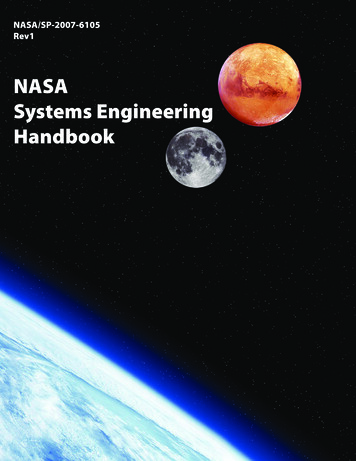
Orbital Debris Quarterly NewsMCATcontinued from page 5this end, a fully automated software packagehas been designed specifically for MCAT byEuclid Research of Canada to command thetelescope and dome, monitor weather andclouds, determine the priority of observing,collect data, and (during the following daytimehours), perform a standardized data reductionprocedure. This ‘reduced’ data will then be sentvia satellite to NASA ODPO for analysis.MCAT’s unique capabilities include foursophisticated observing modes that involveautomated detection, acquisition, tracking,and – via preliminary orbit generation andrefinement – re-acquisition of both GEO andLEO targets. They include: (1) GEO survey/GEO follow-up mode, (2) Catalog/Object ofInterest mode, (3) Orbit Scan mode (LEO), and(4) Stare-Detect-Chase mode (LEO). Figure 4shows the expected field mapping of the GEOfield at a snapshot in time (GEO survey). TheCatalog/Object of Interest mode tracks aknown target with known orbital parameters.The newer Orbit Scan mode tracks an expectedorbital rate to detect unknown objects. StareDetect-Chase mode detects streaks, and in realtime, calculates the expected orbital rate anddirection to chase the newly detected object. Inthe event of an explosion or collision, MCATaffords NASA the ability to rapidly respondto the event and track the time evolutionof the cloud of debris. For all modes, filterphotometry will be employed to characterizetargets (e.g., brightness measurements canbe used to estimate sizes or lightcurves forrotation/tumble rates).Other global sensors may also handoff targets to MCAT for better overall orbitdetermination. Through its unique longitude,MCAT can be used to support Space SituationalAwareness (SSA) and the Space SurveillanceNetwork (SSN) by providing astrometry,catalog maintenance, or catalog metrics datato U.S. Strategic Command (USSTRATCOM)or the Joint Space Operations Center (JSpOC).Here, the unique longitude of Ascensionbecomes a true asset. Combining this information with range to the target, one might alsogain insight into the shape of the target to giveintrinsic insight into the risks posed to GEOspacecraft by the object.SummaryNASA’s MCAT has the potential toimprove NASA’s understanding of the debrisenvironment significantly, which is essentialto ensuring the safety of all spacecraft in orbitaround the Earth. The new destination ofAscension Island offers a variety of benefits. Theunique latitude/longitude will fill a significantgap in the GEODSS network’s coverage ofthe sky. From an astronomical perspective, theenvironment is promising with limited rainfall,steady trade-winds producing laminar flow overthe island, potentially stable ‘seeing’ conditions,and dark skies. Personnel and infrastructuresupport at this remote location will be criticalfor the success of an automated telescope. Toaccomplish its goals, MCAT will employ fourmajor operational modes. All this is madepossible due to the marriage of sophisticatedautomated software, a suite of weather sensors,advanced instrumentation, a fast trackingtelescope and dome, and a very dedicated teamof engineers and scientists.For further information, see Lederer, et al. [3].References1. Stansbery, E.G., et al. Meter-ClassAutonomous Telescope for Space DebrisResearch, 2003 AMOS Technical ConferenceProceedings, 2003.2. Abercromby K.J., et al. MichiganOrbital Debris Survey Telescope (MODEST)Observations of the Geosynchronous OrbitalDebris Environment Observing Years: 20072009, NASA TP-2011-217350, 2011.3. Lederer, S.L., et al. The NASA MeterClass Autonomous Telescope: Ascension Island.AMOS Technical Conference Proceedings, 2013. Hypervelocity Impact Test with Large Mass ProjectileE. CHRISTIANSEN, A. DAVIS,J. MILLER, AND D. LEARA hypervelocity impact test was conductedwith a 598 g projectile at 6.905 km/s on aSteel meshBumperProjectile: 598 g,Al and NyloncylinderS1/2S1/2S1Fiberglass clothBumpersFigure 1. Diagram of multi-shock shield target.6NASA supplied multi-shock shield. Theprojectile was a hollow aluminum and nyloncylinder with an outside diameter of 8.6 cm andlength of 10.3 cm. This test was performedin February 2014 atArnold EngineeringDevelopmentComplex (AEDC)in preparation forthe DebriSat testto be conductedin April 2014.This pig g y-backopportunityS155cm 10cmwasgenerouslyprovided by theAEDCRangeKevlar rearTeam.Figu re 1wallsillustrates the multi-shock shield test ar ticle, which consistedof five separate bumpers, four of which werefiberglass fabric and one of steel mesh, andtwo rear walls, each consisting of Kevlarfabric. The overall length of the test articlewas 2.65 m. Figure 2 shows the test articleafter loading on a truck prior to shipping toAEDC.The test article was a 5X scaled-up versionof a smaller multi-shock shield previouslytested using a 1.4 cm diameter aluminumprojectile for an inflatable module projectseveral years ago. Hydrocode simulationswere performed prior to the impact test andindicated that some adjustments were neededto the shield to successfully stop the projectilein the AEDC test, primarily because thecylindrical shape was difficult to fragment.Therefore, a steel mesh bumper was addedcontinued on page 7
ed from page 6to the shield configuration to induce greaterfragmentation of the projectile. Figure 3illustrates the results of a hydrocode simulationindicating that shield penetration would occurwithout the steel mesh.The AEDC test occurred as planned, andthe NASA multi-shock shield was successfulat stopping the 598 g projectile (Figures 4 to5). The fifth bumper layer was not completelypenetrated, although it was torn free from itssupport structure and thrown into the first rearwall. The outer Kevlar layer of the first rearwall was torn (probably from the frame of thefifth bumper layer that impacted into the rearwall), but the back of the rear wall was intact(Figure 6). No damage occurred to the secondrear wall, or to the witness plate behind thetarget. The table below indicates the damageto each layer of the shield. The data from thistest will be used in updating the multi-shockshield ballistic limit equations. Figure 4. Post-test image of multi-shock shield target.First fiberglass bumper on right, Kevlar rear walls on left.Figure 2. Pre-test image of multi-shock shield target.Kevlar rear walls are on left.First fiberglass bumper is on right,Figure 5. Post-test image of multi-shock shield.Front view of target.Figure 3. Hydrocode simulation of multi-shock shield without steel mesh included. Impact directionleft to right. Shield rear wall failed (on right).Table 1. Multi-shock Shield Damage Measurements.Bumper 1:Fiberglass130 mmdiameterperforationBumper 2:Fiberglass300 mmdiameterperforationBumper 3:steel meshBumper 4:FiberglassBumper 5:FiberglassRear wall 1:KevlarRear wall 2:Kevlar600 mmdiameterperforation300 om shieldstructureNo completepenetration,bumperframedislocatedfrom shieldstructureTear onouter fabriclayer, nocompletepenetrationNo damageFigure 6. Post-test image of multi-shock shield.Kevlar rear walls are intact (no complete penetration).7
Orbital Debris Quarterly NewsDAS 2.0 NOTICETHE ORBITAL DEBRIS QUARTERLYNEWS IS PUBLISHED* ON:Attention DAS 2.0 Users: an updatedsolar flux table is available for use withDAS 2.0. Please go to the Orbital v/mitigate/das.html) to downloadthe updated table and subscribe for emailalerts of future updates.15 January15 April15 July15 OctoberVisit etter.html to view or download ODQN issues*When the 15th occurs on a weekend, the ODQNpublishes on the following MondayUPCOMING MEETINGS16-18 June 2014: 3rd EuropeanWorkshop on Space DebrisModeling and Remediation,Paris, FranceThe focus of the previous twoworkshops was on concepts and technologydevelopment for active debris removal oflarge and massive objects. The scope ofthe third workshop will expand to alsoinclude modeling of the future orbital debrisenvironment, removal of millimeter andlarger debris, and non-technical aspects oforbital debris environment remediation.The CNES will again organize and host thisbi-annual event at its headquarters in Paris.Additional information about the event canbe obtained from Dr. Christophe Bonnal at christophe.bonnal@cnes.fr .2-10 August 2014: 40th Committeeon Space Research (COSPAR)Scientific Assembly,Moscow, RussiaThe main theme of the Panel onPotentially Environmentally DetrimentalActivities in Space (PEDAS) for the 40thCOSPAR is “Space Debris Respondingto a Dynamic Environment.” The PEDASsessions will cover areas such as advancesin ground- and space-based observationsand methods for their exploitation; in-situ8measurement techniques; debris andmeteoroid environment models; debrisflux and collision risk for space missions;on-orbit collision assessment, re-entry riskassessments, debris mitigation and debrisenvironment remediation techniques andtheir effectiveness with regard to longterm environment stability; national andinternational debris mitigation standardsand guidelines; hypervelocity acceleratortechnologies; and on-orbit shieldingconcepts.Four half-day sessions areplanned. The abstract submission deadlineis 14 February 2014. Additional details ofthe 40th COSPAR are available at: https://www.cospar-assembly.org/ .have been planned to cover thesetopics. In addition, a joint session withthe Space Security Committee on thepolicy, legal, and economic aspectsof space debris will also be held. Thedeadline for abstract submission is25 February 2014. Additional details ofthe Congress are available at: 014 .29 Sep - 3 Oct 2014:65th InternationalAstronautical Congress (IAC),Toronto, CanadaThe 7th IAASS Conference,“Space Safety Is No Accident,” isan invitation to reflect and exchangeinformation on a number of topicsin space safety and sustainability ofnational and international interest.The 2014 conference will dedicatea set of specialized sessions onorbital debris, including space debrisremediation, reentry safety, spacesituational awareness and internationalspace traffic control, and commercialhumanspaceflightsafety.Thedeadline for abstract submission is30 May 2014. Additional details of theConference are available at: http://iaassconference2014.space-safety.org/ The Canadian Aeronautics andSpace Institute will host the 65th IACwith a theme of “Our World NeedsSpace.” Just like the previous IACs,the 2014 Congress will include aSpace Debris Symposium to addressthe complete spectrum of technicalissues of space debris measurements,modeling, risk assessments, reentry,hypervelocity impacts and protection,mitigation and standards, and spacesituational awareness. Seven sessions20-22 Oct 2014: 7th InternationalAssociation for Advancement ofSpace Safety (IAASS) Conference,Friedrichshafen, Germany
www.orbitaldebris.jsc.nasa.govINTERNATIONAL SPACE MISSIONS1 January 2014 – 31 March 2014Perigee ApogeeInclinationAltitude Altitude(DEG)(KM)(KM)SATELLITE BOX SCORE(as of 9 April 2014, cataloged by theU.S. SPACE SURVEILLANCE ion2014-001AGSAT 14INDIA35770358030.1102014-002ATHAICOM 6THAILAND35779357940.1102014-003ACYGNUS ORB-1USA40240751.610*1998-067(28 FLOCK 1 payloads)USACountry/OrganizationCHINARocketBodies& 311874137841289916683CIS*1998-067ELARDUSAT 2USA39240351.6JAPAN*1998-067EMUAPSAT 1998-067EPLITSAT 1LITHUANIA37338351.6*1998-067EQLITUANICASAT 1LITHUANIA38639751.62014-004ATDRS 12USA35776357927.0102014-005APROGRESS M-22MRUSSIA41141651.6102014-006AABS TALY 35783357900.02014-007ATURKSAT 4ATURKEY35773357980.1112014-008ANAVSTAR 69 (USA 38865.0112014-009BKSAT 9DOPUSATJAPAN35636365.02014-009ETEIKYOSAT 3JAPAN36738065.02014-009FITF 1JAPAN3
dedicated to NASA’s mission to characterize the space debris environment. It is the successor to a series of optical telescopes developed and operated by the NASA Orbital Debris Program Office (ODPO) to monitor and assess the debris environment in (1) low