Transcription
UC Berkeley Space Technologies and RocketryNASA Student Launch Preliminary Design ReviewProject Arktos432 Eshleman Hall, MC 4500Berkeley, CA 94720-4500November 3, 2017
Contents1 Summary of PDR Report1.1 Team Summary . . . . . . . . . . . . . . . . . . . . . . . . . . . . . . . . . .1.2 Launch Vehicle Summary . . . . . . . . . . . . . . . . . . . . . . . . . . . .1.3 Payload Summary . . . . . . . . . . . . . . . . . . . . . . . . . . . . . . . . .44442 Changes Made Since Proposal2.1 Airframe . . . . . . . . . . . .2.2 Payload . . . . . . . . . . . .2.3 Recovery . . . . . . . . . . . .2.4 Project Plan . . . . . . . . . .555663 Vehicle Criteria3.1 Airframe . . . . . . . . . . . . . . . . . . . .3.1.1 Mission Statement . . . . . . . . . .3.1.2 Success Criteria . . . . . . . . . . . .3.1.3 Objectives . . . . . . . . . . . . . . .3.1.4 Transition Piece . . . . . . . . . . . .3.1.5 Fins . . . . . . . . . . . . . . . . . .3.1.6 Motor Tube Design and Alternatives3.1.7 Motor Choice and Alternatives . . .3.1.8 Boat Tail Design Alternatives . . . .3.1.9 Nose Cone Choice and Alternatives .3.2 Design Metrics . . . . . . . . . . . . . . . .3.2.1 General Overview . . . . . . . . . . .3.2.2 Weight Distribution . . . . . . . . . .3.2.3 Length Distribution . . . . . . . . . .3.2.4 Mission Performance Predictions . .3.3 Requirements . . . . . . . . . . . . . . . . .66667799910111111121213174 Recovery Subsystem4.1 Component Analyses . . . .4.1.1 Avionics Bay . . . .4.1.2 Avionics Bay Door .4.1.3 Bulkheads . . . . . .4.1.4 Centering Rods . . .4.1.5 Bolts . . . . . . . . .4.1.6 Shock Cords . . . . .4.2 Deployment System . . . . .4.3 Drawings and Schematics . .4.4 Black Powder Calculations .4.5 Kinetic Energy Calculations4.5.1 Flight Plan . . . . .19191921222324242527323232.1.
4.6Rocket Locating Transmitters . . . . . . . . . . . . . . . . . . . . . . . . . .345 Safety5.1 Responsibilities . . . . . . . . . . . . . .5.2 Personnel Hazards Analysis . . . . . . .5.3 Failure Modes and Effects Analysis . . .5.4 Environmental Risks Analysis . . . . . .5.5 Project Risks and Consequences Analysis.3434343851536 Payload Criteria6.1 Payload Description/Objective .6.2 Payload Electrical Systems . . .6.3 Design Alternatives . . . . . . .6.3.1 Deployment . . . . . . .6.3.2 Ejection . . . . . . . . .6.3.3 Movement . . . . . . . .6.3.4 Solar . . . . . . . . . . .6.4 Vehicle Interfaces . . . . . . . 848585868686887 Project Plan7.1 NSL Handbook Requirements .7.1.1 General Requirements .7.1.2 Airframe Requirements .7.1.3 Payload Requirements .7.2 Team Derived Requirements . .7.2.1 General TDRs . . . . . .7.2.2 Payload TDRs . . . . .7.3 Budget . . . . . . . . . . . . . .7.3.1 Airframe Budget . . . .7.3.2 Recovery Budget . . . .7.3.3 Payload Budget . . . . .7.3.4 Outreach Budget . . . .7.4 Funding . . . . . . . . . . . . .7.4.1 Summary . . . . . . . .7.4.2 Description of Accounts7.4.3 Funding . . . . . . . . .7.4.4 Distribution of Funds . .7.4.5 Material Acquisition . .7.5 Timeline . . . . . . . . . . . . .7.5.1 Design Team Tasks . . .7.5.2 Outreach Events . . . .Appendix A List of Project Leaders90Appendix B Safety Agreement912
Appendix C NAR High Power Rocket Safety Code92Appendix D Matlab Code for Recovery943
1Summary of PDR Report1.1Team SummaryTeam Name:UC Berkeley Space Technologies and Rocketry (STAR)Team Contact Address432 Eshlemann Hall, MC 4500Berkeley, CA 94720-4500Team MentorDavid RaimondiPresident: Livermore Unit. National Association of Rocketry (LUNAR)NAR #82676, Level 31.2Launch Vehicle SummaryThe length of the launch vehicle is 113in. The wet weight of the launch vehicle is 27.13lbs and the dry weight is 22.19 lbs. The launch vehicle utilizes a Cesaroni L730 motor toachieve a simulated apogee of approximately 5555ft.The recovery system implements a same-side dual deployment method, with drogue chutedeployment at apogee and main chute deployment at 800ft AGL. The 24in elliptical droguechute and 72in toroidal main chute are systematically integrated with a series of two L2tender descenders and black powder ejection charges. The ejection is controlled by twoaltimeters, which sit on an avionics sled design. Furthermore, the avionics bay will beaccessible from the airframe exterior via a small door. Further launch vehicle details can befound on our Flysheet at https://stars.berkeley.edu/sl.html.1.3Payload SummaryThe goal of the payload experiment is to have an autonomous rover deploy from therocket, drive over five feet away, and deploy solar panels. The payload will be locatedabove the booster and recovery portions of the rocket and directly below the nosecone onthe launchpad and during ascent. After recovery and upon landing, a pneumatic cylinderwill activate and break two 40lb shear pins, separating the payload section from the lowertransition section. After separation, a scissor lift will activate, pushing the rover out of thepayload tube. Once the rover has emerged from the rocket, the rover will drive forwardapproximately 10ft to fulfill the handbook requirements. Upon stopping, it will deploy thesolar panels by rotating the hood of the rover up, revealing the two sheets of solar panels.For ease of organization, payload is split into four subsystems: Deployment - Separation of the payload section and the radio link Ejection - Ejecting the rover from the payload aiframe section Movement - Rover design and its movement away from the rocket Solar - Solar subsystem on the rover4
22.1Changes Made Since ProposalAirframeThe internal layout of the airframe has changed significantly since the proposal for NASASL 2018. Additionally, some external changes have resulted from the internal changes. Themajor change to the airframe is that the length of the rocket built from 6in tube has beenshortened significantly, and the length of the 4in section has been lengthened. This resultsin a lighter, more aerodynamic, and more stable rocket. In order to compensate for theseexternal changes, the avionics bay has been modified to fit in the section of 4in tubing.Additionally, the parachutes have been moved from the aft end of the avionics bay to thefore end of the avionics bay. As a result, the parachutes are deployed from a more centralizedlocation on the rocket. Additionally, the motor size has been reduced from a 75mm diameterto a 54mm diameter. The current motor in use is a Cesaroni L730, whereas an AerotechL1150 was used in the proposal. More accurate mass calculations were acquired from thepayload, electrical, and recovery subteams, and as a result, the overall weight of the rocketwas significantly reduced.2.2PayloadThe payload Deployment and Ejection plans have undergone major revisions since thelast proposal for NASA SL 2018. The original Deployment plan consisted of using a blackpowder charge on a permanent bulkhead that, when activated, would create a force capableof breaking the shear pins connecting the payload section to the rest of the airframe. Apre-compressed spring behind a protective bulkhead will eject said bulkhead through theopening on the bottom of the payload section, effectively making room for the rover to exitthe airframe.After analyzing the amount of force the black powder charge would produce, it wasdetermined that using black powder in close proximity to the rover payload would be illadvised. To avoid causing damage to the rover, the Deployment plan was changed to utilizea pneumatic ejection system to clear space for the ejection of the rover. This design shouldbe a safer and more reliable method of deployment.The original plan for Ejection involved using a large spring to force the rover out ofthe airframe, but that has since been changed to a scissor lift system. The primary reasonbehind this change is that a spring system would present undue risk in terms of damagingthe rover. In the previous design, because the spring would have been compressed prior tolaunch with the rover directly next to it, if the clasps securing the spring during flight brokeor otherwise failed prior to planned ejection, the rover would not be able to exit the airframeand could likely be damaged during the process. Any spring powerful enough to eject therover would be difficult to compress safely during packaging of the payload and may be toocomplicated and potentially unreliable during ejection. As a result, the design was modifiedto a scissor lift system that is more reliable, more controllable, and less dangerous to therover and airframe.For the most part, the design of the rover itself has remained the same except for onekey alteration: the body design. The body of the rover was originally going to be cylindrical5
to maximize space within the payload section of the rocket. The new plan is to have arectangular body to promote ease of manufacturing and mounting of parts. Most of theelectronics housed inside the rover’s body are rectangular, so having a rectangular body willallow for more efficient packing. Additionally, the solar panels will now be mounted on thehood of the rover on a shell in the main rover body to fully satisfy the solar panel unfoldingrequirement.2.3RecoveryThe parachute deployment system design has remained unchanged from the initial proposal. The avionics bay design has been updated. The decision was made to mount anI-beam-shaped sled vertically inside the avionics bay instead of using a horizontally-mountedsled. The sled will now be oriented along the flight path of the launch vehicle instead ofperpendicular to it. The sled will no longer have composite sheets above and below it andwill instead fit directly into the bulkheads. The change in sled orientation also leads to achange in bulkhead design. The bulkheads now consist of two one-fourth in pieces of plywood epoxied together, located in between the coupler and the airframe. Blue Tube willcontinued to be used as the material for the airframe and the coupler. The new design forthe sled still includes rails so that it may slide out for easy access, and the avionics bay willstill be accessed via a door. It has now been decided that this door will be secured duringflight by four screws, one at each corner.2.4Project PlanDue to project delays and a launch day cancellation due to fire concerns, the sub-scaletest flight has been moved from November 4th to December 2nd.3Vehicle Criteria3.13.1.1AirframeMission StatementOur mission is to successfully design, manufacture, and fly a fully capable rocket to 5280feet (1 mile) carrying a deployable rover with solar panel. This will serve as a test or trialrun for potential rover missions that NASA will conduct on Mars in the future.3.1.2Success Criteria Airframe is defined as any of the external tubing, coupler tubing, motor tubing, fins,nose cone, and transition piece. There will be no cracks in the airframe. There will be no unwanted separation between the pieces of the rocket. The stress in the airframe will not exceed acceptable levels. Acceptable is defined asbelow the yield strength for the specific member of tubing in question.6
Meets all vehicle requirements set from NASA SL 2018 Handbook.3.1.3Objectives To educate the public in rocketry To advance the technology in aerospace systems and rocketry To promote aerospace as a major at UC Berkeley3.1.4Transition PieceA key element in the design of our rocket is the addition of a transition piece, whichserves the purpose of reducing the rockets diameter. This causes a shift in the center ofgravity, which improves the rockets stability, giving more leeway in other parts of the designto add different kinds of elements that are not necessarily optimal for the stability.It is clear that a transition piece is essential to change the rockets diameter partwaythrough. In the case of a rocket with no transition where the nose cone is attached straightonto the body tube at the same diameter, the rocket can experience turbulence at the rearend. This turbulence can distort the flight path of the rocket, mitigating the effect of thefins. To counter this problem, the fins have to be larger to make the airflow smoother onthe rocket and improve the stability again. This much of a change in the fin size becomesimpractical, however, to then physically manage the rocket and minimize the chance of failureduring launch. Therefore, the only option left is to create a transition element - a part ofthe rockets body tube shaped like a frustum, resulting in a smooth change in diameter fromthat required by the payload and motor elements and the minimum feasible diameter at thenose cone.The transition piece can be customized in multiple configurations, which are mainlycharacterised by the length over which the diameter changes. A tradeoff then arises - alonger transition would improve airflow as it reduces drag, but the cost of an increasedsurface area and therefore increased materials costs.However, upon quantifying the increase in the surface area, it turned out to have arelatively insignificant effect on the overall cost. In addition, the cost of having the transitionpiece at all is offset by current plans of constructing it with facilities that are available tothe team (as will be detailed later on). Therefore, as the increase in cost is miniscule, andthe expense of having the piece at all is not a factor, there is no significant restriction on thespecifications of the transition piece thus far.Other factors somewhat restrict the dimensions of the transition piece. The pre-madenose cone that is being employed is compatible only with body tubes of specific diameters,of which 6in was the most practical since any less would reduce stability and any morewould reduce the positive impact of having a transition piece in the first place. In addition,payload components and the motor tubing require a minimum diameter of 6in. Therefore,the transition pieces fore and aft diameters are 6in and 4in respectively.Deciding on the length was more complicated, as it depends heavily on the complexsubject of airflow over the exterior of the rocket. Any change in the diameter, howevergradual, is bound to change these factors, so a decision must be made on how to balance7
the length with how drastic this change is. This was determined by running simulationsin OpenRocket for different values of the transition length, and looking at how it affectedthe flight path. For some values, no set of small changes in other parameters (e.g. finsize, payload mass, overall body tube length) was able to create a model with the requiredstability and apogee. Put another way, no possible rocket design could have a transition ofthat length without redesigning every other aspect. However, the range of feasible lengthswas larger than previously anticipated, from 4in to 12in.When the transition length was longer, the rocket’s descent between apogee and recoverydevice deployment was found to be slightly more gradual, but the margin between the two8
was small and not something on which a decision could be based off of. Therefore, a lengthof 8in was selected, in the middle of the previously-determined feasible range, and foundthat this gave an optimally desired apogee and stability.Issues associated with the addition of this transition include the possibility of it breakingapart during launch, which can be mitigated by the use of fiberglass in the construction ofthe transition piece. Additionally, it may make the manufacturing process more difficult,as well as aerodynamic analysis, but its inclusion provides clear benefits that outweigh this.Manufacturing will be carried out via a fiberglass layup on a 3D printed mold.In conclusion, the addition of a transition section presents clear benefits regarding therockets mass, stability, apogee, and tolerable error in other factors.3.1.5FinsA trapezoidal shape was chosen for the fins, as it is the optimal shape for reducing dragon the rocket. The size of the fins comes at a compromise between surface area and increasedstability. Large fins may provide more stability, but they also contribute to a larger drag forcedue to their increased surface area. Similarly, smaller fins imply less drag, but a potentiallyreduced stability as well. Ultimately, the finalized geometry, which is optimal for our rocket,is made of an 8in root chord, and a 6in tip chord, at a height of 5in.The fin material will be fiberglass, as it is the best combination of strength and weightthat fits our budget. The particular type of fiberglass that will be used is G10, also calledGarolite, which has a tensile strength of 7.2 0.3 · 107 P a, at a density of 2.0 · 103 kg/m3 .Adding an airfoil significantly reduces drag and increases the apogee. However, it makesthe manufacturing of the fins more challenging. It is crucial that the height-to-length ratioof the airfoil stay constant, meaning that as the length gets shorter, the fins are at risk ofbeing too thin and breaking off. Additionally, it is important to note that a large apogeecan be detrimental, as that could lead to the disqualification of the team. For this reason,it was ultimately decided that the fins will not have an airfoil such that the cross-section ofthe fins is a rectangle. To compensate for the induced drag force, the edges of the fins willbe filleted, such that they are rounded off.3.1.6Motor Tube Design and AlternativesThe motor tube design was primarily motivated by the design of the rest of the airframe.A 4in diameter lower end and minimization of overall length led to the general geometry ofthe motor tube. The geometry was also decided upon in tandem with the motor choice. Thespecific length (26in) and diameter (Outer: 2.276in, Inner: 2.152in) were chosen to properlyfit the chosen motor.The material used for the motor tube is kraft phenolic. From our research, kraft phenolicoffers the best heat resistivity and strength for the price. Other options that were consideredwere Blue Tube (low heat resistivity), fiberglass (expensive), and carbon fiber (expensive).3.1.7Motor Choice and AlternativesMotor choice was governed by the rest of the airframe design, similarly to the motor tube.The Cesaroni L730 best suits our current design with the goals of minimizing rocket length,9
providing safe apogee approximation, and capitalizing on use of the boat tail. Other motorssuch as the Cesaroni L990-BS produced similar results but increased our expected maximumacceleration too much (around 30%). An additional alternative motor is the Animal WorksL777 which gives a similar apogee. The local supplier for rocket motors used by CalSTARcurrently does not carry motors manufactured by Animal Motor Works, so the CesaroniL730 was chosen over it.3.1.8Boat Tail Design AlternativesSub-Scale Boat TailThere will be no boat tail or tailcone retainer on the subscale rocket. This is due tothe very similar outer diameters of the booster tubing and the motor retention cap. Due tothe small transition in diameters between the motor tube and the end of the booster tube,manufacturing a boat tail to fit over the motor retention cap would yield a boat tail withan inclination angle around 2 degrees, which is too low to sufficiently reduce drag. Sincethis would negligibly reduce base drag but still add mass to the vehicle, this design was notselected.One of the possible ways to compensate for the large diameter of the motor retentionsystem would be to have a tailcone retention cap, where the boat tail also functions asthe retention cap. In this way, a smaller base diameter can be achieved for the boat tail,decreasing the amount of base drag. Several of these tailcone retainer caps are availablefor purchase from multiple vendors, however none of them are the correct diameters to fitboth the 2.56in Blue Tube and a 54mm motor. Manufacturing this part in house would bedifficult with the machinery accessible to the team. Even if we could manufacture this part,the reduction in drag would not be as significant as on the full scale rocket. The difficultyin manufacturing and the relatively low reduction in drag led to opting out of this designchoice.Full Scale Boat TailA conical fiberglass boat tail will be manufactured with a forward diameter of 4.014in, anaft diameter of 2.465in, and a length of 4.7in. The aft end of the boat tail will be rounded outvia sanding, and the boat tail should fit snugly around the motor retention system. Therewill be a section of coupler 0.5in in length on the forward end of the boat tail so that it canbe fitted and secured correctly to the end of the rocket.A conical boat tail was selected over several other shapes, such as ogive and power series.These other shapes may be beneficial for longer boat tails or wider rockets, but for our rocketa conical boat tail was best. This was primarily determined via OpenRocket Data.The dimensions of the boat tail could have been different in order to minimize basedrag; however, our design had a major constraint in the motor retention system. The innerdiameter of the base of the boat tail is designed to fit around the motor retainer, and thelength was determined by optimizing the boat tail transition angle to roughly 9 degrees.This serves to maximize the rediction of base drag, as confirmed by OpenRocket apogeesimulations.10
Fiberglass was chosen as the material for our boat tail over plastic, aluminum, and a fewother materials. Aluminum and other metals are difficult and expensive to manufacture, andplastics do not have sufficient heat resistance to survive in such close proximity to the thrustexhaust. Thus, fiberglass cured with high temperature epoxy was selected as our material,as it can be easily manufactued to our specifications and can withstand the stresses of theenvironment.3.1.9Nose Cone Choice and AlternativesThe nose cone choice accompanying the rocket design is intended to minimize inflicteddrag and overall rocket mass. As the rocket is designed for subsonic flight, nose cones of ogivegeometry are economically and aerodynamically ideal. Additionally, the aforementionedconstraints of drag and mass further favor nose cones of minimum size and weight Suchconstraints indicate that a fiberglass is the ideal material for this rocket due to its highcompressive strength and low weight. In accordance with Student Launch guidelines, thenose cone cannot be manufactured in-house, and must be one commercially available bya third-party enterprise. As a result, the optimal nose cone choice for this rocket wouldbe an ogive, fiberglass nose cone of a diameter of 6in and a tip-to-shoulder length of 24in,as this is the smallest and lightest nose cone that is commercially available. Alternativesfor nose cone choice are conical, fiberglass nose cones of 6in diameter and 30in length, andogive, fiberglass nose cones of 6in diameter and 30in length. However, as these nose conessignificantly increase overall mass (by roughly 8oz), as well as net drag as modelled byOpenRocket, the preference of nose cone aligns with the design of the aforementioned nosecone.3.23.2.1Design MetricsGeneral Overview Length: 9.42 ft11
Wet Weight: 27.125 lbs Dry Weight: 24.14 lbs Apogee: 5555ft Maximum Velocity: 0.54 Mach Maximum Acceleration: 8.95 g Stability: 2.41 cal3.2.2Weight Distribution Electrical: Electrical will be permitted 2 lbs of mass in the nose cone and an additional2 lbs for avionics. Avionics will be located in the ”Booster ” body tube. Payload: Payload will be given 6 lbs to use for the rover and deployment system. Thismass will be placed in the payload tube. Recovery: For recovery the subteam is allowed a total of 1.568 lbs of equipment plusapproximately an additional 13 lbs for miscellaneous parts. Of the 1.568 lbs, the mainparachute weighs 0.811 lbs, the drogue parachute weighs 0.134 lbs, and the shock cordweighs 0.623 lbs. This mass will be located in the recovery tube. Propulsion: 4.9 lbs (wet mass) will be dedicated to the booster section of the rocket. Airframe: The remaining weight (9.849 lbs) is for the airframe of the rocket. Thisweight will be spread among the body tubes, structural elements, and fins of therocket.3.2.3Length Distribution Nose Cone: The rocket will use 24in long fiberglass ogive nose cone made in a 4:1length to diameter ratio. This space will be made available for payload and electronicsequipment. Payload Tube: Payload is permitted an 18in by 6in OD body tube for their rover anddeployment system. Transition Piece: The rocket will utilize an 8in transition piece with a fore OD of 6inand an aft OD of 4in.– Payload Coupler: The transition piece will have a coupler on the fore end thatextends 3in into the payload tube. Payload will still have access to this space.– Recovery Coupler: On the aft end of the transition piece will be a 4in couplerthat extends into the recovery tube. This space will still be usable by recovery.12
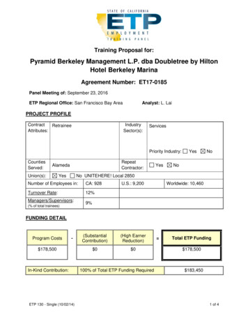
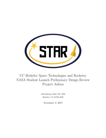
Recovery Tube: The recovery subteam will have 26in of body tube to store parachutes,shock cord, and any other equipment that will be needed. This section of the rockethas an OD of 4in. Avionics Bay Tube: Electrical will have a 7in by 4in OD body tube to store the rocket’sflight computers.– Avionics Bay Coupler: The coupler between the recovery tube, avionics bay, andbooster tube will be one 15in piece that runs through the entire avionics bay. Booster: The booster section of the rocket will be 26in long and will house the motortube and centering rings. At the aft end of the booster tube will be a set of threefiberglass fins to stabilize the rocket in flight. Boat Tail: The rocket will have a boat tail that is 4.7in long to reduce drag. The boattail will bridge the gap between the 4in body tube and the end of the motor retainer.3.2.4Mission Performance PredictionsThe projected altitude of the rocket is 5555ft. Although this projection is currently abovethe maximum allowed altitude, we predict that some sections of the rocket may ultimatelybe heavier than our current prediction. Additionally, ballast can be added to the rocket inorder to increase weight and reduce apogee.The maximum velocity of the rocket during flight is Mach 0.55. The maximum acceleration is 8.83 Gs, and the motor provides a maximum thrust of 273.59 lbf. Flight simulationresults are illustrated in Figure 1.The mass of the payload section is projected to be 6 lbs. The mass of the avionics bay isprojected to be approximately 2 lbs. The remainder of the rocket, including the rest of theairframe, the motor, and the parachutes are projected to weigh approximately 21.125 lbs.The total weight of the rocket is 27.125 lbs.The static stability margin is calculated to be 2.41 calibers. The center of pressure islocated 78.2in from the tip of the nose cone, and the center of gravity is located 63.6in fromthe tip of the nose cone.13
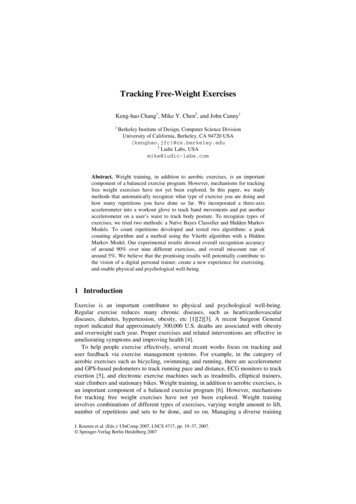
Figure 1: Flight SimulationsFigure 3: The total drift of the rocket with 5 mph wind is approximately 330ft.14
Figure 2: The total drift of the rocket with no wind is approximately 9.5ft.Figure 4: The total drift of the rocket with 10 mph wind is approximately 775ft.15
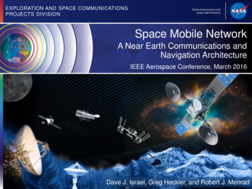
Figure 5: The total drift of the rocket with 15 mph wind is approximately 1300ft.Figure 6: The total drift of the rocket with 20 mph wind is approximately 1750ft.16
3.3RequirementsRequirementThe vehicle shall deliver thescience or engineering payload to an apogee altitudeof 5,280ft above groundlevel.Verification PlanOpenRocketsimulationsand the Perfectflite Stratologger CF Altimeter willverify that the design andan Cesaroni TechnologyL730-P motor meets thealtitude requirement.The vehicle shall carryone commercially available,barometric altimeter forrecording the official altitude used in determiningthe altitude award winner.The launch vehicle shall bedesigned to be recoverableand reusable. Reusable isdefined as being able tolaunch again on the sameday without repairs or modifications.The launch vehicle shallhave a maximum of four (4)independent sections. Anindependent section is defined as a section that is either tethered to the mainvehicle or is recovered separately from the main vehicleusing its own parachute.The launch vehicle shall belimited to a single stage.A Perfectflite Stratologgeraltimeter will be used torecord the official attitude.The launch vehicle shall becapable of being preparedfor flight at the launchsite within 4 hours, fromthe time the Federal Aviation Administration flightwaiver opens.Assembly and pre-launchche
I-beam-shaped sled vertically inside the avionics bay instead of using a horizontally-mounted sled. The sled will now be oriented along the ight path of the launch vehicle instead of perpendicular to it. The sled will no longer have composite sheets above and