Transcription
VELTECH HIGHTECH Dr.RANGARAJAN Dr.SAKUNTHALA ENGINEERING COLLEGEDEPARTMENT OF COMPUTER SCIENCE AND ENGINEERINGCS6502- OBJECT ORIENTED ANALYSIS AND DESIGNUNIT – IIntroduction to OOAD – Unified Process - UML diagrams – Use Case – Class Diagrams–Interaction Diagrams – State Diagrams – Activity Diagrams – Package, component andDeployment Diagrams.1. Introduction to OOAD1.1 What is analysis and design?Analysis emphasizes an investigation of the problem and requirements, rather than asolution. For example, if a new computerized library information system is desired, how it willbe used.Design emphasizes a conceptual solution that fulfills the requirements, rather than itsimplementation. For example, a description of a database schema and software objects.1.2 What is object oriented analysis and design? (April/May 2011, 2017)During object oriented analysis, there is an emphasis on finding and describing theobjects or concepts in the problem domain. For example, in the case of the library informationsystem, some of the concepts include book, library and patron.During object oriented design, there is an emphasis on defining software objects and howthey collaborate to fulfill the requirements. For example, in the library system, a book softwareobject may have a title attribute and a get chapter method1.3 Define Object. (Nov/Dec 2009)An object is a real-world element in an object–oriented environment that may have aphysical or a conceptual existence. Each object has: Identity that distinguishes it from other objects in the system. State that determines the characteristic properties of an object as well as the values of theproperties that the object holds. Behavior that represents externally visible activities performed by an object in terms ofchanges in its state.Objects can be modeled according to the needs of the application. An object may have aphysical existence, like a customer, a car, etc.; or an intangible conceptual existence, like aproject, a process, etc.1.4 ClassVELTECH HIGHTECH Dr.RANGARAJAN Dr.SAKUNTHALA ENGINEERING COLLEGEPage 1
VELTECH HIGHTECH Dr.RANGARAJAN Dr.SAKUNTHALA ENGINEERING COLLEGEDEPARTMENT OF COMPUTER SCIENCE AND ENGINEERINGA class represents a collection of objects having same characteristic properties thatexhibit common behavior. It gives the blueprint or description of the objects that can be createdfrom it.Creation of an object as a member of a class is called instantiation. Thus, object is aninstance of a class.The constituents of a class are: A set of attributes for the objects that are to be instantiated from the class. Generally,different objects of a class have some difference in the values of the attributes. Attributes areoften referred as class data. A set of operations that portray the behavior of the objects of the class. Operations arealso referred as functions or methods.1.5 EncapsulationEncapsulation is the process of binding both attributes and methods together within aclass. Through encapsulation, the internal details of a class can be hidden from outside. Itpermits the elements of the class to be accessed from outside only through the interface providedby the class.1.6 Data HidingTypically, a class is designed such that its data (attributes) can be accessed only by itsclass methods and insulated from direct outside access. This process of insulating an object’sdata is called data hiding or information hiding.1.7 Message PassingAny application requires a number of objects interacting in a harmonious manner.Objects in a system may communicate with each other using message passing. The features ofmessage passing are: Message passing between two objects is generally unidirectional. Message passing enables all interactions between objects. Message passing essentially involves invoking class methods. Objects in different processes can be involved in message passing.1.8 InheritanceInheritance is the mechanism that permits new classes to be created out of existingclasses by extending and refining its capabilities. The existing classes are called the baseclasses/parent classes/super-classes, and the new classes are called the derived classes/childclasses/subclasses.The subclass can inherit or derive the attributes and methods of the super-class(es)provided that the super-class allows so. Inheritance defines an “is – a” relationship.Types of Inheritance: Single Inheritance : A subclass derives from a single super-class.VELTECH HIGHTECH Dr.RANGARAJAN Dr.SAKUNTHALA ENGINEERING COLLEGEPage 2
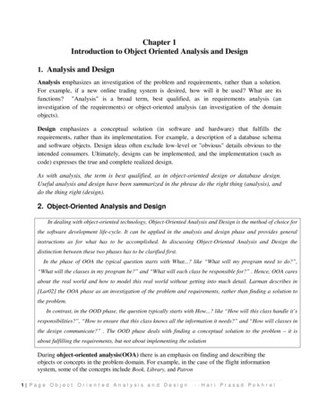
VELTECH HIGHTECH Dr.RANGARAJAN Dr.SAKUNTHALA ENGINEERING COLLEGEDEPARTMENT OF COMPUTER SCIENCE AND ENGINEERING Multiple Inheritance : A subclass derives from more than one super-classes. Multilevel Inheritance : A subclass derives from a super-class which in turn isderived from another class and so on. Hierarchical Inheritance : A class has a number of subclasses each of whichmay have subsequent subclasses, continuing for a number of levels, so as to form a treestructure. Hybrid Inheritance : A combination of multiple and multilevel inheritance so asto form a lattice structure.The following figure depicts the examples of different types of inheritance.1.9 PolymorphismPolymorphism is originally a Greek word that means the ability to take multiple forms. Inobject-oriented paradigm, polymorphism implies using operations in different ways, dependingVELTECH HIGHTECH Dr.RANGARAJAN Dr.SAKUNTHALA ENGINEERING COLLEGEPage 3
VELTECH HIGHTECH Dr.RANGARAJAN Dr.SAKUNTHALA ENGINEERING COLLEGEDEPARTMENT OF COMPUTER SCIENCE AND ENGINEERINGupon the instance they are operating upon. Polymorphism allows objects with different internalstructures to have a common external interface. Polymorphism is particularly effective whileimplementing inheritance.1.10 Generalization and SpecializationGeneralization and specialization represent a hierarchy of relationships between classes,where subclasses inherit from super-classes.Generalization:In the generalization process, the common characteristics of classes are combined to forma class in a higher level of hierarchy, i.e., subclasses are combined to form a generalized superclass. It represents an “is – a – kind – of” relationship. For example, “car is a kind of landvehicle”, or “ship is a kind of water vehicle”.Specialization:Specialization is the reverse process of generalization. Here, the distinguishing featuresof groups of objects are used to form specialized classes from existing classes. It can be said thatthe subclasses are the specialized versions of the super-class. The following figure shows anexample of generalization and specialization.1.11 Links and AssociationLink:A link represents a connection through which an object collaborates with other objects.Through a link, one object may invoke the methods or navigate through another object. A linkdepicts the relationship between two or more objects.Association:VELTECH HIGHTECH Dr.RANGARAJAN Dr.SAKUNTHALA ENGINEERING COLLEGEPage 4
VELTECH HIGHTECH Dr.RANGARAJAN Dr.SAKUNTHALA ENGINEERING COLLEGEDEPARTMENT OF COMPUTER SCIENCE AND ENGINEERINGAssociation is a group of links having common structure and common behavior.Association depicts the relationship between objects of one or more classes. A link can bedefined as an instance of an association.Degree of an AssociationDegree of an association denotes the number of classes involved in a connection. Degreemay be unary, binary, or ternary. A unary relationship connects objects of the same class. A binary relationship connects objects of two classes. A ternary relationship connects objects of three or more classes.Cardinality Ratios of AssociationsCardinality of a binary association denotes the number of instances participating in anassociation. There are three types of cardinality ratios, namely: One–to–One : A single object of class A is associated with a single object of class B. One–to–Many : A single object of class A is associated with many objects of class B. Many–to–Many : An object of class A may be associated with many objects of class Band conversely an object of class B may be associated with many objects of class A.1.12 Aggregation or CompositionAggregation or composition is a relationship among classes by which a class can be madeup of any combination of objects of other classes. It allows objects to be placed directly withinthe body of other classes. Aggregation is referred as a “part–of” or “has–a” relationship, with theability to navigate from the whole to its parts. An aggregate object is an object that is composedof one or more other objects.Aggregation may denote: Physical containment : Example, a computer is composed of monitor, CPU, mouse,keyboard, and so on. Conceptual containment : Example, shareholder has–a share.2. Unified ProcessWhat do you mean by Unified process in OOAD? (Nov/Dec 2011,May/Jun 2016, April/May2017)Unified Process is a popular iterative process for projects using object oriented analysisand design. UP make use of best practices such as iterative life cycle and risk-driverdevelopment to provide a well documents process description.The Unified Process supports the following1. Evolution of project plans, requirements and software architecture with well definedsynchronization points2. Risk management3. Evolution of system capabilities through demonstrations of increasing functionalityVELTECH HIGHTECH Dr.RANGARAJAN Dr.SAKUNTHALA ENGINEERING COLLEGEPage 5
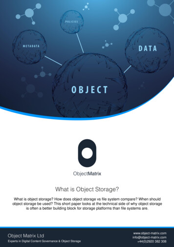
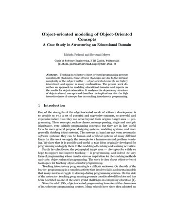
VELTECH HIGHTECH Dr.RANGARAJAN Dr.SAKUNTHALA ENGINEERING COLLEGEDEPARTMENT OF COMPUTER SCIENCE AND ENGINEERINGIt emphasizes the difference between engineering and production. Engineering Stage Driven by less predictable but smaller teams, focusing on design and synthesisactivities Production Stage Driven by more predictable but larger teams, focusing on construction, test anddeployment activitiesBriefly explain the Iterative and Evolutionary Development2.1 Iterative and Evolutionary Development In this lifecycle approach, development is organized into a series of short, fixedlength (for example, three-week) mini-projects called iterations; the outcome of each is a tested,integrated, and executable partial system. Each iteration includes its own requirements analysis, design, implementation, andtesting activities. The system grows incrementally over time, iteration by iteration, and thus thisapproach is also known as iterative and incremental development (see Fig1 given below). Because feedback and adaptation evolve the specifications and design, it is alsoknown as iterative and evolutionary development.Fig1. Iterative and evolutionary development.Briefly explain the different phases of unified process.(April/May 2011,Nov/Dec 2011,May/June 2012, Nov/Dec 2011,Nov/Dec 2015, May/Jun 2016, April/May 2017).VELTECH HIGHTECH Dr.RANGARAJAN Dr.SAKUNTHALA ENGINEERING COLLEGEPage 6
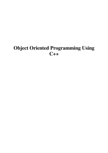
VELTECH HIGHTECH Dr.RANGARAJAN Dr.SAKUNTHALA ENGINEERING COLLEGEDEPARTMENT OF COMPUTER SCIENCE AND ENGINEERING2.2 Phases in the Unified ProcessThe two stages of the Unified Process are decomposed into four distinct phasesEngineering stage1. Inception - approximate vision, business case, scope, vague estimates.2. Elaboration - refined vision, iterative implementation of the core architecture,resolution of high risks, identification of most requirements and scope, more realisticestimates.Production phase3. Construction - iterative implementation of the remaining lower risk and easierelements, and preparation for deployment.4. Transition - beta tests, deployment.Fig2. Schedule-oriented terms in the UP.2.3 The UP Disciplines (was Workflows)The UP describes work activities, such as writing a use case, within disciplines(originally called workflows).In the UP, an artifact is the general term for any work product: code, Web graphics,database schema, text documents, diagrams, models, and so on. There are several disciplines inthe UP; focuses on some artifacts in the following three: Business Modeling— When developing a single application, this includes domainobject modeling. When engaged in large-scale business analysis or business processreengineering, this includes dynamic modeling of the business processes across the entireenterprise.VELTECH HIGHTECH Dr.RANGARAJAN Dr.SAKUNTHALA ENGINEERING COLLEGEPage 7
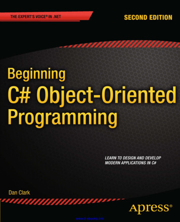
VELTECH HIGHTECH Dr.RANGARAJAN Dr.SAKUNTHALA ENGINEERING COLLEGEDEPARTMENT OF COMPUTER SCIENCE AND ENGINEERING Requirements—Requirements analysis for an application, such as writing uses casesand identifying non-functional requirements. Design—All aspects of design, including the overall architecture, objects, databases,networking, and the like.Disciplines and PhasesFig3. Disciplines and phasesAs illustrated in Fig3, during one iteration work goes on in most or all disciplines.However, the relative effort across these disciplines changes over time. Early iterations naturally tend to apply greater relative emphasis to requirements anddesign, and later ones less so, as the requirements and core design stabilize through a process offeedback and adaptation.Relating this to the UP phases, In elaboration, the iterations tend to have a relatively high level of requirements anddesign work, although definitely some implementation as well. During construction, the emphasis is heavier on implementation and lighter onrequirements analysis.2.4 The Agile UPo Methodologists speak of processes as heavy vs. light, and predictive vs. adaptive.o A heavy process is a pejorative term meant to suggest one with the followingqualities: many artifacts created in a bureaucratic atmosphere rigidity and control elaborate, long-term, detailed planning predictive rather than adaptiveVELTECH HIGHTECH Dr.RANGARAJAN Dr.SAKUNTHALA ENGINEERING COLLEGEPage 8
VELTECH HIGHTECH Dr.RANGARAJAN Dr.SAKUNTHALA ENGINEERING COLLEGEDEPARTMENT OF COMPUTER SCIENCE AND ENGINEERINGo A predictive process is one that attempts to plan and predict the activities andresource (people) allocations in detail over a relatively long time span, such as the majority of aproject.o In contrast, an adaptive process is one that accepts change as an inevitable driverand encourages flexible adaptation; they usually have an iterative lifecycle.o An agile process implies a light and adaptive process, nimble in response to changingneeds.o The UP was not meant by its authors to be either heavy or predictive, although itslarge optional set of activities and artifacts have understandably led to that of an agile process—agile UP.o A detailed plan (called the Iteration Plan) only plans with greater detail one iterationin advance.o Detailed planning is done adaptively from iteration to iteration.o Planning iterative projects, and the justification for this approach.o The case study emphasizes a relatively small number of artifacts, and iterativedevelopment, in the spirit of an agile UP.What are the benefits of Iterative development?2.5 Benefits of Iterative DevelopmentBenefits of iterative development include: Early rather than late mitigation of high risks (technical, requirements,objectives, usability, and so forth) Early visible progress Early feedback, user engagement, and adaptation, leading to a refined systemthat more closely meets the real needs of the stakeholders Managed complexity; the team is not overwhelmed by "analysis paralysis" orvery long and complex steps The learning within an iteration can be methodically used to improve thedevelopment process itself, iteration by iteration3. Unified Modelling Language (UML)What is UML? (May/June 2012, April/May 2017) UML stands for “Unified Modeling Language”It is a industry-standard graphical language for specifying, visualizing, constructing, anddocumenting the artifacts of software systems The UML uses mostly graphical notations to express the OO analysis and design ofsoftware projects. Simplifies the complex process of software design3.1 Why UML for ModellingVELTECH HIGHTECH Dr.RANGARAJAN Dr.SAKUNTHALA ENGINEERING COLLEGEPage 9
VELTECH HIGHTECH Dr.RANGARAJAN Dr.SAKUNTHALA ENGINEERING COLLEGEDEPARTMENT OF COMPUTER SCIENCE AND ENGINEERING Use graphical notation to communicate more clearly than natural language (imprecise)and code (too detailed).Help acquire an overall view of a system.UML is not dependent on any one language or technology.UML moves us from fragmentation to standardization.List various UML diagrams and explain the purpose of each diagram. (May/June2014,May/June 2016, April/May 2017)3.2 Types of UML DiagramsStructure Diagrams- Structure diagrams emphasize on the things that must be present in the system beingmodeled.- Since structure diagrams represent the structure, they are used extensively indocumenting the software architecture of software systems.Behavioural Diagrams- Behavior diagrams emphasize on what must happen in the system being modeled.- Since behavior diagrams illustrate the behavior of a system, they are used extensively todescribe the functionality of software systems.VELTECH HIGHTECH Dr.RANGARAJAN Dr.SAKUNTHALA ENGINEERING COLLEGEPage 10
VELTECH HIGHTECH Dr.RANGARAJAN Dr.SAKUNTHALA ENGINEERING COLLEGEDEPARTMENT OF COMPUTER SCIENCE AND ENGINEERING4. USE CASE DIAGRAMFor any scenario draw the use case diagram in detail and explain. (May/June 2015,April/May2011, May/June 2012,May/June 2014)Define use case diagrams.(nov/dec 2011, may/june 2012) A use case diagram describes how a system interacts with outside actors. It is a graphical representation of the interaction among the elements and system. Each use case representation a piece of functionality that a system provides to its user. Use case identifies the functionality of a system.A use case diagram contains four components. The boundary, which defines the system of interest in relation to the world around it. The actors, usually individuals involved with the system defined according to their roles. The use cases, which the specific roles are played by the actors within and around thesystem. The relationships between and among the actors and the use cases.Purpose: The main purpose of the use case diagram is to capture the dynamic aspect of a system. Use case diagram shows, what software is suppose to do from user point of view. It describes the behavior of system from user’s point. It provides functional description of system and its major processes. Use case diagram defines the scope of the system you are building.When to Use: Use Cases Diagrams Use cases are used in almost every project. They are helpful in exposing requirements and planning the project. During the initial stage of a project most use cases should be defined.VELTECH HIGHTECH Dr.RANGARAJAN Dr.SAKUNTHALA ENGINEERING COLLEGEPage 11
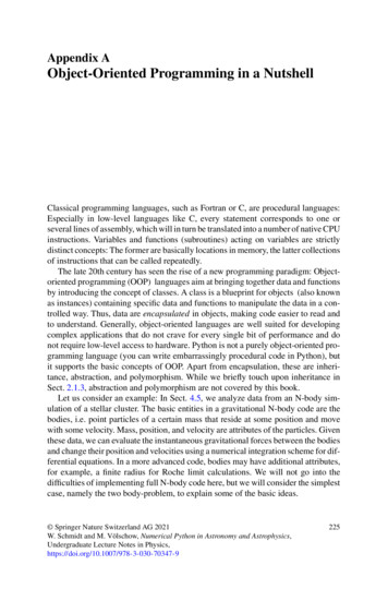
VELTECH HIGHTECH Dr.RANGARAJAN Dr.SAKUNTHALA ENGINEERING COLLEGEDEPARTMENT OF COMPUTER SCIENCE AND ENGINEERING5. CLASS DIAGRAMFor any scenario draw the class diagram in detail and explain. (May/June 2012, 2015,Nov/Dec 2011)Introduction The class diagram is a static diagram. A class model captures the static structure of a system by characterizing the objects in thesystem, the relationship between the objects, and the attributes and operations for each class ofobjects. The class diagram can be mapped directly with object oriented languages. Class diagram provide a graphical notation for modeling classes and their relationship.Purpose Analysis and design of the static view of an application. Describe responsibilities of a system. Base for component and deployment diagrams.When to use: Class Diagram Useful for Forward and Reverse engineering. Class diagrams are useful both for abstract modeling and for designing actualprograms. Developer uses class diagram for implementation decision.Sample Class DiagramVELTECH HIGHTECH Dr.RANGARAJAN Dr.SAKUNTHALA ENGINEERING COLLEGEPage 12
VELTECH HIGHTECH Dr.RANGARAJAN Dr.SAKUNTHALA ENGINEERING COLLEGEDEPARTMENT OF COMPUTER SCIENCE AND ENGINEERING6. STATE CHART DIAGRAMFor any scenario draw the state chart/ state machine diagram in detail andexplain.(May/June 2015,2014,Nov/Dec2011)Introduction A state diagram is a graph in which nodes correspond to states and directed arcscorrespond to transitions labeled with event names. A state diagram combines states and events in the form of a network to model allpossible object states during its life cycle, helping to visualize how an object responds todifferent stimuli.o A state diagram is a graph whose nodes are states and whose directed arcs aretransitions between states.o A state diagram specifies the state sequence caused by event sequence.Purpose The state model describes those aspects of objects concerned with time and thesequencing of operations events that mark changes, states that define the context for events, andthe organization of events and states. They are used to give an abstract description of the behavior of a system. It provides direction and guidance to the individual counties within the states. It specifies the possible states, what transitions are allowed between states. It describes the common behavior for the objects in a class and each object changesits behavior from one state to another.When to use: State Diagramo They are perfectly useful to model behavior in real time system.VELTECH HIGHTECH Dr.RANGARAJAN Dr.SAKUNTHALA ENGINEERING COLLEGEPage 13
VELTECH HIGHTECH Dr.RANGARAJAN Dr.SAKUNTHALA ENGINEERING COLLEGEDEPARTMENT OF COMPUTER SCIENCE AND ENGINEERINGo Each state represents a named condition during the life of an object during which itsatisfies some condition or waits for some event.o It determines how objects of that class react to events.o For each object state, it determines what actions the object will perform when itreceives an event.Sample State Diagram7. INTERACTION DIAGRAMFor any scenario draw the interaction diagram in detail and explain. (May/June2011,2015,Nov/Dec 2012)This interactive behaviour is represented in UML by two diagrams known as Sequence Diagram Collaboration Diagram7.1 SEQUENCE DIAGRAM (INTERACTION DIAGRAM)Introduction Sequence diagrams model the dynamic aspects of a software system. The emphasis is on the “sequence” of messages rather than relationship betweenobjects. A sequence diagram maps the flow of logic or flow of control within a usagescenario into a visual diagram enabling the software architect to both document andvalidate the logic during the analysis and design stages. Sequence diagrams provide more detail and show the message exchanged among aset of objects over time.Purpose The main purpose of this diagram is to represent how different business objectsinteract.VELTECH HIGHTECH Dr.RANGARAJAN Dr.SAKUNTHALA ENGINEERING COLLEGEPage 14
VELTECH HIGHTECH Dr.RANGARAJAN Dr.SAKUNTHALA ENGINEERING COLLEGEDEPARTMENT OF COMPUTER SCIENCE AND ENGINEERING A sequence diagram shows object interactions arranged in time sequence. It depicts the objects and classes involved in the scenario and the sequence ofmessages Exchanged between the objects needed to carry out the functionality of the scenario.When to use: Sequence Diagram Sequence diagram can be a helpful modeling tool when the dynamic behavior ofobjects needs to be observed in a particular use case or when there is a need forvisualizing the “big picture of message flow”. A company’s technical staff could utilize sequence diagrams in order to documentthe behavior of a future system.7.2 COLLABORATION DIAGRAM (INTERACTION DIAGRAM) The second interaction diagram is collaboration diagram. It shows the objectorganization as shown below. Here in collaboration diagram the method call sequence isindicated by some numbering technique as shown below. The number indicates how the methods are called one after another. We have takenthe same order management system to describe the collaboration diagram. The method calls aresimilar to that of a sequence diagram. But the difference is that the sequence diagram does not describe the objectorganization where as the collaboration diagram shows the object organization.VELTECH HIGHTECH Dr.RANGARAJAN Dr.SAKUNTHALA ENGINEERING COLLEGEPage 15
VELTECH HIGHTECH Dr.RANGARAJAN Dr.SAKUNTHALA ENGINEERING COLLEGEDEPARTMENT OF COMPUTER SCIENCE AND ENGINEERING8. ACTIVITY DIAGRAMFor any scenario draw the activity diagram in detail and explain.(May/June 2011, 2015,Nov/Dec 2011)Introduction An activity diagram is a type of flow chart with additional support for parallelbehavior. This diagram explains overall flow of control. Activity diagram is another important diagram in UML to describe dynamic aspectsof the system. Activity diagram is basically a flow chart to represent the flow from one activity toanother activityPurpose Contrary to use case diagrams, in activity diagrams it is obvious whether actors canperform Business use cases together or independently from one another. Activity diagrams allow you to think functionally.When to use: Activity Diagrams Activity diagrams are most useful when modeling the parallel behavior of amultithreaded system or when documenting the logic of a business process. Because it is possible to explicitly describe parallel events, the activity diagram is wellsuited for the illustration of business processes, since business processes rarely occur in alinear manner and often exhibit parallelisms.VELTECH HIGHTECH Dr.RANGARAJAN Dr.SAKUNTHALA ENGINEERING COLLEGEPage 16
VELTECH HIGHTECH Dr.RANGARAJAN Dr.SAKUNTHALA ENGINEERING COLLEGEDEPARTMENT OF COMPUTER SCIENCE AND ENGINEERING This diagram is useful to investigate business requirements at a later stage.Sample Activity Diagram9. DEPLOYMENT DIAGRAMFor any scenario draw the implementation diagram ( component and deployment) in detailand explain. (May/June 2011, 2012, 2014, 2015)Deployment diagrams are used to visualize the topology of the physical components of asystem where the software components are deployed. So deployment diagrams are used todescribe the static deployment view of a system. Deployment diagrams consist of nodes and theirrelationships.Purpose:The purpose of deployment diagrams can be described as: Visualize hardware topology of a system. Describe the hardware components used to deploy software components. Describe runtime processing nodes.How to draw Deployment Diagram?Deployment diagram represents the deployment view of a system. It is related to thecomponent diagram. Because the components are deployed using the deployment diagrams. Adeployment diagram consists of nodes. Nodes are nothing but physical hardwares used to deploythe application.Deployment diagrams are useful for system engineers. An efficient deployment diagramis very important because it controls the following parameters Performance Scalability MaintainabilityVELTECH HIGHTECH Dr.RANGARAJAN Dr.SAKUNTHALA ENGINEERING COLLEGEPage 17
VELTECH HIGHTECH Dr.RANGARAJAN Dr.SAKUNTHALA ENGINEERING COLLEGEDEPARTMENT OF COMPUTER SCIENCE AND ENGINEERING PortabilitySo before drawing a deployment diagram the following artifacts should be identified: Nodes Relationships among nodesThe following deployment diagram is a sample to give an idea of the deployment view oforder management systemWhere to use Deployment Diagrams?Deployment diagrams are mainly used by system engineers. These diagrams are used todescribe the physical components (hardwares), their distribution and association.So the usage of deployment diagrams can be described as follows: To model the hardware topology of a system. To model embedded system. To model hardware details for a client/server system. To model hardware details of a distributed application. Forward and reverse engineering.10. COMPONENT DIAGRAMComponent diagrams are different in terms of nature and behaviour. Componentdiagrams are used to model physical aspects of a system.Purpose:Component diagram is a special kind of diagram in UML. The purpose is also differentfrom all other diagrams discussed so far. It does not describe the functionality of the system butit describes the components used to make those functionalities.A single component diagram cannot represent the entire system but a collection ofdiagrams are used to represent the whole.So the purpose of the component diagram can be summarized as: Visualize the components of a system. Construct executables by using forward and reverse engineering. Describe the organization and relationships of the components.How to draw Component Diagram?VELTECH HIGHTECH Dr.RANGARAJAN Dr.SAKUNTHALA ENGINEERING COLLEGEPage 18
VELTECH HIGHTECH Dr.RANGARAJAN Dr.SAKUNTHALA ENGINEERING COLLEGEDEPARTMENT OF COMPUTER SCIENCE AND ENGINEERINGComponent diagrams are used to describe the physical artifacts of a system. This artifactincludes files, executables, libraries etc. So the purpose of this diagram is different, Componentdiagrams are used during the implementation phase of an application.So the following component diagram has been drawn considering all the pointsmentioned above:11. PACKAGE DIAGRAMFor any scenario draw the Package diagram in detail and explain. (May/June 2014,2015) A package is used to group elements, and provides a namespace for the groupedelements. A package is a namespace for its members, and may contain other packages. Owned members of a package should all be package elements. Package can also be merge with other package, thus provide the hierarchicalorganization of the package. The elements that can be referred to within a package using non-qualified names are:Owned Element, Imported Element, and elements enclosing namespaces. Owned and imported elements may have a visibility that determines whether they areavailable outside the package. Package Member are not shown inside the package. Package org.hibernate contains two members Session Factory and Session inside thepackage as shown below. Members of the package may be shown outside of the package by branching lines. Package org.hibernate contains interfaces Session and Session Factory.VELTECH HIGHTECH Dr.RA
What do you mean by Unified process in OOAD? (Nov/Dec 2011,May/Jun 2016, April/May 2017) Unified Process is a popular iterative process for projects using object oriented analysis and design. UP make use of best practices such as iterative life cycle and risk-driver dev