Transcription
Aalborg UniversitetMicrogrids in Active Network Management-Part IHierarchical Control, Energy Storage, Virtual Power Plants, and Market ParticipationPalizban, Omid; Kauhaniemia, Kimmo; Guerrero, Josep M.Published in:Renewable & Sustainable Energy ReviewsDOI (link to publication from Publisher):10.1016/j.rser.2014.01.016Publication date:2014Document VersionEarly version, also known as pre-printLink to publication from Aalborg UniversityCitation for published version (APA):Palizban, O., Kauhaniemia, K., & Guerrero, J. M. (2014). Microgrids in Active Network Management-Part I:Hierarchical Control, Energy Storage, Virtual Power Plants, and Market Participation. Renewable & SustainableEnergy Reviews, 36, 428–439. https://doi.org/10.1016/j.rser.2014.01.016General rightsCopyright and moral rights for the publications made accessible in the public portal are retained by the authors and/or other copyright ownersand it is a condition of accessing publications that users recognise and abide by the legal requirements associated with these rights.- Users may download and print one copy of any publication from the public portal for the purpose of private study or research.- You may not further distribute the material or use it for any profit-making activity or commercial gain- You may freely distribute the URL identifying the publication in the public portal Take down policyIf you believe that this document breaches copyright please contact us at vbn@aub.aau.dk providing details, and we will remove access tothe work immediately and investigate your claim.Downloaded from vbn.aau.dk on: June 20, 2022
1Microgrids in Active Network Management- Part I: HierarchicalControl, Energy Storage, Virtual Power Plants, and MarketParticipationOmid Palizbana,Kimmo Kauhaniemia,Josep M. GuerrerobaDepartment of Electrical and Energy Engineering, University of Vaasa, Vaasa, FinlandbDepartment of Energy Technology, Aalborg University, Aalborg, DenmarkCorresponding author: Omid Palizban, Department of Electrical and Energy Engineering, University of Vaasa,Vaasa, FI-65101, Finland. Tel: 358 (0)29 449 8309 or 358 (0)465297780, Email:omid.palizban@Uva.fiAbstract. The microgrid concept has been closely investigated and implemented by numerousexperts worldwide. The first part of this paper describes the principles of microgrid design,considering the operational concepts and requirements arising from participation in activenetwork management. Over the last several years, efforts to standardize microgrids have beenmade, and it is in terms of these advances that the current paper proposes the application ofIEC/ISO 62264 standards to microgrids and Virtual Power Plants, along with a comprehensivereview of microgrids, including advanced control techniques, energy storage systems, andmarket participation in both island and grid-connection operation. Finally, control techniques andthe principles of energy-storage systems are summarized in a comprehensive flowchart.Keywords: Energy storage, Hierarchical Control, IEC/ISO 62264 standards, Microgrid, Marketstructure, Virtual Power Plant.
2NOMENCLATURECSICurrent Source InverterMSsMicro sourcesDERDistributed Energy ResourcePCCPoint of Common CouplingDGDistribution GenerationPIProportional IntegralDMSDistribution Management SystemP/QActive and Reactive PowerESSEnergy Storage SystemPVPhotovoltaicFESFlywheel Energy StorageRESsRenewable Energy SourcesLCLocal ControlSMESSuperconducting Magnetic EnergyStorageLVLow voltageSOCState of ChargeMGsMicrogridsUPSUninterruptible Power SupplyMGCCMicrogrid Central ControllerVSCVoltage Source ConverterMMSMicrogrid Management SystemWTWind TurbineMPPTMaximum Power Point Tracking1. INTRODUCTIONMicrogrids and virtual power plants (VPPs) are two LV distribution network concepts thatcan participate in active network management of a smart grid [1]. With the current growingdemand for electrical energy [2], there is an increasing use of small-scale power sources tosupport specific groups of electrical loads [3]. The microgrids (MGs) are formed of variousrenewable sources of electrical energy, such as wind turbines [4-6] or photovoltaic cells [7-9]with storage (e.g., batteries or super capacitors) [10], which operate in either island mode or gridconnection mode [11, 12]. Such implemented projects of MGs have demonstrated theirefficiency in very different applications. Lidula et al.[13] presented some existing microgridnetworks from North America, Europe, and Asia. Indeed, MGs have attracted great interest due
3to their tremendous application potential in remote areas, where power provision presents achallenge in terms of transmission or distribution [14].There are three different classes of benefits associated with MGs: Technical, Economical andEnvironmental. In [15, 16] some of the benefits are presented from a technical point view, suchas supporting the power of remote communities, higher energy efficiency, the lack ofvulnerability of large networks, and power blackouts reduction. The economic benefits havebeen reviewed comprehensively by Basu et al.[17], and consist of reductions in emissions, linelosses, and interruption costs for the customer, minimization of fuel cost, ancillary services, etc.The environmental benefits of MGs are discussed in [18], out of which the following providessome samples: MGs may result in lower emissions of pollutants and greenhouse gases; thegeneration system, also requires a smaller physical footprint; MG usage can increase the numberof clean energy sources incorporated into the grid; and it offers decreased reliance on externalfuel sources.The other main concept in the active distribution network is the VPP, which manages theenergy of the system and is tasked with aggregating the capacity of distributed generation (DG),the Energy Storage System (ESS), and dispatchable loads (DLs) [19]. Indeed, the first idea forcreating VPPs appeared in 1997 [20], and their modular structure is considered to be a greatadvantage [21].Since future distribution networks will require completely novel smart-grid concepts [22], itis necessary to conceive of flexible MGs that are capable of intelligently operating in both gridconnected and island modes. As discussed by Z. Zeng et al. [23], experts and researchers arecurrently working on simulation and modeling [24-26], the optimization of power quality [27],power management and stability [28], control of generation units and systems, and so on.
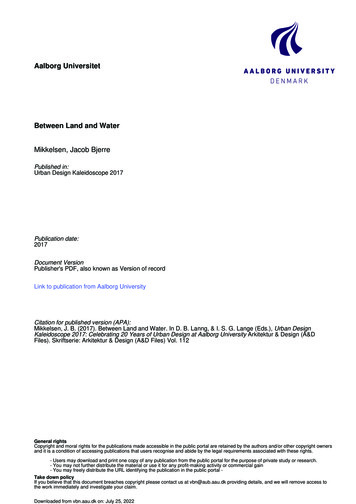
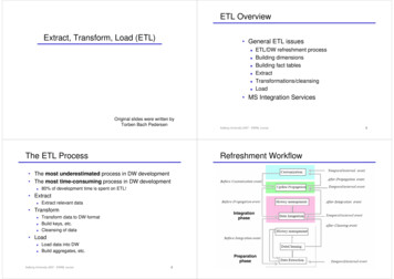
4Over the last several years, researchers have been also working on attaining approval forstandards for the most suitable overall MG design. In [29] a summary of the European andAmerican standards applicable to MGs is presented. The IEEE 1547 and UL 1541 (in the US)standards are the most important guides for operation, design, and connection of distributionresources with electric power systems [13]. Indeed, there are no exact standards which have beendeveloped for adapting MGs, but some Distributed Energy Resource (DER) standards can beadapted to them [29]. IEEE P1547.4 can be adapted for the connection of DERs and specificallyit covers some topics missing from IEEE Std 1547, such as frequency, power quality, and theimpact of voltage [30, 31]. The other standards which can be adapted to MGs to cover lowvoltage distortion and power quality interference are EN50160 and the IEC61000 [32-34].In recent years, several control devices have also been developed for improving theintegration of MGs in island and grid-connection modes. Therefore, the variation of powergeneration and interconnection, as well as the electrical interface between different sources,energy storage, and the main grid may be the barriers for achieving a common standard forconnecting DERs to the grid [29].In order to deal with the above issues, this paper proposes the IEC/ISO 62264 internationalstandard to be applied to MGs and VPP, which are considered here from hierarchical control,energy storage, and marketing perspectives. The objective of IEC/ISO 62264 is to offerconsistent terminology for supplier and manufacturer communications, and to thus serve as afoundation for clarifying applications and information. The standard can be explained at fivelevels: level zero (the generation process), level one (the process of sensing and adjustinggeneration), level two (monitoring and supervising), level three (maintaining and optimizing),and level four (market structure and business model) [35, 36]. Fig. 1 illustrates the adaptation of
5the standards to MGs. The present paper includes a comprehensive literature survey to provideinformation on the detailed status of advances in MG principles from the viewpoints of bothisland and grid connected mode of operation, on the basis of the proposed standard. The MGcontrol hierarchy is discussed in Section 2. Energy storage issues and the microgrid marketstructure are discussed in Sections 3 and 4, respectively. The virtual power plant hierarchicalcontrols are discussed in section 5. The literature survey concludes in Section 6.2. MICROGRID CONTROL PRINCIPLEAs a result of the recent widespread application of power-electronics devices [37], theoperation of an MG requires both energy management and the classification of a control strategy.Power flow control, resynchronization between the MG and the main grid, adjustments ofvoltage and frequency in both modes, and improvements to MG efficiency together comprise thekey principles of MG control structure [38, 39]. The Union for the Coordination of Transmissionof Electricity (UCTE) in continental Europe has defined a hierarchical control for large powersystems, presented in [36]. The most suitable control design should certainly cover all theresponsibilities of MG controllers, which [40] defined thus: the system should function atpredefined operating points, or within satisfactory operating limits; active and reactive powermust be transferred by optimal means; system stability should be maintained; processes ofdisconnection and reconnection should run seamlessly; local Micro sources (MS) productionshould be optimized for best market participation and power exchanges with the utility; loadsmust be classified according to sensitivity, from highest to lowest (e.g. medical equipment is thehighest priority consumer); if a general failure occurs, the MG should be able to operate througha black start; and finally, ESS should support the MG and increase the system’s reliability and
6efficiency. J.J. Justo et al. [41] investigate some different energy management and controlstrategies of the MG system which are published relying on the most current research works.With respect to the above-mentioned requirement, and based on the IEC/ISO 62264 standard,microgrid hierarchical controls are defined on four levels (zero to three), which also are shown inFig. 1. Level zero is the inner control loop for controlling the output voltage and current from thesources. The reference value for the inner control loop is generated by primary control (levelone). Then, secondary control in the next step monitors and supervises the system with differentmethods. Finally, the last level is tertiary control which manages the power follow and interfacebetween the MG and main network. In the rest of this paper, the four levels above the controllevel are discussed.2.1 Internal Control LoopThe target of this control level (level zero of the IE/ISO 62264 std.) is to manage the power ofMSs. Generally, the first step of the MG control is the source operating point control, usingpower electronic devices in current or voltage control modes [38]. The purpose of the powerelectronic interface in voltage control mode is to manage frequency and voltage inside themicrogrid while the system is connected to energy storage devices (island mode) [42]. On theother hand, in current control mode, where the system is often joined to the main grid (gridconnection mode) [43], management of the active and reactive power is the main target [36, 44].Indeed, the inner control loop for wind and solar power which are most common RenewableEnergy Sources (RESs), is in practice created by the power converter. For instance, a DoublyFed Induction-Generator (DFIG) wind turbine consists of two AC/DC (rotor side) and DC/AC(grid side) converters with a DC-link that can either inject or absorb power from the grid,actively controlling voltage [45]. The responsibility of the rotor side is to optimize power
7generation from the source, while providing control of active and reactive power and maintainingthe DC link voltage is the duty of the grid-side converter [46-49]. Moreover, based on thehardware structure of the PV system, after the PV module and MPPT, the system includes dc–dcconverters and inverters, whose responsibility is to create the optimum conditions to support thenormal customer load in island mode, or to send power into the network in grid-connection mode[49].The optimization and inner controls need to have accurate reference values for the frequencyand voltage amplitude, and this is the duty of the primary control.2.2 Primary ControlAs aforementioned, the target of this control level (level one of IEC/ISO 62264 std.) is toadjust the frequency and amplitude of the voltage references that are fed to the inner current andvoltage control loops. The primary control should have the fastest response to any variation inthe sources or the demand (on the order of milliseconds) [50], which can help to increase thepower system stability. Furthermore, the primary control can be used to balance energy betweenthe DG units and the energy storage elements, such as batteries. In this situation, depending onthe batteries’ state of charge (SoC), the contribution of active power can be adjusted in line withthe availability of energy from each DG unit [51]. In other words, to achieve optimalperformance of the primary control, especially in island mode, it is necessary to control the SoC[52]—an idea that will be developed further in section 4. A complete and extensive review andtechnical investigation into the control strategy and hierarchy is provided by Guerrero et al. [53]and Bidram and Davoudi [38].The DG power converter control techniques in ac MGs are classified into two differentmethods: grid-following and grid-forming [54, 55]. Grid-forming converters are voltage-control
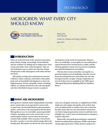
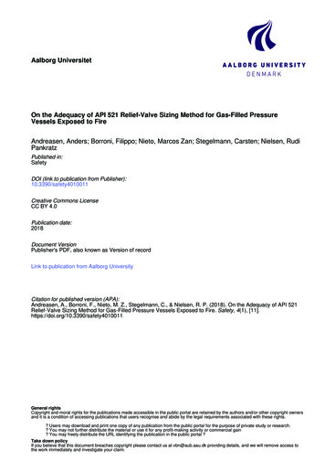
8based and an equivalent circuit for them includes a voltage source and series low impedance.Creating a reference value for voltage and frequency by using a proper control loop is the duty ofthis type of power converter [54]. On the other hand, grid-following power converters aredesigned as control-based and can be represented by a current source with high parallelimpedance. In addition, power delivery to the main network in grid-connection mode is theresponsibility of the grid-following power converter [56]. It should be noted here that one of thepower converters in island mode must be of the grid-forming model in order to determine thevoltage reference value. In other words, a grid-following converter cannot control the MG inisland mode. The differences between these connections are shown in Fig. 2. A comprehensivereview of primary control in grid-forming strategies is presented by T.L. Vandoorn et al. [57];grid-following techniques are discussed by J. Rocabert et al. [58] and F. Blaabjerg et al. [49].2.2.1 Droop Control & Active load sharingThe main idea of the primary control level is to mimic the behavior of a synchronousgenerator by reducing the frequency when the active power increases [59]. This principle can beapplied to Voltage Source Converters (VSCs) by employing the well-known P/Q droop method[60]. The principle of the droop control method for MGs is the same as that for an equivalentcircuit of a VSC connected to an AC bus (Fig. 2) [38]. On the other hand, the principle of activeload sharing involves using a parallel converter configuration based on a communication link[61, 62]. The accretion of voltage regulation and power sharing in the control methods based ona communication link is better than with droop control methods. However, over long distances,communication lines are vulnerable and expensive [57]. There are some different methods basedon communication links which researchers have proposed, such as concentrated control [63, 64],
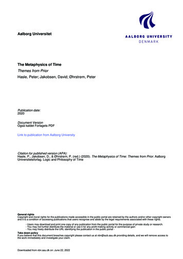
9master/slave [65, 66], instantaneous current sharing [67, 68], and circular chain control methods[69].Since a communication link is not necessary for droop control, it is more reliable than activeload sharing, However, the method does have certain drawbacks [53, 70, 71]: it is onedimensional and can only support one control objective; In an LV distribution line, there isresistive effective impedance between the power electronic devices and the AC bus, so the phasedifference is zero, meaning that it is not possible to apply the frequency and voltage droopcharacteristics to determine the desired voltage references; since voltage in MGs is not found tothe same exact degree as frequency, reactive power control may negatively affect the voltageadjustment for critical loads; the conventional droop method cannot differentiate between loadcurrent harmonics and circulating current in nonlinear loads; and the droop method has its loaddependent frequency and amplitude deviations. A number of researchers have attempted topropose different solutions to these issues, such as load sharing and voltage and frequencyregulation tradeoffs [57], line impedance [72], virtual frame transformation [73-75], couplinginductance [76-78], etc. The ideas are extensively discussed in [38], and [29] along with theiradvantages and disadvantages.The droop is based on voltage-reactive power and frequency-active power controls (P-f, Q-V)in high voltage (HV) and medium voltage (MV) systems, a description of which is given in Fig.3 [79, 80]. The figure illustrates that the operational voltage is regulated by a local voltage setpoint value, taking into account the inductive and capacitive reactive current generated by thesuppliers. In inductive situations, voltage operation increases, and in order to adjust this, thevoltage set-point must decrease. In capacitive mode, however, the set-point value increases. The
10limitations of the reactive current variability are based on the maximum reactive power [40, 81,82].In low voltage (LV) systems, however, the circuit is more resistive and so the droop controlshould be based on active power-voltage and reactive power-frequency (P-V, Q-f ) [73, 83] IfMG sources are to conform to IEEE Standard 1547-2003 [84], then a mechanism should be inplace to restore the system frequency and voltage to nominal values following a load change [85,86]. As in the case of the electrical power system controls, this restoration mechanism is referredto as secondary control of voltage and frequency.2.3 Secondary ControlThe hierarchical control system—in particular, the secondary control section (second level ofIEC/ISO 62264 std.)—works to compensate for voltage and frequency errors and to regulate thevalue in the operational limitations of the microgrid. In other words, the secondary controlensures that the frequency and voltage deviations are regulated toward zero following each loador generation change in the MG. The secondary control serves power systems by correcting thegrid-frequency deviations within allowable limits, for example by 0.1 Hz in Nordel (North ofEurope) or 0.2 Hz in UCTE (Continental Europe) [36]. The response speed of the secondarycontrol is slower than the first control level because of some limitations , such as availability ofprimary sources and battery capacity [58]. This control level can be divided into centralized [87]and decentralized controls [53] . By far the largest body of research and work on decentralizedMG control has been performed by [88]. Additionally, novel general approaches to centralizedcontrol base on droop control and decentralized control based on communication links ispresented by Guerrero et al. [36] and shafiee et al. [89] respectively.
112.3.1 Centralized ControlThe microgrid controllers in centralized control are based on principles similar those of theinner loop controllers explained in the previous part. A Microgrid Central Controller (MGCC) isavailable for each microgrid to interface with the Distribution Management System (DMS).Indeed, the definition of centralization or decentralization is based on the position of the MGCC.This type of control is very suitable for certain small manually controlled MGs, as well as forMGs with common goals and those pursuing cooperation [40].2.3.2 Decentralized ControlThe main duty of decentralized control is to specify the maximum power generated byMSs, while at the same time taking into account the microgrid’s capability to support theconsumer and increasing power exports to the grid for market participation. This type of controlis ideally utilized in the MGs of different suppliers, where there is a need to make decisionsseparately regarding individual situations, and for MGs with active roles in an electrical marketenvironment—such MGs should possess an intelligent control for each unit, in addition to MSswith responsibilities other than power generation [40].In order to connect a MG to the grid, the frequency and voltage of the grid must be measured.These values will serve as references for the secondary control loop. In the case of MG controls,this restoration of references is the duty of the tertiary control. Indeed, the phase angle betweenthe grid and MG will be synchronized by means of a synchronization control loop, which isdisabled in the absence of the grid.2.4 Tertiary ControlThe purpose of this control level (level three of IEC/ISO 62264 std.) is to manage the powerflow by regulating the voltage and frequency when the MG is in grid-connected mode. By
12measuring the P/Q through the PCC, the grid’s active and reactive power may be comparedagainst the desired reference. Hence, grid active power can be controlled by adjusting the MG’sreference frequency. This control level is the last and slowest level of control, and ensuresoptimal operation of the microgrid, not only technically, but also economically [38]. Technically,if a fault or any non-plane islanding issue arises for the MG, then the tertiary control will attemptto absorb P from the grid in such a way that, if the grid is not present, the frequency will begin todecrease. When the expected value is surpassed, the MG will be disconnected from the grid forsafety, and the tertiary control disabled [53]. Islanding detection is also a very important issue indisconnecting the MG from the main grid in tertiary control, and this is discussed in the secondpart of this paper.2.5 Discussion of the hierarchical control of microgridsAdvanced microgrid control techniques under the IEC/ISO 62264 standard are summarizedby the flowchart in Fig. 4. As discussed in this section, and based on the proposed standard, toachieve the optimum level of adjustment of the operational reference value, the control of theMG can be divided into four different levels. The foundational control level is the inner controlloop: active and reactive power management inside the sources and control of voltage in the DClink are its responsibility. Additionally, the inner control loop is implemented by fast voltage andcurrent control loops. An accurate reference value for voltage and frequency for control of thepower converters can be obtained through primary control by different methods. In the next step,there are two different approaches to secondary control: grid connection and island mode. Duringgrid-connection mode, the microgrid operates based on active and reactive power controls,whereas in island operation, the secondary control acts as voltage and frequency based. Asshown in Fig. 4, the reference value for sending the deviation of voltage and frequency to the
13primary control are determined basing on the variation of active and reactive power receivedfrom the main network. Power management and the reinstatement of the secondary control is theobjective of the tertiary control level. Moreover, optimizing the set-point operation of the systemfrom both technical and economic points view is the other objective of the last level of control inthe MG.3. PRINCIPLE OF THE ENERGY STORAGE SYSTEMManaging power balance and stability is a challenging task, as these depend on a numberof variables. Energy storage plays a crucial role in mitigating the problem [8]. In fact, bycombining energy storage with renewable power generators, output power may be stabilized bystoring surplus energy during periods of high obtainability, and dispatching it in case of powershortage [90]. As mentioned earlier in this paper, the principles of MG are almost the same inboth island and grid-connection modes. There are, however, some fundamental contradictionsbetween the two modes in terms of storage systems. Frequency regulation, the integration withrenewable energy production, and the large capacity for power density and energy are the mainapplications of a storage system in grid-connection mode. However, enhancing power quality,stability, and quick response times to transient faults are the main responsibilities of a storagesystem when the microgrid is working in island mode [91]. Another classification of energystorage in the microgrid is based on the arrangement of the storage system, which may beaggregated or distributed. The aggregated model has the same principles as the master unit, andthe microgrid is supported with a central energy-storage system that, depending on the microgridarrangement can be connected to the DC bus or may combine with a power electronic interfaceand connect to the AC bus [92]. This model is very popular for MGs with small scale and lowlevel generation and demand. On the other hand, in the distributed arrangement, the energy
14storage system is connected to the renewable energy sources via different and individual powerelectronic interfaces. In this model, each storage system has responsibility for the control andoptimization of the power output of the sources to which it is connected. The intercommunity ofthe transmission line in the power trade-off between energy storage and MG is a disadvantage ofthe system. [93, 94]One objective of this paper is to adapt the energy storage systems in MG to IEC/ISO 62264standards, which is discussed as below along with a briefly investigating on the differentapplications and techniques of storage systems in MG.3.1 Application of energy storage in microgridAn ESS functions like a power-quality regulator in order to yield a specified active orreactive power to customers. The principle of voltage control, which classifies loads by priorityand employs load shedding, is not suitable for achieving high power quality impact in a MG.Hence, another benefit of ESSs may be that they result in improved power quality in the MG [95,96]. Moreover, there are different applications that can be provided with energy storage systems,such as black start [97, 98], power oscillation damping [99, 100], grid inertial response [101],wind power gradient reduction [102], peak shaving [103, 104], and load following [105]. A.Rabiee et al. [106] present a comprehensive review of these applications with wind turbines.Researchers have also recently been endeavoring to come up with various techniques forimproving power management and system stabilization of MGs by using ESS. Microgrid storagesystems and the power electronic interfaces for linking sources are discussed in [107]. In [108],MG cooperative control methods for island operation are discussed with respect to control overfrequency and voltage, as is a control system for decreasing power variation from RESs (such aswind turbines). ESS can also help to stabilize frequency in very large power systems. The
15influence of electromechanical oscillations on the rapid response of energy storage in a powersystem is indicated by P. Mercier, et al [109] and A. R. Kim, et al [110].3.2 Standardization of energy storage systemAccording to the IEC/ISO 62264 standard, MG hierarchical control configuration falls intothe three categories described previously. As the third level is labeled as a connection element inthe main grid, and the storage system is based on island mode, storage control does not containtertiary controls, but rather consists of a secondary and primary level. The secondary level is thecentralized control, referred to as the master unit or Microgrid Management System (MMS)[111], and like the control hierarchy, the primary level consists of a local control. Primarycontrol monitors the frequency and determines the surplus or shortage of power. Supervisorycontrol of MS and ESS is the responsibility of the secondary control level [112]. Fig. 5 shows thehierarchical control of energy storage [108]. Owing to its quick response to fluctuations, energystorage is a significant element in MGs, particularly in island mode. Sustaining the MG’sfrequency and voltage through a storage system takes milliseconds, while the response times ofdiesel generators, fuel cells, or gas engines is very slow in comparison.Just like the main responsibility mentioned in the preceding section, power balancing for theregulation of frequency and voltage in a storage element of an island-mode MG is also related tothe control level. Nevertheless, due to restrictions in establishing equilibrium between generatedand consumed power as a result of the system capacity on hand, the storage system’s outputpower must be returned to zero as quickly as possible, and this is the duty of the secondarycontrol. [108]
163.2.1 Primary Control in Energy Storage SystemsControlling the active power in the MG is the responsibility of the storage system, whichmust monitor it continually. Based on the first level of the IEC/ISO 62264 s
Microgrids and virtual power plants (VPPs) are two LV distribution network concepts that can participate in active network management of a smart grid [1]. With the current growing demand for electrical energy [2], there is an increasing use of small-scale power sources to support specific groups of electrical loads [3].