Transcription
t'.liJMSX Technical DataBookHardware/Software SpecificationsPresented byRobs /s MSX Worksho Originaly scanned byIvan LatorreConverted to PDFEduardo Robsy[September 2004]SONY.
MSX Technical DataBookHardware/Software SpecificationsSONY.
Sony Corporation4 14 1, Asahi-cho, Atsugi-shi,Kanagawa-ken, 243 JapanCopyright t :' 1984 Microsoft CorporationProduced by ASCII CorporationPrinted inJapan
PREFACEThe Microsoft MSX standard was i nv ented to provide end usersand software dev elopers with a standardiz ed computer so thatprograms could run on a ny computer even though they wer e made byd i f f er ent manufacturers.Thi s book pr esents the MSX s pe c i f ications in detai l .It isi ntended to be a ref er ence for adv a nced prog r ammers and softwaredev eloper s .The i nformation is generally divided four parts.Part A,MSX H ARDWARE SPECI FICATIONS,for the MSX system hardwar e.pr esents the specificationsChapter 1 ,Hardwar e Specif ica t i o n, cov er s the MSX sta ndardhardware conf iguration i n terms of the r eq u i r em ents for the LSis,i nt er r upts,m emory siz e,scr een, keyboard, and sound used i n themai n uni t ; a nd the various (cassette, fl oppy , pr i nt er , serial , andi nt erfaces and co nnectors.It also covers topics such asslot cartridges, expa nsion, ports, a nd m emory maps.MS X SYSTEM SOFTWARE,contains a r ef er ence guide for MSX Part B,BAS IC a nd i nformation for adva nced programmi ng .Chapter 2 ,Language Specification,i s a guide to MSX-BAS I Ca nd is for use with advanced programming r eq u i r i ng machine l a n guage routi nes.is about the advanced f ea Par t C,EXPANDED MSX SYSTEM SOFTWARE,tur es of MSX, includi ng Expa nded Disk B AS I C and MSX-DOS.Chapter 3 , MSX-DOS,co ntai ns a us er ' s guide to MSX-DOS andthe adva ncedand i ncludes i nformation needed forDisk BASIC,programmer .Chapter 4,Other Expa nsion,covers the serial (RS-232C)pans i o n and B IOS call s availabl e i n the extended version.Part D, SOFTWARE DEVELOPMENT GUIDE,ware developers.ex contains informati o n for soft Chapt er 5,I nternational MSX V ersions a nd their Diff er ences,is for manufacturers or programmers who w i sh to make the hardwareor softwar e be usable i nt er nationally.containsNotes for MSX Software Dev el oper s,Chapter 6 ,whensoftware dev elopers shoul d considerthati nf o rmationprogramming for MSX computers.
Syntax Notation i n Reference SectionsWherever the format f or a statement/command or a function is given,the following rules apply :CAPSItems in capital letters must be input as shown. Items in lowercase letters enclosed in angle brackets are to be suppl ied by the user.(1Items in square brackets ( [ l) are optional .{.may be repeatedI tems followed by an ellipsis ( number of times (up to the length of the l ine ) .}anyBraces indicate that the user has a choice between two ormore entries.At least one of the entries enclosed i nbraces must be chosen unless the ent ries are also enclosedin square brackets.At leastvertical bars separate the choices within braces.one of the entries separ ated by bars must be chosen unlessthe entries are also enclosed in square brackets.All punctuation except angle brackets and squarebrackets( i. e. , commas,parentheses ,semicolons,hyphens, equal signs must be included where shown.Arguments to functions are always enclosed in parentheses.In thethe arguments areformats given for the functions in this book,abbrev iated as f ol l ow s :X and YRepresent any numer i c expressions.IRepr esent integer expr essions.and JX and Y Represent string expressions.2
C O N T E N T SPART A1.MSX HAROOARE SPECIFICATIONSHardwa-re S pecif !cations1 . 1 MSX Standar d 8.1 . 2 Y X System Conf iguration 9.1 . 3 Main Unit .10. .1 .3 . 1LSis. . 10.1 .3 . 2 Memory . . . . 10.1 . 3 . 3 Interrupts .11. . . . . . . 1 . 3 . 4 Screen . . 121 . 3 . 5 Keyboard.13. .1 . 3 .6Sound.14. . . .1 . 4 Interfaces. . . .15. .1 . 4 . 1 Cassette Interface151 . 4 . 2 Floppy Disk Interface.181 . 4 . 3 Printer Interf ace191 . 4 . 4 RS-232C Interf ace. . . 201 . 4 . 5 Peripheral I/O Por t ( s ) 25.1 . 4 . 6 Joysticks. 271 . 4 .7 Paddles 2 81 . 4 . 8 Connectors.29 1 .4 . 9Slots . .301 . 5 Cartridges . . . . . . 31 311 .5 . 1 Cartr idge Standa r d.321 . 5 . 2 Cartr idge Bus. . . 341 . 5 . 3 Cartr idge Bus Connenction Condi tions 3 41 . 5 . 4 Car tridge Power Capacity . . . . . . . . . . . . . . . . . . .1 . 5 . 5 S ampl e Circuit Diagram of Expanded Slot Select Signal3 51 . 6 Notes for System Expansion . 36 I I I e1 . 6 . 1 RAM Expansion 36. .1 . 6 . 2 Slot Expansion. . 36.1.6.3I/0 Expansion 371 . 7 Address Maps . .381 . 7 . 1 Memory Map 3 81 .7 .2I/0 Address Map 401 .7 . 3 Printer Port 41.1 .7 .4 VDP Po rt. 41l . 7 5 PSG Po r t. 41.l . 7 . 6 PPI Port. . . . . . . . . . . . 41. .1 .7 . 7. . . . . . . . 41. . .External Memory ( SONY). . . . . 411 . 7 . 8 L ight Pen ( SANYO ) . . . . . 421 .7 . 9 Audio/Video Control421 . 7 . 1 0 Notes on I/O Address Assi gnments. 431 . 7 . 1 1 8255 (PPI Bit Assi gnments. 441 . 7 . 12 PSG B i t Assignments . . . Ie PART B2. MSX SYSTEM SOFTWARELanguage Specifications2 . 1 MSX B AS IC Reference Guide 2 . 1 . 1 Modes of Operation 3. .46. . 46
2 . 1 . 2 Line Format . . . . . . . . . . . 472 .1 . 3 Character Set . . . . . . 472 . 1 . 4 Constants . . . . . . . . . . . . . . . . . . . . . . . . . . . . . . . . . . . . . . . . . 4 82 . 1 . 5 Var iabl e s . . . . . . . . . . . . . . . . . . . . . . . . . . . . . . . . . . . . . . . . . 502 . 1 . 6 'I'i'pe- Conversion . . . . . . . . . . . . . . . . . . . . . . . . . . . . . . . . . . . . 51Expressions and Operators . . . . . . . 532.1.72 . 1 . 8 Program. Editing . . . . . . . . . . . . . . . . . . . . . . . . . . . . . . . . . . . . 572 . 1 . 9 Special Keys . . . . . . . . . . . . . . . . . . . . . . . . . . . . . . . . . . . . . . . 6 22 . 1 . 1 0 Error Messages . . . . . . . . 632 . 1 . 1 1 Commands and Statements except those doing I/0 . . . . 632 . 1 . 1 2 Functions except those doing I/O . . . . . . 7 92 . 1 .13 Device Speci f ic statements . . . . . . . . . . . 842 . 1 . 1 4 I/O Functions . . . . . . . . . . . . 1 002 . 1 . 1 5 Special Variables . . . . . . . . . . . . . . . . . . . . . . . . . . . . . . . 1 0 22 .1 . 16 Machine Dependent Statements and Functions 1 042 . 1 . 1 7 Summary of Error Codes and Messages . . . 1 052 . 1 . 1 8 MSX BASIC Reserved words . . . . . 1 0 92 . 2 Advanced Programming Guide . . . . . . . 1 1 02 . 2 . 1 BIOS Entry List 1 1 02 . 2 . 2 Work Area . . . . . . . . . . . . . . . . . . . . . . . . . . . . . . . . . . . . . . . . 1 3 52 . 2 . 3 Slot Cont r ol . . . . . . . . . . . . . . . . . . . . . . . . . . . . . . . . . . 1 6 12 . 2 . 4 Cassette I/O Mechanism . . . . . . 1722 . 2 .5 MSX Printer Specifications . . . . . . 177. .PART C3.EXPANDED MSX SYSTEM SOFTWAREMSX-DOS3 .1 MSX-DOS User's Guide . . . 1 82Sy stern Requirements . . . . . . . . 1 823 .1 .13 . 1 . 2 Getting Started . . . . . . . . . . . . . . . . . . . . . . . . . . . . . . . . . . . 1 823 . 1 . 3 Wild Cards . . . . . . . . . . . . . . . . . . . . . . . . . 1 84. . . .3 . 1 . 4 Ill egal File Names . . . . . . . . . . . . 1 853 . 1 .5 Directories . . . . . . . 1 863 . 1 . 6 Types of MSX-DOS Commands . . . . 1 863 . 1 . 7 Command Options . . . . . . . . . . . . . . . . . . . . . . . . . . . . . . . . 1 873 . 1 . 8 Information Common to All MSX-DOS Commands 1 8 83 . 1 . 9 Batch Processing . . . . . . . . . . . . . . 1 893 .1 .1 0 The AUTO EXEC. BAT F i l e . . 1 903 . 1. 1 1 How to Create a Batch File . . . . . . . . 1 913 . 1 . 1 2 Replaceabl e Parameters i n .BAT Fil e . . . . . . . . . 1 923 . 1 . 1 3 MSX-DOS Editing and Function Keys . . . . . . . 1943 . 1 . 1 4 Instructions for Users with Single-drive Systems 2 003 . 1 . 1 5 Disk Errors . . . . . . . . . . . . . 2013 . 2 MSX-DOS Command Guide . . . . . . . . . . 2 0 23 . 3 MSX Disk BASIC Reference Guide . . . . . . . 2 1 93 . 3 . 1 Commands and Statements . . . . . . 2 1 93 . 3 . 2 Fun ct ions . . . . . . . . . . . . . . . . . . . . . . . . . . . . . . . . . . . . . . . . 2 463 . 3 . 3 Error Codes and Error Messages . . . . . . . 2 5 23 . 4 MSX-DOS and Disk BASIC Boot Procedure . 2 553 . 5 MSX -DOS and Disk BASIC Disk Drivers . . 2 5 63 . 6 MSX-DOS System Calls . . . . . . . . . . . . . . . 267.4.
4.Other Expansion4 . 1 MSX-RS23 2C Suppo r t . . . 2 904.1.1Extended BASIC for RS-2 3 2C Commun i cation . . . . . . 2 914 . 1 .2Extended B IOS cal l s Handling RS-232C . . 3 0 04 . 2 Other MSX Extended B IOS Calls . . . . . 3 0 94 . 2 .1Extended B IOS Cal l s . . . . . . . . . 3 0 94 . 2 .2Extended B IOS Maker I D Number . . . . . . . . 3 1 3Tenkey Suppo r t on MSX . . . . 3 1 44.3PART Ds.SOFTWARE DEVELOPMENT GUIDEInternational MSX versions and their Differences5.1Introduction . . . . . . . . . . . . . . . ,., . . . . . . . . . . . . . . . . . . . . . . . 3 1 65 . 2 Keyboard3165 . 2 .1Keyboard H a r dware . . . . . . . . . . . . . 3 1 65 . 2 . 2 Character S e t . . . . . . . . . . . 3 1 75 . 2 . 3 Keyboard Layout3195 .2 .4CAPS Lock . . . . . . . . . . . . . . . . . . . 3 1 95 . 2 . 5 DEAD-Key Functions . . . . . . . 3 3 1Screen Mode . . . . . . . . . . . . . . . . . . . . . . . . . . . . . . . . . . . . . . . . . . 3 3 35. 35 . 4 Other Differences among Versions . . . . . . . . . 3 3 45 .5ID Bytes . . . . . . . . . . . . . . . . . . . . . . . . . . . . . . . . . . . . . . . . . . . . . . 3 3 5.6. . . . . . . Notes for MSX Software Devel oper s5 . . . . . 336
6
PART AMSX HARDWARE SPECIFICATIONS
MSX HARDWARE SPECIFI CATIONS1 . Hardwar e Specificat i ons1.1MSX Standardo CPUZ80A compatibleo MEMORYROM:RAM:32K bytes CMSX system softwar e)16K bytes (Minimum o SCREEN DISPLAYText displ ay :G r aphics :Color s :32 x 24( See Section 2 . 4 )256 X 19216o CASSETTE TAPEFSK format, 1 2 0 0 / 2 4 0 0 B audo SOUND8 Octaves, 3 Voiceso KEYBOARD V ERSIONSAlphanum erics, Japanese, G r aphicsAlphanumerics, European, G r aphics( J apanese)( I nter national )o FLOPPY DISK DRIVESH ardware depends on the manufactur erDisk format MS-DOS-compatibleo PRINTER *8 bit pa r allelo ROM CARTRIDGE AND I/0 BUSSoftware cartr idge and expansion BUS slotso JOYSTICKS *1 or 2o CHI NESE CHARACTERS *At manuf acturer ' s disgression* The items with asteriskssystem configur ation.may not8beprovidedinthe basic
MS X HAR'DIIAR E SPECIFI CATIONS1.2MSX System Conf igurationo MINIMUM CONFIGURATIONSOUND OUTPUTCARTRIDGE SLOTV IDEO OUTPUT1ROM 32KRAM 16KPPIZBOAPSGVDP-IKEYBOARDCASSETTEJIJOYSTICKX 1o SOFTWARE SUPPORT LIMITSOUND OUTPUTV IDEOOUTPUTtZBOAPSGVDPPRINTEROUTPUT1CARTRIDGESLOTS x 1 5ROM 32KPPIRAM 32K for BASIC6 4 K for DOSKEYBOARDCASSETTEJOYSTICKX 29x1
MSX HARI:MARE SPECIFICATIONSMain Unit1.31.3.10CPU0VDP0PSG0PPI1.3 .2o ROMo RAMLSisZ 60 A compatibl eClock 3 . 5 7 95 45MHz ( NTSC Color sub-ca r r i er f requency)1 WAIT in Ml CYCLET I TMS-991 6A compatibleG I AY-3-8910 compatibl eI nt el i- 8255 compatibl eMemoryMSX-BASIC, 3 2K bytesMinimum 16K bytesNOTEsystemtheminimumSinceconf igurationcontains fourslots,the m emory ar ea may beexpanded up to 2 56 K by tes.Eachslot can bef u r therexpanded to have four slots,for a total of 16 slots.Thusthe maximum memory space is 1megabyte.BAS I C ROMTheinterpr eteroccupiesaddresses 0 0 0 0 to7FFF,and the RAM addressesstart at FFFF and grows down ward on the memory map.See the memory map in1 . 7 for details.10Section
MSX HARDWARE SPECIFICATIONS1 .3 .3oInter r uptsNMINot used.o!NTMSX ROM only provides a RAM hook.the VDP and the cartridges.Interrupts a r e accepted f r omThe interrupt mode is 1.( Branchto 3 8 8)The MSX sy stemsoftware uses an int e r r upt f r omthe VDP.The interruptintervals a r e 6 0 Hz in the NTSC versionand 50 Hzin thePAL/ SECAM version.Z80VDPNOTEIt is not possible tosuppo r tNMIunder MSX-DOS because theaddress66H(an entry vectorfor the NMI) isusedbytheMSX-DOS FCB data.11
MSX HARDWARE SPECIFICATIONS1 .3 . 4ScreenoLSIoCharacter setAlphanumerics Japanese ( E uropean) Graphics256 patterns, 8 x 8 dotsoColoroSprites3 2 sprites,withhoriz ontal l ine .oDisplay modesT I TMS9 918A Compatible1 6 colorsa maximum of four spr ites onthe samer-----------------y-------T------T---- -----y------ T------,IIMODEII RES.I NO. II SPRITE I NO. OF II* ! COLOR I AVAIL. !CHARS. II SIZE It-------y--------- ------- ------ ---- ------ ------ ------ LSII 256IIIIIIII 32x24 1I Graphic ISpec.I xl92III16I -------- ------- 8 x 81 256 l color s l Yes ------ IIII Suggested I 240IIIIIIIIvalueIII 2 9X 2 4 III x1 9 2I ------- ------ -- - - -- - --- ------ ---- ------ --- --- ------ IIILSII 256IIIIII 32x241II Graphic ISpec.III16I xl92 -------- ------- 8 x 81 76 8 l color s l Yes ---- -- IIII! Suggested! 240IIIIIIIIIII 29X24 1IvalueI xl92II ------- --------- ------- ------ ---- ------ ------ ------,IILSII 64III Multi-1Spec.I x48blklII color r--------- ------- 4 x 4 1II /Block II Suggested I 64IIvalueI x40bl k lIIII16I- lcolor s l YesIIIIIII32x241t------iIII 29x24 1 ------ --------- ------- ------ ---- ------ ------ ------ IIIIIIILSII 256IIIISpec.I xl92III2IText r----- - --- ------ - , 8 x 6 1 2561out of l NoI Suggested I 240III16IIvalueI xl93IIl colors lIII 40x24 1 ------iIII 39x24 1 ------ -------- ------ ----- --- ----- ------. ----- *Number of patternsSuggestedvaluesThe eight pixels f r om the left and right of thehoriz ontal l ine a r e not used by the software.12
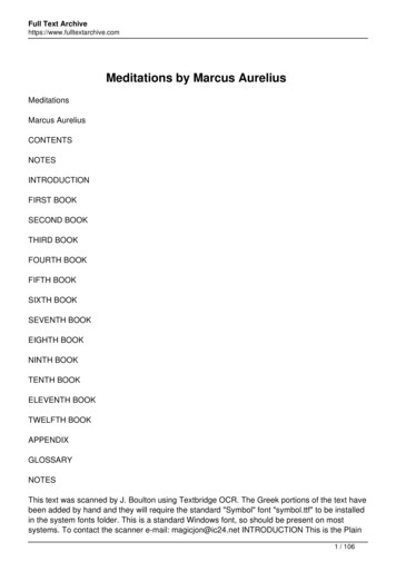
MS X HARDWARE SPECIFICATIONS1.3.5Keyboar do LayoutAlphanwner icsJapanese syllablesEuropeanGraphic Characters: ASCII standardJ IS standard syllable layout: Internati onal ver sionsDepending on international version(Selected by jumper connection)o ScanningSoftware scanning driven by VDP interrupto Number of keys72See section 5 . 2 .2/ 5 . 2 . 3 for details.o Matrix diagramPBO t-PBl PB2PB3PB4PBSPB6PB7PCO t-- APCl t-- BPC2 r------ cPC3 t-- DYO0123 I ['-'4 ,.5678910r-p---p-Jx7 lx67X5X3X4xoXlX26543210/'-.-98Yl.'(@ Y28A * -/Y3JIHGFEDcRQp0NMLKzyXwvuTsF3F2FlKANACAPJY5 Y7Y8RETURN SUECT J).'(* *)STOPTABESCil' DELINSYlO* Unde r score character.**Code Lock key in international versions.13GRAPH CTRLBSyg)F5.SHIFTF4HOME SPACE
MS X HARDWARE SPECIFI CATIONS1.3.6SoundoLSIoOCTAVES8 Octaves ( 3 Voice s oSOUND EFFECTSAvailableoSOFTWARE SOUND OUTPUT1 bit f rom output portoOUTPUT LEVEL- Sdbm (Providing the system has an output connect o r oOONNECTORRCA 2 pinsGI AY-3 - 8910 Compatibl e . Clock 1 . 7 897725 MHz ( 1/ 2 CPU clock)(Prov iding the system has an output connector)14
MSX H ARDWARE SPECIFI CATIONS1.41.4.1InterfacesCassette Interfaceo INPU TFrom the earphone terminal of the tape recordero OUTPUTTo the micr ophone terminal of the tape recordero SYNCHRON IZATIONAsynchronous, software-controlledo B AUD RATES1 2 0 0 baud ( 12 0 0Hz - 1 wave " 0 " ,n 1 " ) (Default)2 4 0 0 Hz2waves2400 baud ( 24 0 0 Hz1 wave " 0 " , 4 8 0 0 Hz - 2 waves" 1" ) , software-selected(The tape recorder to be used may have to be speci fied by the manufacturer when using 2400 baud)o MODULATIONFSK (Frequency Shift Key ing) , software-controlledo DEMODULATIONSoftware-controlled.The system software automaticallydetects the baud rate upon receiving the data.o MOTOR CONTROLAvailableo CONNECTORDIN 45326( 8 pins)15
MSX H ARDWARE SPECIFICATIONSo TABLE OF S IG NAL -------------,IIPIN INO. ISIGNALNAMEIII DIRECTION IP I N CONNECTION ----- ---------- --------- ------------------------------- G 1·----- ---------- --------- II2IIIIIGNDI ----- ---------- --------- II3IIIIGNDII ----- ---------- ---------iII4IIIICMTOUTIOUTPUTI ---- - - --- ----- - -------- II5II6II7II8II CMTINII INPUTII ---- ---------- ---------iII REMOTE I OUTPUTIIIIII·----- ---------- ---------;REMOTE-II OUTPUTI·----- ---------- ---------iIIGNDIIII -----. . 16
MSX H ARIMARE SPECIFICATIONSoSAVE LevelThe constants in the SAV E circuit ahoul d be adjusted so as toperform the output l evel as follow s :Output l evel-45 dBm 5 dBm( 0 dBm 0. 77 5 V)The output should be 2 2 rnV p-p - 7 rnVp-p at 1 2 0 0 Hz input signal Sampl e Circuit for SAVEJC---ilp FOutput to GMT 7kQStandard Value ( *)0Freq uency Characteristics4.7knI0.022pFlOOQ6dB/oct6dB/octMIN 16HzMAX200Hz3kHzLower Cutoff Frequency ( *)*Higher Cutoff FrequencyNote that the lower cutoff capacitor i s to protect the IC o f MSX.Cassette tape recorders themselves will not be harmed even ifit i s not there. The capacitance may be i n the range 0 . 1 - 2 . 2 F.Adj ust the capacitor to l imit the lower cutoff f req uency in therange 1 6 - 2 0 0 Hz , if the output inpedance of the IC is too high.17
MSXHARDtlARE SPECIFICATIONS1 . 4 .2oFl oppy Disk InterfaceThe Floppy Disk Interface contains 16K bytes ofat 4 0 0 0 H that includes the following modules :***MSX-DOS KERNELMSX DISK BASICPHYS ICAL DISK I/0 DRIVERROMbeginning( Suppl ied by manufact urer )oThe hardware interface is not specif ied.I/Odriver suppl ied by the manufact urerhardware differ ence s.oIdeally, the mechanism in the disk drive should detect that thedrive door has been opened.This reduces the number of diskaccesses r eq uired to check i f the system disk been replaced.0Floppy disk format:The phy sical diskshould resolve theMS-DOS compatible8- inchSingle-density1 2 8 Byte s/Sector8-inchDouble-density1 0 2 4 Bytes/ Sector5 . 25 - inchDoubl e-density512 Bytes/Sector3 . 5- inchCFD512 Bytes/ Sector3 - inchCFD512 Bytes/ Sector18
MSX H DWARE SPECIFICATIONS1 . 4 .3Printer Interfaceo SPECIFICATIONS8 bit parallel, handshakes by BUSY and STROBEo LWELTTLo OIARACTER CODESSame as the MSX di spl ay codeso CONNECTOR1 4-pin AMP compatibleo L IST OF PINSr---- - - - - - - - - - - - - - - y - - - - - - - - - - - - - - - - - - - - - - - - - - - - - - - - - - IIPIN NO.I1II SIGNAL II I/01I NAMEPIN CONNECTION -------- -------- --- ---------------------------------- I 0 III2IPDB OI 0 I1--- ------- -------- ---4IIPSTB --------- ----- --- ----1I3IPDBlIIIII 0 I1---------- -------- ----1I4IPDB2 I 0 I1---------- -------- --- 5IPDB3I 0 I ,------.I1---------- -------- --- I6IPDB4I 0 I7 ---------- -------- --- I7IPDBS1---------- -------- --- I 0 IIPDB6I 0 I1--- ---- -- - ----- --- ----19IPDB7I 0 III8l6141---------- -------- --- 135124113102918IIIIIIJIIIIIII - III I I1---------- -------- ---112IIN . C.I - I ---------- -------- -- I13II - IN . c.IIIIIIII10IN . c.1--- ------- -------- ---lI11IIBUSY1------- --- -------- ---iI14IGNDI-I --------- J19
MSX HAROO'ARE SPECIFICATIONS1.4.4oRS-2 3 2C InterfaceLSI OJMPONENTSi-8251 Communications Interfacei-8253 Pr ogrammable Interval TimerAt least 4K bytes of ROM i s required for software support.oPORT ADDRESSESSOH81H82H82H83H84H85H86H87 H*RIWRIWRwR/WRIWR/Ww8251 Data Port8251 Command/Status PortStatus Sense Por t for CTS, Timer/Counter 2 , RI, and CDInterrupt Mask RegisterReserved8253 Counter 08253 Counter 18253 Counter 28253 Mode RegisterThe port at address 8 3 H is reserved for use by the manufacturer.20
MSX HARDWARE SPECIFI CATIONSoUSING TH E PORT AT ADDRESS 8 2 H82H Rea d :G e t System --- ,IIDataBitDescription ------- ------------------------------------- IIIIIIIIIJIIIID7D605D403D2DlDOIIIIIJJIIICTS (Cl ear To Send)0:CTS Asserted1:CTS NegatedTimer/Counter Output-2 from i8253--,I--.JReserved RI (Ring Indicator )0:RI AssertedI1 : RI NegatedI CD (Carr ier Detect)I0:CD AssertedI1:CD NegatedIIIIIIIIIIIIII ------- ------------------------------------ NOTE:The signals with the pl us ( ) sign a r e optional.If only one signal is chosen, it must be 'CD'.NOTEThe CTS signal is sensed through the portinstead o f through the 8251 because of aproblem in the CTS logic in some versionsof the 8251 .Software handl ing is thusmade p()ssible.21
MSX HARDiARE SPECIFICATIONS82H Write :Interrupt Mask Register -------- --------------------------------------- ,I DataI BitDescription ------- 302DlDO-- -.II Reserved--.1. Timer Interrupt f rom i8253 channel-21:Mask Interrupt Initial val ue )0 : Enable Interrupt Sync character detect/Break detect1 : Mask Interrupt ( Initial val ue)0 : Enable Inte rrupt Transmit Data Ready ( T x Ready)1 : Mask Interrupt ( I ni t i al val ue)0 : Enabl e Inter r uptReceive Data Ready ( R x Ready)1 : Mask Interrupt ( I nitial val ue)0 : Enable Interrupt -------. --------------------------------------- NOTE :The signals above with the pl us ( ) si.gn a r e optional .The minimum requi rement for the interrupt signal isthus Rx Ready .22
MSXoHARDWARE SPECIFICATIONSUSING 'mE 8253 TO G ENERATE BAUD RATE CLOCK FOR THE 8251A.CRYSTAL FREQUENCYThe crystal freq uency is 1 . 8 4 3 2 MHz. ------------------ -----------------------------,I Baud rate (Baud)I Scale Factor and Error (xl6)Ir------------------ ------------------------------ 50751101503006 0012001 80 02000240036004800720096001 92 0 0230415361 0 477683 84192966458483224161261 1 0 . 0 2 87 0 . 3%1 9 86 . 2-0.7% ----------------- ----------------------------- B.USING THE COUNTER CHANNELCHO :CHl :CH2 :Rx Baud rate clockT x Baud rate clockUsed by appl ication ( I nterrupt generated optionally)23
MSX HARDWARE SPECIFICATIONSoPINS OF DB25 CONNECTORr----- - -----------------, ------- ------------------ IIIIIIIIIIIII12345678910111213I Frame GroundI Transmit DataI Receive DataI Request To SendI Clear To SendI Data Set ReadyI S i gnal GroundI Carrier DetectIIIIISignalI PinSignalI Pinr-------y--------------------,IIIIIIIIIIIII ------- ----------------- 24 ------- -------------------- IIIIIIIIIIIII141516171819202122232425IIIIIII Data Terminal ReadyII Ring IndicatorIIIIL------- -------------------
MSXH ARDWARE SPECIFICATIONS1 .4.5Peripheral I/O Por t ( s )( 1 or 2 *o LSIAY-3-89 1 0 compatibleo I/OInput4bits,Output1bit,Bidirectional2 bits per porto LOG ICActive higho LE.VELTTLo CONNECTOR9-pin AMP compatibleo LIST OF PINSr----- ------- -------- --------------------------------,II PIN I SIGNAL II NO. I NAMEI D IRECTION IPIN CONNECTIONII ---- -------- --------- --------------------------------- II1------ -------- ----------tIII1II2II FWDII InputII BACKIIIIInputIIIIIIIIII ---- -------- ----------tII3I LEFTII nputII ---- -------- ----------tII4II RIGHTII I nputII D @ ---- -------- ---------;II5II* SVIIIII V ---- -------- ---------;III6ITRG 1I I nput/I OutputII ---- -------- --------- .II7II TRG 2IIOutputII1------ -------- ---------iII8IIOUTPUT I OutputIIIII ---- -------- ---------iII9I GNDIII . L- .*Curr ent capacity :SOmAIIIIeach25
MSX HARDWARE SPECIFICATIONSoCircuit DiagramAY·3·8910k·'" U74LS157IOAOlYlA10Al2Y2AIOA23Y3AIOA34Y4A k 5VJ3-'--1828sJ:G384800000000J; 5V74LS157T '--lAIOA4lY2AIOA52Y18 s G!r---2800000000 7407X4/6lOBO 5VlOBI 10821083108410851086 1----All resistors are lOk ohm typically.2623456789J4-,- r- -:- 5V1123456789
MSX HARIMARE SPECIFI CATIONS1 .4 . 6oJoysti cksThere are two types o f j oysticks.Joystick Type A has one trigger button,or if there i s morethan one trigger button, the software cannot distinguish betweenthem.Joystick Type B has two independent trigger buttons.The j oysticks produced f r om now on should show which type theyare and software that needs to have Type B should say so on thepackage.oCircuit DiagramAMP9PINFWD100200LEFT300RIGHT400BACKTRG A600TRG B7 o8Option a s described above. ------ 27
MSX HAR ARE SPECIFI CATIONS1 4 7oPaddlestrigger pulse is sent to the 8 pin of the pe r ipheral I/O po r tevery time the PDL function i s called.The paddle circuit,triggers the monostabl e multivibrator with this pulse.A pulseof the length corresponding to the level of the volume i sreturned to the port.AA maximum of 6 channe l s of paddl espo r t .can be attached to each I/0Paddle timing diagramFWDl s.TA ·-TD j.I.L.r--r----1r lOtLSto----3msCircuit diagram ( for 1 channel )vee5 0150KQVR.8Q1------u 1(2,3,4,6,7)CLRLS 123 or EQUIV.NOTE :The vol ume or the capacitance) should be adjustable a s toj ustify the function of the paddle.28
MSX HARI:MARE SPECIFICATIONS1 .4 . --------------------,PIN NAMESPECIFI CATIONS ---------------------- ---------------------------------- II 1 . Video output andIcomposite videoII 2 . RF modulated signalJIIDIN 5-Pin Connector * ,I RCA 2-Pin ConnectororIl RCA 2-Pin ConnectorIIIIIJI ----------------------- ---------------------------------- IJCassetteII DIN 8-Pin ConnectorIII/O PortII AMP 9-Pin ConnectorIPrinterIIICartridge BusI(DIN-453 2 6 )JI ----------------------- ---------------------------------- II ----------------------- ---------------------------------- IIUNPHENOL14-Pin ConnectorII ---------------- ------- -- -- ---- -- - ------- - --- --------- --- I2 . 5 4 PACE, 5 0-Pin ConnectorIIr----------------------- ---------------------------------- IIIAudioIRCA 2-Pin ConnectorIIL----------------------- ---------------------------------J*DIN 5 -PIN CONNECTOR SIGNAL PIN AS S IGMENTSr-------- ----------- ----------------------------------- I PIN NO. IPIN OONNECTIONNAME -------- ------------ ------------------------------------ II1II SVIIr-------- ------------ II2IIGNDII ------ - - -- -- --- --- --iIIIIAudio4IIMonitorII5IIRF VideoIII3IIIIIr- ------- -- -- -- - -----ir-------- ------------i ------- ----------- -----------------------------------29
MSX HARmARE SPECIFICATIONS1.4.9oSlotsCONCEPT OF SLOTSthe concepts ofFor computers having 64K bytes of memory,slots and memory banking are nearly identical.The CPU candirectl y choose the cartridge by its slot numbe r .The slot concept originated f r om a desire to support the maxi mum amount of software.Using the slots, the software can beregardless of the number of physical slots availabl e torun,the computer.oADVANTAGES OF SLOT STRUcrUREwhen there is an even number ofI n a common bus structure,the dev ice select signal connected to the busmemory banks,cannot distinguish between the different dev ices by using theIf this were to occur, the system would notsame memory area.only be unusabl e, but the hardware would quickly deteriorate.By using the slot select signal to choose the memory devices,the above problem is avoided,and programs that handl e two ormore devices having the same memory area are made possibl e .This is a favorable point, considering the system' s flexibil i ty and expandability.0Circuit diagram8255PAOPAlPA2PA3PA4PA5PA6PA78255Chip A2YBSITSio2COlClSLTSLl2Cl1C22C21C32C3---tA----- 30V2SLTSL2yjSLTSL3
MSX HARIM'ARE SPECIFI CATIONS1 .5Car t r i dges1 . 5 .1Physical Cartridge Specificationso Physicaldimension of the standard cartridgeINSERTDIRECTION (FRONT)0' :-o 0r-,II: lL. ----------------.lI·G\ 1I109:l:::: ; ' J L : o Physical dimension of the expanded cartridgeIJ--T-- I;I- -----'-- 0 . 7109- .:.J -.QI---31L-
MSXHARDWARE SPECIFICATIONS1 .5 . 2Cartr idge Buso LIST OF S IG NAL PINSr------- ------------- ----T-------T-------------- ----,PINNO.NAMEI* II I/0 IPINNO.I* II I/0 1NAME -- - --- ------- - - - ---- ----- ------- -------------- 9CSlCS12Reserved tWAIT%MlIORQWRRESETA9AllA7Al2Al 4A1A3ASD1D3DSD7GNDGND SV 44464850CS2SLTSLRFSHINT%BUSDIRMERQRDReservedAl 5A!OA6ASAl3AOA2A4DOD2D4D6CLOCKSWlSW2 12V-12Vt000II0000000000I/0I/OI/0I/00 -------. ---
Chapter 2, Language Specification, is a guide to MSX-BASIC and is for use with advanced programming requiring machine lan guage routines. Part C, EXPANDED MSX SYSTEM SOFTWARE, is about the advanced fea tures of MSX, including Expanded Disk BASIC and MSX-DOS. Disk Chapter 3, MSX-DOS