Transcription
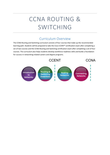
Chapter 1: Routing ConceptsCCNA Routing and SwitchingRouting and Switching Essentials v6.0
Chapter 1 - Sections & Objectives 1.1 Router Initial Configuration Configure a router to route between multiple directly-connected networks. Describe the primary functions and features of a router. Connect devices for a small, routed network. Configure basic settings on a router to route between two directly-connected networks, using CLI. Verify connectivity between two networks that are directly connected to a router. 1.2 Routing Decisions Explain how routers use information in data packets to make forwarding decisions in a small tomedium-sized business network. Explain the encapsulation and de-encapsulation process used by routers when switching packetsbetween interfaces. Explain the path determination function of a router. 2016 Cisco and/or its affiliates. All rights reserved. Cisco Confidential2
Chapter 1 - Sections & Objectives 1.3 Router Operation Explain how a router learns about remote networks when operating in a small to medium-sizedbusiness network. Explain routing table entries for directly connected networks. Explain how a router builds a routing table of directly connected networks. Explain how a router builds a routing table using static routes. Explain how a router builds a routing table using a dynamic routing protocol. 2016 Cisco and/or its affiliates. All rights reserved. Cisco Confidential3
1.1 Router Initial Configuration 2016 Cisco and/or its affiliates. All rights reserved. Cisco Confidential4
Router FunctionsCharacteristics of a Network Networks are relied on for web applications,IP telephony, video conferencing, interactivegaming, e-commerce, and much more. Characteristics referred to when discussingnetworks: Topology Physical topology – arrangement of the cables,network devices, and end systems; it describeshow the network devices are actuallyinterconnected with wires and cables Logical topology – describes the path over whichthe data is transferred in a network and how thenetwork devices appear connected to networkusers Speed – measure of the data rate in bits persecond (b/s) of a given link in the network 2016 Cisco and/or its affiliates. All rights reserved. Cisco Confidential5
Router FunctionsCharacteristics of a Network (Cont.) Cost – general expense for purchasing ofnetwork components as well as installation andmaintenance of the network Security – indicates how protected the networkis, including the information that is transmittedover the network Availability – refers to the likelihood that thenetwork is available for use when it is required Scalability – indicates how easily the networkcan accommodate more users and datatransmission requirements as they increase Reliability – indicates the dependability of thecomponents that make up the networkincluding the routers, switches, PCs, andservers; often measured as MTBF (mean timebetween failures) 2016 Cisco and/or its affiliates. All rights reserved. Cisco Confidential6
Router FunctionsWhy Routing? Router: Connects one network to anothernetwork Determines the best route to thedestination before forwarding traffic tothe next router along the path Responsible for routing trafficbetween network Routing table used to determine themost efficient path to reach thedestination 2016 Cisco and/or its affiliates. All rights reserved. Cisco Confidential7
Router FunctionsRouters Are Computers A router is a specialized computer andrequires the same components to operate ascomputers including: Central Processing Unit (CPU) Operating System (OS) A desktop computer might use the WindowsOperating System, but a Cisco Router uses theCisco Internetwork Operating System (IOS). Memory and storage (RAM, ROM, NVRAM,Flash, hard drive) Non-volatile vs. volatile memory Which one requires constant power to retaincontent? Routers have specialized ports and networkinterface cards to interconnect devices to othernetworks 2016 Cisco and/or its affiliates. All rights reserved. Cisco Confidential8
Router FunctionsRouters Are Computers (Cont.) 2016 Cisco and/or its affiliates. All rights reserved. Cisco Confidential9
Router FunctionsRouters Interconnect Networks Router is responsible for forwardingpackets from network to network, from thesource to the destination Multiple networks on a router requiremultiple interfaces that each belong to adifferent IP network These interfaces are used to connect: LANs – Ethernet networks that contain PCs,printers, and servers WANs – used to connect networks over largegeographical areas such as to an ISP When a packet arrives on a router‟sinterface, the router might be the finaldestination, or it may have to send it toanother router to reach its finaldestination. 2016 Cisco and/or its affiliates. All rights reserved. Cisco Confidential10
Router FunctionsRouters Choose Best Paths The primary functions of a router are to: Determine the best path to send packets Forward packets toward their destination When a router receives a packet, it examinesthe destination address of the packet and usesthe routing table to look for the best path to thatnetwork. When a match is found, the router encapsulates thepacket into the data link frame of the outgoing exitinterface and then forwards the packet out thatinterface to its destination. A router can handle different data link layerframe encapsulations. Routers use the routing table like a map to discoverthe best path to a given network. The router might receive a frame from its Ethernetinterface. It will have to de-encapsulate the packet tosearch the routing table for a matching network.Once it finds a match, it will encapsulate it inside ofthe corresponding frame required for the outgoing 2016 Cisco and/or its affiliates. All rights reserved. Cisco Confidential11interface, suchas a PPP frame.
Router FunctionsPacket Forwarding Mechanisms Routers support three packet-forwarding mechanisms: Process switching – Slower and older packet forwarding mechanism Packet arrives on an interface, it is forwarded to thecontrol plane where the CPU matches the destinationaddress with an entry in its routing table in order todetermine the exit interface Slow because it does this for every packet in a stream Fast Switching – Common packet forwarding mechanism which uses afast-switching cache to store the next-hop information Packet arrives on an interface, it is forwarded to thecontrol plane where the CPU searches for a match inthe fast-switching cache If no match, it is process-switched and forwarded tothe exit interface 2016 Cisco and/orits affiliates. inAll rightsreserved.Cisco Confidential Packet flow informationstoredthefast-switchingcache for quick lookup12
Router FunctionsPacket Forwarding Mechanisms (Cont.) Cisco Express Forwarding – CEF Fastest, most recent, and preferred packetforwarding mechanism CEF builds a Forwarding Information Base(FIB) and an adjacency table Table entries are not packet-triggered likefast switching, but change-triggered whensomething changes in the network topology When a network has converged, the FIBand adjacency tables contain all theinformation a router would have to considerwhen forwarding a packet FIB contains pre-computed reverselookups, next hop information for routesincluding the interface and Layer 2information 2016 Cisco and/or its affiliates. All rights reserved. Cisco Confidential13
Connect DevicesConnect to a Network Home Office devices might connect asfollows: Laptops and tablets connect wirelesslyto a home router. A network printer connects using anEthernet cable to the switch port on thehome router The home router connects to theInternet service provider cable modemusing an Ethernet cable. The cable modem connects to the ISPnetwork. 2016 Cisco and/or its affiliates. All rights reserved. Cisco Confidential14
Connect DevicesConnect to a Network (Cont.) Branch site devices might connect asfollows: Desktop PCs, VoIP phones, and corporateresources such as file servers and printersconnect to Layer 2 switches usingEthernet cables. Laptops and smartphones connectwirelessly to wireless access points(WAPs). The WAPs connect to switches usingEthernet cables. Layer 2 switches connect to an Ethernetinterface on the edge router usingEthernet cables. The edge router connects to a WANservice provider. 2016 Cisco and/or its affiliates. All rights reserved. Cisco Confidential15
Connect DevicesConnect to a Network (Cont.) Central site devices might connect asfollows: Desktop PCs and VoIP phones connect toLayer 2 switches using Ethernet cables. Layer 2 switches connect redundantly tomultilayer Layer 3 switches using Ethernetfiber-optic cables. Layer 3 multilayer switches connect to anEthernet interface on the edge routerusing Ethernet cables. The corporate website server connects tothe edge router interface. The edge router connects to a WAN SPand also to an ISP for backup purposes. 2016 Cisco and/or its affiliates. All rights reserved. Cisco Confidential16
Connect DevicesDefault Gateways Devices need the following informationfor network access: IP address, subnetmask, and default gateway. When a host sends a packet to a devicethat is on the same IP network, thepacket is forwarded out the host interfaceto the destination device. The router doesnot need to get involved. When a host sends a packet to a deviceon a different IP network, the packet isforwarded to the default gatewaybecause the host device cannotcommunicate with devices outside of thelocal network. The default gateway is the device that Routers are also usually configured with their own default gateway.routes traffic from the local network todevices on remote networks, such asdevices on the Internet. 2016 Cisco and/or its affiliates. All rights reserved. Cisco Confidential17
Connect DevicesDocument Network Addressing When designing a new network ormapping an existing one, thedocumentation should identify: Device names Interfaces used in the design IP addresses and subnet masks Default gateway addresses The figure in the left shows two usefuldocuments: Topology diagram – provides a visualreference that indicates the physicaland logical Layer 3 addressing. An addressing table – captures devicenames, interfaces, IPv4 addresses,subnet masks, and default gatewayaddresses. 2016 Cisco and/or its affiliates. All rights reserved. Cisco Confidential18
Connect DevicesEnable IP on a Host A host can be assigned IP addressinformation either: Statically – Manually configure the IP address,subnet mask, default gateway andprobably the DNS server IP address. Servers and printers commonly usestatic address assignment. Dynamically – IP address information is obtainedfrom a Dynamic Host ConfigurationProtocol (DHCP) server. DHCP server provides an IP address,subnet mask, default gateway andprobably the DNS server information. Most host devices uses DHCP. 2016 Cisco and/or its affiliates. All rights reserved. Cisco Confidential19
Connect DevicesDevice LEDs Host computers connect to a wired networkusing a RJ-45 Ethernet cable. Most network interface cards have one ortwo LED indicators next to the interface. Green LED indicates a good connection. A blinking green indicates network activity. No light indicates a problem with either thenetwork cable or the network itself. Network infrastructure devices also useLEDs to provide a quick status view. Forexample, a Cisco Catalyst 2960 switch: Green LEDs indicate a switch is functioningnormally. Amber LEDs indicate a malfunction. Cisco routers also use various LEDindicators to provide status information. 2016 Cisco and/or its affiliates. All rights reserved. Cisco Confidential20
Connect DevicesConsole Access Devices including routers and switches arecommonly accessed using Secure Shell (SSH)or HyperText Transfer Protocol Secure (HTTPS). Console access is usually only required wheninitially configuring a device, or if remote accessfails. Console access requires: Console cable – RJ-45 to DB-9 serial cable or aUSB serial cable. Terminal emulation software – Tera Term, PuTTY,or HyperTerminal Cable is connected between the serial port of thehost and the console port on the device. If a host does not have a serial port, use the USBport and a USB-to-RS-232 adapter. 2016 Cisco and/or its affiliates. All rights reserved. Cisco Confidential21
Connect DevicesEnable IP on a Switch Network devices require IPaddresses in order for the networkadministrator to connect to thedevices using Telnet, SSH, HTTP,or HTTPS. A switch requires an IP address tobe configured on a virtualinterface, called the switchedvirtual interface (SVI). Commands in the figure to the leftshould be used to configure the IPaddress on vlan 1 and also thedefault-gateway information. 2016 Cisco and/or its affiliates. All rights reserved. Cisco Confidential22
Router Basic SettingsConfigure Basic Router Settings Cisco routers and switches havesimilar initial configuration steps: Name the device in order todistinguish it from other devices inthe network using the hostnamecommand in global config mode. Secure management access asshown in the figure to the left inorder to secure privileged EXEC,user EXEC, and remote access. Configure a banner to provide legalnotification of unauthorized accessin global config mode: banner motd** Authorized Access Only! ** Always save your configurationchanges and verify your settings:R1# copy running-config startupconfig 2016 Cisco and/or its affiliates. All rights reserved. Cisco Confidential23
Router Basic SettingsConfigure an IPv4 Router Interface Layer 2 switches support LANs andhave multiple FastEthernet orGigabit Ethernet ports. Routers support LANs and WANsand have many types of interfacesincluding Gigabit Ethernet and HighSpeed WAN Interface Card (HWIC)slots to support WAN connections. As shown in the figure to the left, aninterface must be configured with anIP address, subnet mask, andactivated with the no shutdowncommand.Note: In a lab environment, the serialinterface with the cable end labeled DCEneeds to be configured with a clock ratecommand. 2016 Cisco and/or its affiliates. All rights reserved. Cisco Confidential24
Router Basic SettingsConfigure an IPv6 Router Interface To configure host PC1, staticallyassign an IPv6 address to the hostunder Internet Control ProtocolVersion 6 (TCP/IPv6) Properties. Configuring an IPv6 interface is verysimilar to configuring an IPv4interface, use the ipv6 addresscommand. As shown in the figure, configure theinterface with an IPv6 address andsubnet mask prefix. Activate the interface with the noshutdown command. The clock rate 128000 command was used since this is beingconfigured in a lab environment. An interface can generate its ownIPv6 link-local address without havinga global unicast address by using theipv6 enable interface configcommand. 2016 Cisco and/or its affiliates. All rights reserved. Cisco Confidential25
Router Basic SettingsConfigure an IPv6 Router Interface (Cont.) Unlike IPv4, IPv6 interfaces will typicallyhave more than one IPv6 address. An IPv6 device must have an IPv6 link-local address but will most likely alsohave an IPv6 global unicast address. An interface can also have multiple IPv6global unicast addresses from the samesubnet. These commands can be used to create aglobal unicast or link-local IPv6 address: ipv6 address ipv6-address/prefix-length ipv6 address ipv6-address/prefix-lengtheui-64 ipv6 address ipv6-address/prefix-lengthlink-local 2016 Cisco and/or its affiliates. All rights reserved. Cisco Confidential26
Router Basic SettingsConfigure an IPv4 Loopback Interface An IPv4 loopback interface istypically configured on a router fortesting and management purposes. A loopback interface is a logicalinterface internal to the router. It is not assigned to a physical portand can not be connected to anyother device. It is a software interface that isautomatically placed in an “up” stateas long as the router is functioning. Some routing protocols such asOSPF require an address foridentification, the loopback addresscan be used rather than an interfaceaddress which might go down onoccasion, disrupting OSPF routing. 2016 Cisco and/or its affiliates. All rights reserved. Cisco Confidential27
Verify Connectivity of Directly Connected NetworksVerify Interface Settings The following commands are used to verifythe operation and configuration of aninterface: show ip interface brief – Displays a summaryfor all interfaces including the IPv4 address ofthe interface as well as the current operationalstatus. show ip route – Displays the contents of theIPv4 routing table. show running-config interface interface-id –Displays the commands configured on thespecified interface. The following commands can be used togather more detailed interface information: show interfaces – Displays interfaceinformation and packet flow counts. show ip interface – Displays the IPv4 relatedinformation for all interfaces on a router. 2016 Cisco and/or its affiliates. All rights reserved. Cisco Confidential28
Verify Connectivity of Directly Connected NetworksVerify IPv6 Interface Settings IPv6 commands used for interfaceconfiguration verification are similar to IPv4. show ipv6 interface brief – If the outputshows up/up, this shows that Layers 1 and 2are operational show ipv6 interface interface-id – Showsthe interface status and all of the IPv6addresses that belong to the interface. show ipv6 route – Verifies that IPv6networks and specific IPv6 interfaceaddresses have been installed in the IPv6routing table. As shown in the figure to the left, a „C‟ nextto a route indicates that this is a directlyconnected network. When the router interface is configured with aglobal unicast address and is in the “up/up”state, the IPv6 prefix length is added to the 2016 Ciscoand/or its asaffiliates.rights reserved. CiscoConfidential29IPv6 routingtablea Allconnectedroute.
Verify Connectivity of Directly Connected NetworksFilter Show Command Output Commands that generate multiple screens ofoutput are, by default, paused after 24 lines. The spacebar allows you to see the next set oflines, while the ENTER key will display the nextline. Use the terminal length command to change thenumber of lines to be displayed. Another useful feature that makes it easier toview show output is by filtering the output. Toenable the filtering command, use the pipecharacter, “ ”. For example: show running-config section line con – shows thesection that starts with “line con” show ip interface brief include down – includes alloutput that matches “down” show ip interface brief exclude up – “excludes alloutput that matches up” show running-config begin line – shows all the 2016 Cisco and/or its affiliates. All rights reserved. Cisco Confidentialremaining output starting with “line”30
Verify Connectivity of Directly Connected NetworksCommand History Feature The command history feature showspreviously executed commands whenrecalled. Press Ctrl P or the Up Arrow key to recallcommands in the history buffer. The most recent commands are displayed first Keep pressing Up Arrow to recall thecommands in the history buffer. By default, command history is enabled andthe last 10 commands are stored in thehistory buffer. Use the terminal history size user EXECcommand to change this number. Use the show history privileged EXECcommand to display the contents of thebuffer. 2016 Cisco and/or its affiliates. All rights reserved. Cisco Confidential31
1.2 Routing Decisions 2016 Cisco and/or its affiliates. All rights reserved. Cisco Confidential32
Switching Packets Between NetworksRouter Switching Function The primary function of a routeris to forward packets towardtheir destination. Uses a switching function whichis a process that accepts apacket on one interface andforwards it out of anotherinterface. This is not to beconfused with the function of aLayer 2 switch. The switching function alsoencapsulates the packets in theappropriate data link frame typefor the outgoing interface. 2016 Cisco and/or its affiliates. All rights reserved. Cisco Confidential33
Switching Packets Between NetworksRouter Switching Function (Cont.) When a router receives a packet from onenetwork that is destined for another network,the router performs the following threesteps: Step 1. De-encapsulates the Layer 2 frameheader and trailer to expose the Layer 3packet. Step 2. Examines the destination IP addressof the IP packet to find the best path in therouting table. Step 3. If the router finds a path to thedestination, it encapsulates the Layer 3packet into a new Layer 2 frame andforwards the frame out the exit interface. As a packet travels from the source deviceto the destination device, the Layer 3 IPaddresses do not change. However, theLayer 2 data link addresses change at everyhop as it is de-encapsulated and reencapsulated. 2016 Cisco and/or its affiliates. All rights reserved. Cisco Confidential34
Switching Packets Between NetworksSend a Packet For PC1 to send a packet to PC2,the following occurs: PC1 must determine if thedestination IPv4 address is on thesame network. If it is on the samenetwork, PC1 will obtain thedestination MAC address from itsARP cache or use an ARP request. Because the destination network ison a different network, PC1 forwardsthe packet to its default gateway. To determine the MAC address ofthe default gateway, PC1 checks itsARP table for the IPv4 address of thedefault gateway and itscorresponding MAC address. AnARP request is sent if it is not found. When PC1 has the MAC address of 2016 Cisco and/orAll rightsreserved. CiscoConfidential35RouterR1,its affiliates.it canforwardthepacket.
Switching Packets Between NetworksForward to the Next Hop When R1 receives the Ethernet framefrom PC1, the following occurs: R1 examines the destination MACaddress which matches the MACaddress of the receiving interface andcopies the frame into its buffer. R1 identifies the Ethernet Type field as0x800 which indicates that the Ethernetframe contains an IPv4 packet in thedata portion of the frame. R1 de-encapsulates the Ethernet frame. Because the destination IPv4 addressof the packet, 192.168.4.10, does notmatch any of the directly connectednetworks on R1, R1 searches therouting table for a corresponding route. R1‟s Routing Table has a route for the192.168.4.0/24 network. 2016 Cisco and/or its affiliates. All rights reserved. Cisco Confidential36
Switching Packets Between NetworksForward to the Next Hop (Cont.) When R1 receives the Ethernet framefrom PC1, the following occurs: The route that R1 finds to the192.168.4.0/24 network has a next-hopaddress of 192.168.2.2 and an exitinterface of FastEthernet 0/1. This will require that the IPv4 packet beencapsulated in a new Ethernet framewith the destination MAC address of theIPv4 address of the next-hop router,192.168.2.2 Because the exit interface is on anEthernet network, R1 must resolve thenext-hop IPv4 address with adestination MAC address using ARP,assuming it is not in its ARP cache. When R1 has the MAC address for thenext-hop, the Ethernet frame isforwarded out of the FastEthernet 0/1interfaceof R1. 2016 Cisco and/or its affiliates. All rights reserved. Cisco Confidential37
Switching Packets Between NetworksPacket Routing R2 examines the destination MACaddress. Because it matches theMAC address of its receivinginterface, R2 copies the frame intoits buffer. R2 determines that that framecontains an IPv4 packet in the dataportion of the frame. R2 de-encapsulates the Ethernetframe. The process outlined to the right describes whathappens when router R2 receives a frame on itsFA0/0 interface that needs to be forwarded to routerR3. Because the destination IP addressis on a different network, the routingtable is searched to find acorresponding route for thedestination IPv4 address. 2016 Cisco and/or its affiliates. All rights reserved. Cisco Confidential38
Switching Packets Between NetworksPacket Routing (Cont.) The routing table of R2 has a routeto the 192.168.4.0/24 network witha next-hop IPv4 address of192.168.3.2 and an exit interface ofSerial 0/0/0. Because the exit interface is notEthernet, R2 does not have toresolve the next-hop IP-v4 addresswith a destination MAC address. The IPv4 packet is encapsulatedinto a new data link frame used bythe exit interface and sent out theSerial 0/0/0 exit interface. Because there are no MACaddresses on serial interfaces, R2sets the data link destinationaddress to an equivalent of abroadcast. 2016 Cisco and/or its affiliates. All rights reserved. Cisco Confidential39
Switching Packets Between NetworksReach the Destination R3 copies the data link PPPframe into its buffer. R3 de-encapsulates the data link PPPframe. R3 searches the routing table for thedestination IPv4 address of the packet. Because the destination network is onR3‟s directly connected network, thepacket can be sent directly and doesnot need to be sent to another router. The process outlined on the right describes what takesplace when R3 receives a frame on its serial interface. Because the exit interface is a directlyconnected Ethernet network, R3 mustresolve the destination IPv4 address ofthe packet with a destination MACaddress by either finding it in its ARPcache or send out an ARP request. 2016 Cisco and/or its affiliates. All rights reserved. Cisco Confidential40
Path DeterminationRouting Decisions The primary function of a router is todetermine the best path to send packets. A routing table search results in one ofthree path determinations: Directly connected network – If thedestination IP address belongs to anetwork that is directly connected to therouter, the packet is forwarded out of thatinterface. Remote network – If the destination IPaddress of the packet belongs to a remotenetwork, the packet is forwarded to anotherrouter. No route determined – If the destination IPaddress does not belong to a connectednetwork or is in the routing table, thepacket is sent to Gateway of Last Resort. 2016 Cisco and/or its affiliates. All rights reserved. Cisco Confidential41
Path DeterminationBest Path Determining the best path to a destination networkinvolves the evaluation of multiple paths andselecting the optimum or shortest path to reach thatnetwork. The best path is selected based on the metric orvalue that is used by the routing protocol. The best path to a network is the path with thelowest metric. A metric is a value that is used tomeasure the distance to a given network. Each dynamic routing protocols has their own rulesand metrics to build and update routing tables. Forexample: Routing Information Protocol (RIP) – Hop count Open Shortest Path First (OSPF) – Cisco‟s costbased cumulative bandwidth from source todestination Enhanced Interior Gateway Routing Protocol(EIGRP) – Bandwidth, delay, load, reliability 2016 Cisco and/or its affiliates. All rights reserved. Cisco Confidential42
Path DeterminationLoad Balancing If a router has two or more paths with identicalmetrics to the same destination network, therouter will forward the packets using both pathsequally. The routing table contains a single destinationnetwork, but has multiple exit interfaces – onefor each equal cost path. This is referred to asequal cost load balancing. If configured correctly, load balancing canincrease the effectiveness and performance ofthe network. Equal cost load balancing can be configured touse both dynamic routing protocols and staticroutes. EIGRP supports unequal cost load balancing. 2016 Cisco and/or its affiliates. All rights reserved. Cisco Confidential43
Path DeterminationAdministrative Distance If a router has multiple routingprotocols configured and static routes,it is possible that the routing tablemight have more than one routesource for the same destinationnetwork. Each routing protocol might prefer adifferent path to reach the samedestination. How does the routerknow which path to choose? The Cisco IOS uses what is known asthe administrative distance (AD) todetermine which route to install in therouting table. Which route source is more trustworthy, InternalEIGRP or OSPF? The AD represents the“trustworthiness” of the route. Thelower the AD, the more trustworthy. 2016 Cisco and/or its affiliates. All rights reserved. Cisco Confidential44
1.3 Router Operation 2016 Cisco and/or its affiliates. All rights reserved. Cisco Confidential45
Analyze the Routing TableThe Routing Table The routing table of a router storesinformation about: Directly connected routes – Obtainedfrom the active router interfaces. Remote routes – These are remotenetworks connected to other routersthat are learned from dynamic routingprotocols or are statically configured. A routing table is a data file in RAMthat is used to store information aboutdirectly connected and remotenetworks. The routing table contains next hopassociations for remote networks.The association tells the router whatthe next hop is for a destinationnetwork. 2016 Cisco and/or its affiliates. All rights reserved. Cisco Confidential46
Analyze the Routing TableRouting Table Sources On a Cisco router, the show ip routecommand can be used to display the IPv4routing table. Additional route information is provided inthe routing table including: how the routewas learned, how long the route has been inthe table, and which interface to send out ofto reach a destination. Sources of the routing table entries areidentified by a code: L - Local Route interfaces C - Directly connected interfaces S - Static routes D – Learned dynamically from another routerusing the EIGRP routing protocol. O – Learned dynamical
Chapter 1: Routing Concepts CCNA Routing and