Transcription
1MaterialsDataBook2003 EditionCambridge University Engineering Department
2PHYSICAL CONSTANTS IN SI UNITSAbsolute zero of temperatureAcceleration due to gravity, gAvogadro’s number, N ABase of natural logarithms, eBoltzmann’s constant, kFaraday’s constant, FUniversal Gas constant, RPermeability of vacuum, µoPermittivity of vacuum, εoPlanck’s constant, hVelocity of light in vacuum, cVolume of perfect gas at STP– 273.15 C9. 807 m/s26.022x1026 /kmol2.7181.381 x 10–26 kJ/K9.648 x 107 C/kmol8.3143 kJ/kmol K1.257 x 10–6 H/m8.854 x 10–12 F/m6.626 x 10–37 kJ/s2.998 x 108 m/s22.41 m3/kmolCONVERSION OF UNITSAngle, θEnergy, UForce, FLength, lMass, MPower, PStress, σSpecific Heat, CpStress Intensity, KTemperature, TThermal Conductivity, λVolume, VViscosity, η1 radSee inside back cover1 kgf1 lbf1 ft1 inch1Å1 tonne1 lbSee inside back coverSee inside back cover1 cal/g. C1 ksi in1 F1 cal/s.cm.oC1 Imperial gall1 US gall1 poise1 lb ft.s57.30 9.807 N4.448 N304.8 mm25.40 mm0.1 nm1000 kg0.454 kg4.188 kJ/kg.K1.10 MPa m0.556 K4.18 W/m.K4.546 x 10–3 m33.785 x 10–3 m30.1 N.s/m20.1517 N.s/m2
1CONTENTSPage NumberIntroductionSources33I. FORMULAE AND DEFINITIONSStress and strainElastic moduliStiffness and strength of unidirectional compositesDislocations and plastic flowFast fractureStatistics of fractureFatigue7CreepDiffusionHeat flow445566788II. PHYSICAL AND MECHANICAL PROPERTIES OF MATERIALSMelting temperatureDensityYoung’s modulusYield stress and tensile strengthFracture toughnessEnvironmental resistanceUniaxial tensile response of selected metals and polymers9101112131415III. MATERIAL PROPERTY CHARTSYoung’s modulus versus densityStrength versus densityYoung’s modulus versus strengthFracture toughness versus strengthMaximum service temperatureMaterial price (per kg)161718192021IV. PROCESS ATTRIBUTE CHARTSMaterial-process compatibility matrix (shaping)MassSection thicknessSurface roughnessDimensional toleranceEconomic batch size222323242425
2V. CLASSIFICATION AND APPLICATIONS OF ENGINEERING MATERIALSMetals: ferrous alloys, non-ferrous alloysPolymers and foamsComposites, ceramics, glasses and natural materials262728VI. EQUILIBRIUM (PHASE) DIAGRAMSCopper – NickelLead – TinIron – CarbonAluminium – CopperAluminium – SiliconCopper – ZincCopper – TinTitanium-AluminiumSilica – Alumina292930303131323233VII. HEAT TREATMENT OF STEELSTTT diagrams and Jominy end-quench hardenability curves for steels34VIII. PHYSICAL PROPERTIES OF SELECTED ELEMENTSAtomic properties of selected elementsOxidation properties of selected elements3637
3INTRODUCTIONThe data and information in this booklet have been collected for use in the Materials Courses inPart I of the Engineering Tripos (as well as in Part II, and the Manufacturing EngineeringTripos). Numerical data are presented in tabulated and graphical form, and a summary of usefulformulae is included. A list of sources from which the data have been prepared is given below.Tabulated material and process data or information are from the Cambridge Engineering Selector(CES) software (Educational database Level 2), copyright of Granta Design Ltd, and arereproduced by permission; the same data source was used for the material property and processattribute charts.It must be realised that many material properties (such as toughness) vary between wide limitsdepending on composition and previous treatment. Any final design should be based onmanufacturers’ or suppliers’ data for the material in question, and not on the data given here.SOURCESCambridge Engineering Selector software (CES 4.1), 2003, Granta Design Limited, RustatHouse, 62 Clifton Rd, Cambridge, CB1 7EGM F Ashby, Materials Selection in Mechanical Design, 1999, Butterworth HeinemannM F Ashby and D R H Jones, Engineering Materials, Vol. 1, 1996, Butterworth HeinemannM F Ashby and D R H Jones, Engineering Materials, Vol. 2, 1998, Butterworth HeinemannM Hansen, Constitution of Binary Alloys, 1958, McGraw HillI J Polmear, Light Alloys, 1995, ElsevierC J Smithells, Metals Reference Book, 6th Ed., 1984, ButterworthsTransformation Characteristics of Nickel Steels, 1952, International Nickel
4I. FORMULAE AND DEFINITIONSSTRESS AND STRAINσt FAσn FAo l loε t ln ν εn l loloσ t true stressσ n nominal stressε t true strainε n nominal strainF normal component of forceAo initial areaA current areal o initial lengthl current lengthPoisson’s ratio, lateral strainlongitudinal strainYoung’s modulus E initial slope of σ t ε t curve initial slope of σ n ε n curve.Yield stress σ y is the nominal stress at the limit of elasticity in a tensile test.Tensile strength σ ts is the nominal stress at maximum load in a tensile test.Tensile ductility ε f is the nominal plastic strain at failure in a tensile test. The gauge length ofthe specimen should also be quoted.ELASTIC MODULIG E2 (1 ν )K E3 (1 2ν )For polycrystalline solids, as a rough guide,Poisson’s Ratioν 13Shear ModulusG 3E8Bulk ModulusK EThese approximations break down for rubber and porous solids.
5STIFFNESS AND STRENGTH OF UNIDIRECTIONAL COMPOSITESE II V f E f ( 1 V f ) E m V f 1 V fE EfEm 1σ ts V f σ ff ( 1 V f ) σ myE II composite modulus parallel to fibres (upper bound)E composite modulus transverse to fibres (lower bound)V f volume fraction of fibresE f Young’s modulus of fibresE m Young’s modulus of matrixσ ts tensile strength of composite parallel to fibresσ ff fracture strength of fibresσmy yield stress of matrixDISLOCATIONS AND PLASTIC FLOWThe force per unit length F on a dislocation, of Burger’s vector b , due to a remote shear stressτ , is F τ b . The shear stress τ y required to move a dislocation on a single slip plane isτy cTbLwhere T line tension (about 1 G b 2 , where G is the shear modulus)2L inter-obstacle distancec constant ( c 2 for strong obstacles, c 2 for weak obstacles)The shear yield stress k of a polycrystalline solid is related to the shear stress τ y required tomove a dislocation on a single slip plane: k 32 τ y .The uniaxial yield stress σ y of a polycrystalline solid is approximately σ y 2 k , where kis the shear yield stress.Hardness H (in MPa) is given approximately by: H 3 σ y .Vickers Hardness HV is given in kgf/mm2, i.e. HV H / g , where g is the acceleration dueto gravity.
6FAST FRACTUREK YσThe stress intensity factor, K :πaFast fracture occurs when K K ICIn plane strain, the relationship between stress intensity factor K and strain energy release rateG is:K EG1 ν2 (as ν 2 0.1 )EGPlane strain fracture toughness and toughness are thus related by: K IC “Process zone size” at crack tip given approximately by: r p E G IC1 ν 2 E G IC2K ICπ σ 2fNote that K IC (and G IC ) are only valid when conditions for linear elastic fracture mechanicsapply (typically the crack length and specimen dimensions must be at least 50 times the processzone size).In the above:σ remote tensile stressa crack lengthY dimensionless constant dependent on geometry; typically Y 1K IC plane strain fracture toughness;G IC critical strain energy release rate, or toughness;E Young’s modulusν Poisson’s ratioσ f failure strengthSTATISTICS OF FRACTURE Weibull distribution, Ps (V) exp For constant stress: Ps (V) exp σ V σ o σ σ o m mdV Vo V Vo Ps survival probability of componentV volume of componentσ tensile stress on componentVo volume of test sampleσ o reference failure stress for volume Vo , which gives Ps m Weibull modulus1 0.37e
7FATIGUEBasquin’s Law (high cycle fatigue): σ N αf C1Coffin-Manson Law (low cycle fatigue): ε pl N βf C 2Goodman’s Rule. For the same fatigue life, a stress range σ operating with a mean stress σ m ,is equivalent to a stress range σ o and zero mean stress, according to the relationship: σ σ o 1 σmσ ts Miner’s Rule for cumulative damage (for i loading blocks, each of constant stress amplitude andduration N i cycles): iNi 1N fiParis’ crack growth law:da A KndNIn the above: σ stress range; ε pl plastic strain range; K tensile stress intensity range;N cycles;N f cycles to failure;α , β , C1 , C 2 , A, n constants;a crack length;σ ts tensile strength.CREEPPower law creep:ε& ss A σ n exp ( Q / RT )ε& ss steady-state strain-rateQ activation energy (kJ/kmol)R universal gas constantT absolute temperatureA, n constants
8DIFFUSIOND Do exp ( Q / RT )Diffusion coefficient:Fick’s diffusion equations:J DC concentrationx distancet timedCdx C 2C D t x2andJ diffusive fluxD diffusion coefficient (m2/s)Do pre-exponential factor (m2/s)Q activation energy (kJ/kmol)HEAT FLOWq λSteady-state 1D heat flow (Fourier’s Law):dTdx T 2T a t x2T temperature (K)q heat flux per second, per unit area (W/m2.s)Transient 1D heat flow:λ thermal conductivity (W/m.K)a thermal diffusivity (m2/s)For many 1D problems of diffusion and heat flow, the solution for concentration or temperaturedepends on the error function, erf : x C( x , t ) f erf 2 D t or x T ( x , t ) f erf 2 a t A characteristic diffusion distance in all problems is given by x characteristic heat flow distance in thermal problems being x D t , with the correspondingat .The error function, and its first derivative, are:erf ( X ) X2π 0( )exp y 2 dyd[ erf ( X )] dXand2π(exp X 2)The error function integral has no closed form solution – values are given in the Table below.X00.10.20.30.40.50.60.70.8erf ( X 1.41.5 erf ( X )0.800.840.880.910.930.950.971.0
sCeramicsGlassesNon-ferrousMetalsBamboo (*)Cork (*)Leather (*)Wood, typical (Longitudinal) (*)Wood, typical (Transverse) (*)Aluminium/Silicon CarbideCFRPGFRPBorosilicate Glass (*)Glass Ceramic (*)Silica Glass (*)Soda-Lime Glass (*)BrickConcrete, typicalStoneAluminaAluminium NitrideBoron CarbideSiliconSilicon CarbideSilicon NitrideTungsten CarbideCast IronsHigh Carbon SteelsMedium Carbon SteelsLow Carbon SteelsLow Alloy SteelsStainless SteelsAluminium AlloysCopper AlloysLead AlloysMagnesium AlloysNickel AlloysTitanium AlloysZinc 8232864914661682492-102102127102102- 627n/an/a---Tm (oC)Flexible Polymer Foam (VLD) (*)Flexible Polymer Foam (LD) (*)Flexible Polymer Foam (MD) (*)Rigid Polymer Foam (LD) (*)Rigid Polymer Foam (MD) (*)Rigid Polymer Foam (HD) (*)Butyl Rubber (*)EVA (*)Isoprene (IR) (*)Natural Rubber (NR) (*)Neoprene (CR) (*)Polyurethane Elastomers (elPU) (*)Silicone Elastomers (*)ABS (*)Cellulose Polymers (CA) (*)Ionomer (I) (*)Nylons (PA) (*)Polycarbonate (PC) (*)PEEK (*)Polyethylene (PE) (*)PET (*)Acrylic (PMMA) (*)Acetal (POM) (*)Polypropylene (PP) (*)Polystyrene (PS) (*)Polyurethane Thermoplastics (tpPU) (*)PVCTeflon (PTFE)EpoxiesPhenolicsPolyester112112112676767– 73– 73– 83– 78– 48– 73– 12388–92744142143– 256885– 18– 257412075107-n/an/an/a177177177171157171– 63– 23– 78– 63– 43– 23– 731281077756205199– 1580165–8– 15110160105123For full names and acronyms of polymers – see Section V.(*) glass transition (softening) temperaturen/a: not applicable (materials decompose, rather than melt)(Data courtesy of Granta Design Ltd)1Polymer FoamsThermosetThermoplastic1PolymersElastomerTm (oC)All data are for melting points at atmospheric pressure. For polymers (and glasses) the data indicate the glass transition (softening)temperature, above which the mechanical properties rapidly fall. Melting temperatures of selected elements are given in section VIII.II.1 MELTING (or SOFTENING) TEMPERATURE, TmII. PHYSICAL AND MECHANICAL PROPERTIES OF MATERIALS9
erWood, typical (Longitudinal)Wood, typical (Transverse)Aluminium/Silicon CarbideCFRPGFRPBorosilicate GlassGlass CeramicSilica GlassSoda-Lime GlassBrickConcrete, typicalStoneAluminaAluminium NitrideBoron CarbideSiliconSilicon CarbideSilicon NitrideTungsten CarbideCast IronsHigh Carbon SteelsMedium Carbon SteelsLow Carbon SteelsLow Alloy SteelsStainless SteelsAluminium AlloysCopper AlloysLead AlloysMagnesium AlloysNickel AlloysTitanium AlloysZinc 97.257.97.97.97.98.12.98.9411.41.958.954.87ρ (Mg/m3)II.21Flexible Polymer Foam (VLD)Flexible Polymer Foam (LD)Flexible Polymer Foam (MD)Rigid Polymer Foam (LD)Rigid Polymer Foam (MD)Rigid Polymer Foam (HD)Butyl RubberEVAIsoprene (IR)Natural Rubber (NR)Neoprene (CR)Polyurethane Elastomers (elPU)Silicone ElastomersABSCellulose Polymers (CA)Ionomer (I)Nylons (PA)Polycarbonate (PC)PEEKPolyethylene (PE)PETAcrylic (PMMA)Acetal (POM)Polypropylene (PP)Polystyrene (PS)Polyurethane Thermoplastics (tpPU)PVCTeflon 430.911.051.241.582.21.41.321.4ρ (Mg/m3)1 For full names and acronyms of polymers – see Section V(Data courtesy of Granta Design Ltd).Polymer Y, ρ
Wood, typical (Longitudinal)Wood, typical (Transverse)Aluminium/Silicon CarbideCFRPGFRPBorosilicate GlassGlass CeramicSilica GlassSoda-Lime GlassBrickConcrete, typicalStoneAluminaAluminium NitrideBoron CarbideSiliconSilicon CarbideSilicon NitrideTungsten CarbideCast IronsHigh Carbon SteelsMedium Carbon SteelsLow Carbon SteelsLow Alloy SteelsStainless SteelsAluminium AlloysCopper AlloysLead AlloysMagnesium AlloysNickel AlloysTitanium AlloysZinc 46031072018021521621521721082148154722012095E (GPa)II.3Flexible Polymer Foam (VLD)Flexible Polymer Foam (LD)Flexible Polymer Foam (MD)Rigid Polymer Foam (LD)Rigid Polymer Foam (MD)Rigid Polymer Foam (HD)Butyl RubberEVAIsoprene (IR)Natural Rubber (NR)Neoprene (CR)Polyurethane Elastomers (elPU)Silicone ElastomersABSCellulose Polymers (CA)Ionomer (I)Nylons (PA)Polycarbonate (PC)PEEKPolyethylene (PE)PETAcrylic (PMMA)Acetal (POM)Polypropylene (PP)Polystyrene (PS)Polyurethane Thermoplastics (tpPU)PVCTeflon 43.851.553.342.074.140.5523.0754.834.41E (GPa)1 For full names and acronyms of polymers – see Section V(Data courtesy of Granta Design Ltd).Polymer ’S MODULUS, E11
Wood, typical (Longitudinal)Wood, typical (Transverse)Aluminium/Silicon CarbideCFRPGFRPBorosilicate Glass (*)Glass Ceramic (*)Silica Glass (*)Soda-Lime Glass (*)Brick (*)Concrete, typical (*)Stone (*)Alumina (*)Aluminium Nitride (*)Boron Carbide (*)Silicon (*)Silicon Carbide (*)Silicon Nitride (*)Tungsten Carbide (*)Cast IronsHigh Carbon SteelsMedium Carbon SteelsLow Carbon SteelsLow Alloy SteelsStainless SteelsAluminium AlloysCopper AlloysLead AlloysMagnesium AlloysNickel AlloysTitanium AlloysZinc Alloys(Data courtesy of Granta Design 47512001625520σts (MPa)Flexible Polymer Foam (VLD)Flexible Polymer Foam (LD)Flexible Polymer Foam (MD)Rigid Polymer Foam (LD)Rigid Polymer Foam (MD)Rigid Polymer Foam (HD)Butyl RubberEVAIsoprene (IR)Natural Rubber (NR)Neoprene (CR)Polyurethane Elastomers (elPU)Silicone ElastomersABSCellulose Polymers (CA)Ionomer (I)Nylons (PA)Polycarbonate (PC)PEEKPolyethylene (PE)PETAcrylic (PMMA)Acetal (POM)Polypropylene (PP)Polystyrene (PS)Polyurethane Thermoplastics (tpPU)PVCTeflon .12571.749.740σy 9.6σts (MPa)For full names and acronyms of polymers – see Section V.(*) NB: For ceramics, yield stress is replaced by compressive strength,which is more relevant in ceramic design. Note that ceramics are of theorder of 10 times stronger in compression than in tension.1Polymer FoamsThermosetThermoplastic1PolymersElastomerYIELD STRESS, σy, AND TENSILE STRENGTH, σtsσy (MPa)II.4
FerrousBambooCorkLeatherWood, typical (Longitudinal)Wood, typical (Transverse)Aluminium/Silicon CarbideCFRPGFRPBorosilicate GlassGlass CeramicSilica GlassSoda-Lime GlassBrickConcrete, typicalStoneAluminaAluminium NitrideBoron CarbideSiliconSilicon CarbideSilicon NitrideTungsten CarbideCast IronsHigh Carbon SteelsMedium Carbon SteelsLow Carbon SteelsLow Alloy SteelsStainless SteelsAluminium AlloysCopper AlloysLead AlloysMagnesium AlloysNickel AlloysTitanium AlloysZinc Alloys(Data courtesy of Granta Design 100KIC (MPa 4.24.51.14.975.121.82.221.211.70For full names and acronyms of polymers – see Section V.Flexible Polymer Foam (VLD)Flexible Polymer Foam (LD)Flexible Polymer Foam (MD)Rigid Polymer Foam (LD)Rigid Polymer Foam (MD)Rigid Polymer Foam (HD)Butyl RubberEVAIsoprene (IR)Natural Rubber (NR)Neoprene (CR)Polyurethane Elastomers (elPU)Silicone ElastomersABSCellulose Polymers (CA)Ionomer (I)Nylons (PA)Polycarbonate (PC)PEEKPolyethylene (PE)PETAcrylic (PMMA)Acetal (POM)Polypropylene (PP)Polystyrene (PS)Polyurethane Thermoplastics (tpPU)PVCTeflon (PTFE)EpoxiesPhenolicsPolyesterKIC (MPa m)2estimated from K IC E GIC /( 1 ν 2 ) E GIC (as ν 2 0.1 ).Note: K IC only valid for conditions of linear elastic fracture mechanics(see I. Formulae & Definitions). Plane Strain Toughness, GIC , may be1Polymer URE TOUGHNESS (PLANE STRAIN), KIC13
WoodAluminium/Silicon CarbideCFRPGFRPBorosilicate GlassGlass CeramicSilica GlassSoda-Lime GlassBrick, Concrete, StoneAluminaAluminium NitrideBoron CarbideSiliconSilicon CarbideSilicon NitrideTungsten CarbideCast IronsHigh Carbon SteelsMedium Carbon SteelsLow Carbon SteelsLow Alloy SteelsStainless SteelsAluminium AlloysCopper AlloysLead AlloysMagnesium AlloysNickel AlloysTitanium AlloysZinc Fresh AABAAACCCCCABAADAACSalt waterII.6Sunlight ABAAAAAAAABCACCBCEFlexible Polymer FoamsRigid Polymer FoamsButyl RubberEVAIsoprene (IR)Natural Rubber (NR)Neoprene (CR)Polyurethane Elastomers (elPU)Silicone ElastomersABSCellulose Polymers (CA)Ionomer (I)Nylons (PA)Polycarbonate (PC)PEEKPolyethylene (PE)PETAcrylic (PMMA)Acetal (POM)Polypropylene (PP)Polystyrene (PS)Polyurethane Thermoplastics (tpPU)PVCTeflon EBDDDCBBDDDDDDCAABBDFresh waterAAAAAAAAAAAAAAAAAAAAAAAAAAASalt CDCBABBAASunlight (UV)For full names and acronyms of polymers – see Section V.Ranking:A very good; B good; C average; D poor; E very poor.(Data courtesy of Granta Design Ltd)1Polymer ONMENTAL RESISTANCEWear resistance14DEBBBBBBBDCCCCCCCCBCDCCBCCCWear resistance
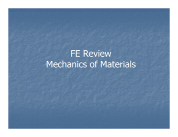
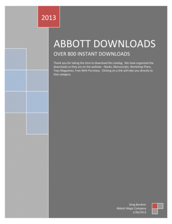
15II.7 UNIAXIAL TENSILE RESPONSE OF SELECTEDMETALS & POLYMERSFigure 2.1 Tensile response of some common metalsFigure 2.2 Tensile response of some common polymers
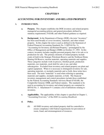
16III. MATERIAL PROPERTY CHARTSIII.1 YOUNG’S MODULUS – DENSITYFigure 3.1:Young’s modulus, E , against density, ρ .The design guide-lines assist inselection of materials for minimum weight, stiffness-limited design. (Data courtesy of GrantaDesign Ltd)
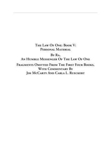
17III.2 STRENGTH – DENSITYFigure 3.2: Failure strength, σ f , against density, ρ . Failure strength is defined as the tensileelastic limit (usually yield stress) for all materials other than ceramics, for which it is thecompressive strength. The design guide-lines assist in selection of materials for minimum weight,strength-limited design. (Data courtesy of Granta Design Ltd)
18III.3 YOUNG’S MODULUS – STRENGTHFigure 3.3: Young’s modulus, E , against failure strength, σ f . Failure strength is defined asthe tensile elastic limit (usually yield stress) for all materials other than ceramics, for which it isthe compressive strength. The design guide-lines assist in the selection of materials for maximumstored energy, volume-limited design. (Data courtesy of Granta Design Ltd)
19III.4 FRACTURE TOUGHNESS – STRENGTHFigure 3.4: Fracture toughness (plane strain), K IC , against failure strength, σ f . Failurestrength is defined as the tensile elastic limit (usually yield stress) for all materials other than2/ πσ 2f , which isceramics, for which it is the compressive strength. The contours show K ICapproximately the diameter of the process zone at a crack tip. Valid application of linear elasticfracture mechanics using K requires that the specimen and crack dimensions are large comparedto this process zone. The design guide-lines are used in selecting materials for damage tolerantdesign. (Data courtesy of Granta Design Ltd)
20III.5 MAXIMUM SERVICE TEMPERATUREFigure 3.5: Maximum service temperature. The shaded bars extend to the maximum servicetemperature – materials may be used safely for all temperatures up to this value, withoutsignificant property degradation. (Note: there is a modest range of maximum servicetemperature in a given material class – not all variants within a class may be used up to thetemperature shown, so caution should be exercised if a material appears close to its limit).NB: For full names and acronyms of polymers – see Section V. (Data courtesy of Granta DesignLtd)
21III.6 MATERIAL PRICE (PER KG)Figure 3.6: Material price (per kg), C m (2003 data). C m represents raw material price/kg,and does not include manufacturing or end-of-life costs.NB: For full names and acronyms of polymers – see Section V. (Data courtesy of Granta DesignLtd)
Polymer Foams Thermosets Thermoplastics (Data courtesy of Granta Design Ltd)Natural Materials can only be machined, thoughsome woods are also hot formed.Polymer Composites are shaped by dedicatedforming techniques, and are difficult to machine.Ceramics are all processed by powder methods, andGlasses are also moulded. Both are difficult tomachine.Notes on other materials: Titanium AlloysMachining Nickel Alloys Aluminium, Copper, Lead,Magnesium, Zinc AlloysInjectionMouldingElastomersPolymers Low Alloy/Stainless Steels Low Carbon SteelsBlowMouldingFigure 4.1b: Polymers and FoamsNon-ferrousExtrusion SheetForming Medium/High Carbon SteelsCompressionMouldingPowderMethods Cast stingMetalsDieCastingFigure 4.1a: MetalsInvestmentCastingIV.1 MATERIAL – PROCESS COMPATIBILITY MATRIX (SHAPING)IV. PROCESS ATTRIBUTE CHARTSRolling/ForgingCompositeFormingMachining22
23IV.2 MASSMetal shapingSand castingInvestment CastingRolling/ForgingExtrusionSheet formingCeramicshapingPolymer andcomposite shapingDie castingPowder methodsMachiningInjection mouldingBlow mouldingCompression mouldingRotational mouldingPolymer castingComposite forming10-310-20.1110102103104Mass (kg)Figure 4.2: Process attribute chart for shaping processes: mass range (kg)IV.3 SECTION THICKNESSPolymer andcomposite shapingCeramicshapingMetal shapingSand castingDie castingInvestment CastingRolling/ForgingExtrusionSheet formingPowder methodsMachiningInjection mouldingBlow mouldingCompression mouldingRotational mouldingPolymer castingComposite forming10-410-310-20.11Section thickness (m)Figure 4.3: Process attribute chart for shaping processes: section thickness (m)(DATA COURTESY OF GRANTA DESIGN LTD)
24IV.4 SURFACE ROUGHNESSMetal shapingSand castingInvestment CastingRolling/ForgingExtrusionSheet formingCeramicshapingPolymer andcomposite shapingDie castingPowder methodsMachiningInjection mouldingBlow mouldingCompression mouldingRotational mouldingPolymer castingComposite forming0.1110102Roughness (µm)Figure 4.4: Process attribute chart for shaping processes: surface roughness (µm)IV.5 DIMENSIONAL TOLERANCEPolymer andcomposite shapingCeramicshapingMetal shapingSand castingDie castingInvestment CastingRolling/ForgingExtrusionSheet formingPowder methodsMachiningInjection mouldingBlow mouldingCompression mouldingRotational mouldingPolymer castingComposite forming10-20.1110Tolerance (mm)Figure 4.5: Process attribute chart for shaping processes: dimensional tolerance (mm)
25IV.6 ECONOMIC BATCH SIZEPolymer andcomposite shapingCeramicshapingMetal shapingSand castingDie castingInvestment CastingRolling/ForgingExtrusionSheet formingPowder methodsMachiningInjection mouldingBlow mouldingCompression mouldingRotational mouldingPolymer castingComposite forming110102103104105106107Economic batch size (units)Figure 4.6: Process attribute chart for shaping processes: economic batch size (Data courtesyof Granta Design Ltd)
FerrousNon-ferrousMetalsCutting tools, springs, bearings, cranks, shafts, railway trackGeneral mechanical engineering (tools, bearings, gears, shafts, bearings)Steel structures (“mild steel”) – bridges, oil rigs, ships; reinforcement for concrete; automotive parts,car body panels; galvanised sheet; packaging (cans, drums)Springs, tools, ball bearings, automotive parts (gears connecting rods etc)Transport, chemical and food processing plant, nuclear plant, domestic ware (cutlery, washingmachines, stoves), surgical implements, pipes, pressure vessels, liquid gas containersHigh Carbon SteelsMedium Carbon SteelsLow Carbon SteelsLow Alloy SteelsStainless SteelsRoof and wall cladding, solder, X-ray shielding, battery electrodesAutomotive castings, wheels, general lightweight castings for transport, nuclear fuel containers;principal alloying addition to Aluminium AlloysGas turbines and jet engines, thermocouples, coinage; alloying addition to austenitic stainless steelsAircraft turbine blades; general structural aerospace applications; biomedical implants.Die castings (automotive, domestic appliances, toys, handles); coating on galvanised steelLead AlloysMagnesium AlloysNickel AlloysTitanium AlloysZinc AlloysAerospace engineering, automotive bodies and panels, lightweight structures and shipsHeat-treatable AlloysElectrical conductors and wire, electronic circuit boards, heat exchangers, boilers, cookware,coinage, sculpturesElectrical conductors, heat exchangers, foil, tubes, saucepans, beverage cans, lightweight ships,architectural panelsNon-heat-treatable AlloysCopper AlloysAutomotive parts (cylinder blocks), domestic appliances (irons)Casting AlloysAluminium AlloysAutomotive parts, engine blocks, machine tool structural parts, lathe bedsCast IronsApplicationsV.1 METALS: FERROUS ALLOYS, NON-FERROUS ALLOYSV. CLASSIFICATION AND APPLICATIONS OF ENGINEERING MATERIALS26
ElastomerPolymer reneNatural RubberPolychloroprene (Neoprene)Polyurethane ElastomersPackaging, buoyancy, cushioning, sponges, sleeping matsThermal insulation, sandwich panels, packaging, buoyancyRigid Polymer FoamFurniture, boats, sports goodsFlexible Polymer FoamElectrical plugs, sockets, cookware, handles, adhesivesNon-stick coatings, bearings, skis, electrical insulation, tapePolyesterPTFEPolytetrafluoroethylene (Teflon)Pipes, gutters, window frames, packagingPhenolicsPVCPolyvinylchlorideCushioning, seating, shoe soles, hoses, car bumpers, insulationAdhesives, fibre composites, electronic encapsulationtp-PUPolyurethane ThermoplasticsToys, packaging, cutlery, audio cassette/CD casesRopes, garden furniture, pipes, kettles, electrical insulation, astroturfZips, domestic and appliance parts, handlesAircraft windows, lenses, reflectors, lights, compact discsBlow moulded bottles, film, audio/video tape, sailsPackaging, bags, squeeze tubes, toys, artificial jointsElectrical connectors, racing car parts, fibre compositesSafety goggles, shields, helmets; light fittings, medical componentsGears, bearings; plumbing, packaging, bottles, fabrics, textiles, ropesPackaging, golf balls, blister packs, bottlesTool and cutlery handles, decorative trim, pensCommunication appliances, automo
In plane strain, the relationship between stress intensity factor K and strain energy release rate G is: E G EG K 1 ν2 (as 1ν2 0.) Plane strain fracture toughness and toughness are thus related by: IC 2 IC IC 1 EG EG K ν “Process zone size”