Transcription
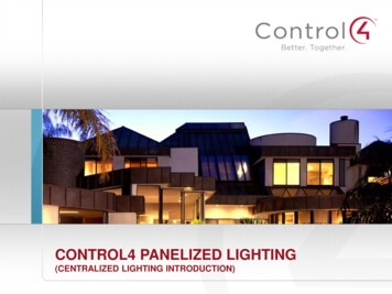
CONTROL4 PANELIZED LIGHTING(CENTRALIZED LIGHTING INTRODUCTION)
Recommended Courses It is recommended that you watch Control4 LightingFundamentals before watching this module– Electricity Basics and Dimming Technologies– Load Types You will be tested on some of these concepts in a PanelizedLighting exam after all modules are completed1/27/2015 2013 Control4 Corporation
Introduction Agenda Intro to Panelized Lighting System Overview System Components How Everything Goes Together1/27/2015 2013 Control4 Corporation
Intro to Control4Panelized Lighting
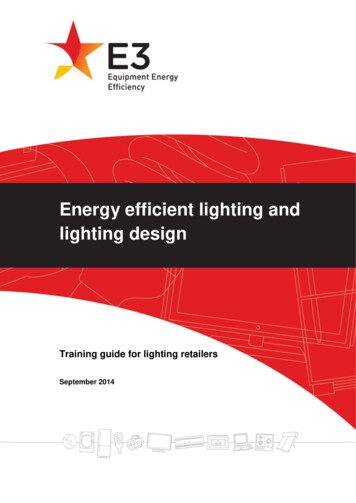
Traditional Lighting WiringBreaker PanelDimmers/Switches in Each Room to Control Lights1/27/2015 2013 Control4 Corporation
Traditional Room Light Switches1/27/2015 2013 Control4 Corporation
Designers Want a Cleaner Look Interior Designers andsome customers maynot want multipledimmers or switchesthroughout the house1/27/2015 2013 Control4 Corporation
Is There a Better Way?1/27/2015 2013 Control4 Corporation
Control4Panelized Lighting
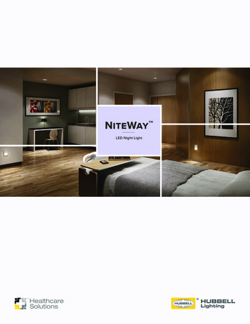
Control4 Panelized Lighting WiringControl4 Central PanelBreaker Panel Each Circuit (5 to 20 Amp) is wiredfrom Breaker to Control4 CentralPanel(s). The lighting loads are cabled toControl4 panels that reside incentral or multiple locations.Zigbee Keypads, Wired Keypads,Remotes and Control4 Navigatorscontrol all the lights. No Switches or Dimmersthroughout the house1/27/2015 2013 Control4 Corporation
Advantages of Panelized Lighting Advantages– Eliminate Wall Acne– Increase Reliability/Robustness1/27/2015 2013 Control4 CorporationControlled with Keypads
Cleaner Look-Robust Performance1/27/2015 2013 Control4 Corporation
Limitation of Panelized Lighting Limitation– Usually only possible in new construction or major remodel1/27/2015 2013 Control4 Corporation
Basic SystemOverview
Control4 Panelized Lighting Overview Residential & Commercial 110V to 277V Worldwide voltages Residential & Commercial Ethernet-Based Use Keypads to Control Lights Use On-Screen TV, Touch Screens, andMobile Devices to Control Lights DIN Rail Form Factor mounting1/27/2015 2013 Control4 Corporation
What is “DIN Rail”? DIN is an internationalstandards body– Deutsches Institut fürNormung DIN standards 43-880and 46277-3 define a setof specifications for railsand devices to mount onthose rails “DIN Rail” is really just amounting mechanism1/27/2015 2013 Control4 Corporation
Why Did We Choose DIN Rail? Wanted to create a global product DIN rail products and panels are very commonoutside of North America– Customers are very familiar with how to install them– Off-the-shelf panels are readily available With just a few adaptations, we were able tomake the system equally applicable to NorthAmerican markets– High-voltage/low-voltage separation on modules– Higher maximum wattage ratings– Panels designed specifically for North America1/27/2015 2013 Control4 Corporation
System Design System Design is done in Composer– All the same capabilities as existing lightingplus some new features New light proxy Load groups – treat multiple loads as asingle load Advanced Scene Control– Toggle scenes, track scene state,ramp & fade scenes, add delaysto scenes, flash lightsNote: Be sure to watch the Advanced Lighting Scene training module on Control4 University1/27/2015 2013 Control4 Corporation
What If The Network or Controller Is Down? Three different ways that lights can still becontrolled:– Failover behavior for wired keypads– Remote overrides from hidden switch– Local overrides on the modules1/27/2015 2013 Control4 Corporation
SystemComponents
Cabinet FamilyModulesTerminalsPanels1/27/2015 2013 Control4 Corporation
Wired Keypad FamilyDecora Wired Keypads4-Channel dry contactinput module1/27/2015Square Wired KeypadsBus Power Supply 48VDC 2013 Control4 CorporationEthernet Bus Gateway
Module Family8 Channel Dimmer8 Channel Relay8 Channel 0-10V Dimmer8 Port Ethernet Switch1/27/2015 2013 Control4 Corporation
Modules – Physical Specs Meets DIN standard Work with off the shelf DIN rail cabinets Dimensions:– Full Size Modules 215mm wide 12M– Half Size Modules 107mm wide 6M Line-voltage connectors accept up to 12 gauge or 4mm2wire (solid or stranded)– External relay and low voltage connections accept up to 16gauge or 1.5mm2 Standard RJ-45 for Ethernet connection1/27/2015 2013 Control4 Corporation
8 Channel Dimmer
8-Channel Dimmer Features 110V to 277V, 50/60Hz 2 Line In (Max) from CircuitBreaker box– 120V – 2 Lines In must be on samephase Can control 8 different loads– Auto adaptive – detects load typeand automatically selects forwardor reverse phase dimming– Can control dimmable and nondimmable loads Each load wattage rating dependson voltage (110, 240, 277) Communicates to primary controllervia network switch Triggered by keypads and Control4navigators1/27/2015 2013 Control4 Corporation(C4-DIN-8DIM-E)
8 Channel DimmerLine 1 from Circuit Breaker1/27/2015 2013 Control4 Corporation
8 Channel DimmerIf needed, Line 2 from Circuit Breaker1/27/2015 2013 Control4 Corporation
8 Channel DimmerA jumper to Line 2 from Line 1 must beused when using a single line feed.1/27/2015 2013 Control4 Corporation
Phase ExplanationLet’s talk about Power Lines and Phases1/27/2015 2013 Control4 Corporation
Connecting Service Lines to Breakers2 Service Lines from Power CompanyEach line 120V (Total 240V)120V SinglePole CircuitBreaker(ex. Outlets,lights, etc.)1/27/2015240V DoublePole CircuitBreaker(ex. Dryer,Range, etc.) 2013 Control4 Corporation
2 Service Lines – 2 Phases1/27/2015 2013 Control4 Corporation
Each Line on Different PhaseService Line L1(Black)connected tocircuit breakersall on the samephase1/27/2015 2013 Control4 Corporation
Each Line on Different PhaseService Line L2(Red)connected tocircuit breakersall on the samephase1/27/2015 2013 Control4 Corporation
Lines on Same Phase The 8 channel Dimmer Line 1 and 2 as well as the 8channel Relay Lines 1-4 need to be on the same phase. If connected to 2 different phases, light flickering couldoccur. Work with the electrician to wire the lines to theappropriate circuit breakers that are on the same phase.1/27/2015 2013 Control4 Corporation
8 Channel DimmerLight Loads 1-8 as needed1/27/2015 2013 Control4 Corporation
8-Channel Dimmer Ratings 110V to 277V, 50/60HzTwo 20 amp (max) line-ins* Do not exceed module max– Each line-in serves 4-channels– If only one line-in is needed, a jumper can be used to serve all 8-channels Line-in 1 powers the module so it must be used120V inControl4Cabinet240V inControl4Cabinet277V inControl4Cabinet120V instandardunventedDIN railcabinet240V instandardunventedDIN railcabinet3200W6000W6000W1920W3840WLine-In 1 Max*1920W3840W3840W1000W2000WLine-In 2 Max*1920W3840W3840W1000W2000WModule max with one line-in1920W3840W4400W1920W3840WSingle channel WModule max with two line-insSingle channel non-dimmable maxNote: Arc-Fault breakers limit maximum dimming wattage per line-in to 1000W @ 120V and 2000W @ 240V1/27/2015 2013 Control4 Corporation
8-Channel Dimmer – Load Types Auto-Adaptive Dimmer– Forward phase (leading edge) andreverse phase (trailing edge)– Dims many different load types: Incandescent Halogen Magnetic (iron-core) transformers(MLV); Electronic (solid state) transformers(ELV); Phase-cut dimmable fluorescents &CFLs; Phase-cut dimmable formerDimmableLED Bulbs– Automatically detects each load typeand sets appropriate dimming profile Can be forced to forward-phase or reversephase if needed. (Must do this with powerboosters.)DimmableCompactFluorescent1/27/2015 2013 Control4 CorporationHalogen
8-Channel Dimmer – Load Types Can be set to control nondimmable loads as well– Forces preset level to 100%,ramp rates to zero, andminimum on to 100%Fluorescent– Lower load rating thandimmable loads – 500W or1/8 HP per channelExhaust Fans1/27/2015 2013 Control4 Corporation
8-Channel Dimmer – ConnectionsLoad 1 – Living Room CansLoad 2 – Kitchen CansLoad 3 – Living Room OverheadsLoad 4 – Kitchen Bar Overheads1/27/2015 2013 Control4 Corporation
8-Channel Dimmer – Buttons & LEDs 8 Channel Buttons– Press and release to go to preset level– Press and hold to cycle dim– If in a fault state, Press and hold to reset any channelfaults 8 Channel LEDs– Indicate on/off of state of each channel as well as anychannel faults 1 Module Override Button– Press and release to set module scene– Press and hold to save current load levels as themodule scene 1 Module Override LED– Indicates power to module and any fault states 1 Ethernet Link/Activity LED 1 Reset Button (recessed)1/27/2015 2013 Control4 Corporation
8 Channel Dimmer8 Channel push buttons and LED indicators1/27/2015 2013 Control4 Corporation
Module LED Indicator Lights1/27/2015 2013 Control4 Corporation
Local Overrides at Module Channel buttons on the front ofeach module allow each channelto be controlled directly Module button toggles overridescene– Same scene that a switch wired tothe auxiliary terminal controls Buttons are easily accessiblewithout removing panel coverNote: In the factory setting, all channels are set to Switch Mode –dimming properties are set by using module setup or Composer1/27/2015 2013 Control4 Corporation
8 Channel DimmerModule Override Button1/27/2015 2013 Control4 Corporation
Operation of the Buttons Channels 1-8– Click will toggle load on and off– Hold will ramp and fade ifdimmable Module Override– Click will toggle betweenoverride scene and all channelsoff– Hold for 5 seconds will set theoverride scene to the currentchannel levels1/27/2015 2013 Control4 Corporation
Hidden Override Switches Auxiliary terminal on module canbe wired to a standard toggleswitch in closet or other out ofthe way place. Toggles an override “scene”which is stored on the module –no Controller required. Override scene can be setup inComposer or even from theModule.1/27/2015 2013 Control4 Corporation
8 Channel DimmerAuxiliary switch for manual override1/27/2015 2013 Control4 Corporation
8 Channel DimmerReset Button – No reason to remove power to reboot1/27/2015 2013 Control4 Corporation
8 Channel DimmerBackTopRJ-45 Ethernet Connection for Network1/27/2015 2013 Control4 Corporation
8 Channel DimmerNetwork Link / Activity LED Indicator1/27/2015 2013 Control4 Corporation
8 Channel Relay
8-Channel Relay Features 110V to 277V, 50/60Hz 4 Line In (Max) from CircuitBreaker box– Each line serves 2 loads– 120V – 4 Lines In must be onsame phase On/Off Control(C4-DIN-8REL-E) Communicates to primarycontroller via network switch Triggered by keypads andControl4 navigators1/27/2015 2013 Control4 Corporation
8 Channel RelayLine 1-4 from Circuit Breaker1/27/2015 2013 Control4 Corporation
8 Channel RelayLoads 1-8 if needed1/27/2015 2013 Control4 Corporation
8 Channel RelayAuxiliary switch for manual override1/27/2015 2013 Control4 Corporation
8-Channel Relay Ratings 110V to 277V, 50/60Hz Four 20 amp (max) line-ins– Each line-in serves 2-channels High in-rush relays can handle large banks of fluorescents, motors,pumps, etc.1/27/2015120V240V277VModule max64A64A64AEach line-in max16A16A16ASingle channel max16A1HP16A2HP16A 2013 Control4 Corporation
8-Channel Relay – Load Types On/Off Only Can pretty much control any loadtype, but the ones that willtypically be used able Fluorescents & CFLsNon-Dimmable LEDsLandscape lighting transformersOutlets 2013 Control4 Corporation
8 Channel0-10V Dimmer
0-10V Dimming Basics Has been a common dimmingmethod for fluorescentballasts for years Rapid increase in LEDs thatuse 0-10V dimming 0-10V is just an analog controlsignalBallast– The ballast or LED driverinterprets the 0-10V controlsignal and performs the dimming0-10V LEDIncreasing1/27/2015 2013 Control4 Corporation
0-10V Dimming Basics While a standard exists, it’s often ignored– Control voltage varies 1-10V (standard)0-10V10-0V10-1V– Sink/source current not always followed Standard says that the ballast/driver should be thecurrent source and the control device should be thecurrent sink. Specs for the ballast/driver should be checkedbefore installation – check with electrician. Affects the number of ballasts/drivers that can becontrolled as one group.LED Driver Separate on/off control frequently required– Almost all fluorescent ballasts, some LEDs– 0V corresponds to minimum dimmed level –not off– Switch line voltage to turn on/off1/27/2015 2013 Control4 CorporationFluorescentBallast
8-Channel 0-10V Dimmer Features Input: 110V to 277V, 50/60Hz Controls up to eight 0-10V or 110V fluorescent ballasts andLEDs––100mA per channel current sink ( 50ballasts)25mA per channel current source ( 12ballasts) Dry contacts for triggeringexternal relays for on/off control(e.g. Leviton Power Pack Relay –commonly used with Motion Sensors)– Can also use Control4 RelayModule for on/off control. Same override capabilities asdimmer and relay.1/27/2015 2013 Control4 Corporation(C4-DIN-8TV-E)
8 Channel 0-10V DimmerLine In from Circuit Breaker1/27/2015 2013 Control4 Corporation
8 Channel 0-10V DimmerLight Loads 1-8 as needed1/27/2015 2013 Control4 Corporation
8 Channel 0-10V DimmerExternal Relays 1-8 as needed1/27/2015 2013 Control4 Corporation
Example of 0-10V WiringLED Driver - dimmingHigh Voltage0-10V Dimmer – control signal1/27/2015 2013 Control4 CorporationHigh Voltage
8 Channel 0-10V Dimmer On/Off Control– Some loads don’t require separate on/off control– LED Driver or ballast handles automatically1/27/2015 2013 Control4 Corporation
8 Channel 0-10V Dimmer Two options when separate on/off control is required– Use Control4 Relay Module– Use external relay (e.g. Leviton Power Pack) connected to externalrelay terminal on 0-10V module.1/27/2015 2013 Control4 Corporation
External Relay vs. Control4 Relay External RelayAdvantages– Lower cost– Works without Controller External RelayDisadvantages– Electrician must find aplace to install and wire theexternal relay1/27/2015 2013 Control4 Corporation
External Relay vs. Control4 Relay Control4 RelayAdvantages– Simplified Wiring – wire incabinet with everythingelse– Provides energymeasurement of the load Control4 RelayDisadvantages– Higher cost1/27/2015 2013 Control4 Corporation
8-Channel 0-10V Dimmer – Load Types 0-10V and 1-10V fluorescentballasts and LED drivers Sink or Source– The 0-10V standard defines theballast/driver as the source andthe control device as the sinkbut not every ballast/driverconforms to that standard.1/27/2015 2013 Control4 Corporation
8 PortEthernet Switch
8-Port Ethernet Switch Features Simplifies wiring – Pull a single Cat-5 intocabinet and then just use patch cableswithin the cabinet.––More convenient to use, but not requiredCan pull Cat5e from network Central Switch Standard 10/100 Ethernet Switch Same form factor as dimmer and relay(C4-DIN-8ESW-E) Single connector for line, neutral & ground– Powered by 110-277V 8 RJ-45 connectors for Ethernet 8 Link/Activity LEDs and 1 Power LED 1 reset button (recessed) on front1/27/2015 2013 Control4 Corporation
8 Port Ethernet SwitchLine in from Circuit Breaker1/27/2015 2013 Control4 Corporation
8 Port Ethernet SwitchConnection to Network Devices1/27/2015 2013 Control4 Corporation
Panel FamilyPanelsTerminal Blocks1/27/2015 2013 Control4 Corporation
Terminal Blocks Used for terminating wiring in the panel from thecircuit breaker to the modules Different terminal block for each module type– Each module type requires different wiringconfigurations.– Comes as a complete assembly alreadymounted on the rail. Sold separately– Purchased at rough-in(C4-DIN-TB-8DIM)Used with Control4 8-Channel Dimmer(C4-DIN-TB-8REL)Used with Control4 8-Channel Relay Similar blocks used in Crestron & Lutron panels soelectricians are familiar with them. Built-in jumpers between line-ins and loads allowloads to be turned on/off using the breaker prior toinstalling modules.1/27/2015 2013 Control4 Corporation(C4-DIN-TB-PO)Used with 0-10V Dimmer,Ethernet Switch and Bus Power Supply
Why Wire to a Terminal Block? It gives the electrician a place toterminate the wires during the rough-in It jumpers the neutrals together.Without the terminal blocks, this has tobe done with wire nuts, which can bevery messy. The jumpers between the hot and loadallow the electrician to test their wiringand ensure that there are no shortcircuits prior to connecting anexpensive module.– Damage due to shorts are not coveredunder warranty. It allows the lights to be turned onduring construction simply by flippingon the breaker.1/27/2015 2013 Control4 Corporation
Panels (2 Slot & 5 Slot) Flush mounts in a standard 16” on center stud bay– Can also be surface mounted Two versions– Large – 5 slots (65” high)– Small – 2 slots (35” high) Allow all field wiring to be terminated at rough-in toterminal blocks Modules can be mounted and wired to terminal blocksduring trim-out phase1/27/2015 2013 Control4 Corporation
Panels – Features Modules protrude through front cover toallow easy access to buttons & LEDs Remove front cover for access to wiring Plenty of room at top and bottom for wires Pivoting high-voltage / low-voltage (Class 1/ Class 2) divider plate provides maximumuse of knockouts Tie-backs on sides for cable management1/27/2015 2013 Control4 Corporation
Wired Keypad Family1/27/2015Decora Wired KeypadsSquare Wired KeypadsBus Power Supply 48VDCEthernet Bus Gateway 2013 Control4 Corporation
Wired Keypads Available in Decora size andsquare form factors. Utilize an RS-485 based bus forcommunication– Requires Bus Ethernet Gateway Low Voltage – Powered via oneor more Bus Power Supplies1/27/2015 2013 Control4 Corporation
Wired Keypad - Features New, elegant design with first rate fit & finishConfigurable from 2 to 7 buttons– Can mix and match different button sizes for up to37 different possible button layouts– Ships with all buttons necessaryfor any configuration Backlit engraving– RBG backlight can be controlled separately fromthe status LEDs Optional split up/down buttons.– Can be dedicated to a single function or be tied tothe last button pressed on the keypad. Ambient light sensor automatically adjustsbacklight and status LED brightness dependingon room light level.Available in 9 colors1/27/2015 2013 Control4 Corporation
Wired Keypad Failover Behavior Works even if both the Controller andthe network router are offline – as longas the network switch is functional. Can define in Composer a failoverbehavior for any button on a wiredkeypad.– Control a single light or multiple lights Control module listens and activatesthe lights for all keypad button pressesif the Controller doesn’t respond in atimely fashion.1/27/2015 2013 Control4 Corporation
Wired Keypad Failover Behavior While multiple lights can be controlledfrom a single button, actual lightingscenes can no be activated as theyrequire Director. In Failover Mode, any one button canonly turn on or off lights. They can’ttoggle lights. Each light can only be controlled byone keypad in failover mode. Threeway’s won’t work.1/27/2015 2013 Control4 Corporation
Configuration Samples1/27/2015 2013 Control4 Corporation
Engraving All buttons are available to be customengraved to what the customer wants. Same process for engraving as the NextGeneration devices.1/27/2015 2013 Control4 Corporation
Engraving All buttons are available to be customengraved to what the customer wants. Same process for engraving as the NextGeneration devices.1/27/2015 2013 Control4 Corporation
Bus Power Supply Provides 48V Power to WiredKeypads and Bus EthernetGateway. Add two power supplies to asingle bus to provide additionalpower if needed. The initial Power Supply mountsin the Control4 panel separatelyfrom the rail and does not occupya slot space.1/27/2015 2013 Control4 CorporationPowerSupplyKeypadGatewayKeypad
Bus Ethernet Gateway Provides communication Gatewaybetween the RS-485 Bus keypadsand the Ethernet Controller andModules.NetworkGateway Same form factor as Control4Panelized Lighting Modules excepthalf the width.– Mounts in Control4 Panel using ½ slot– Mounts in any standard DIN rail panelKeypad 6M Low-voltage – powered by the BusPower Supply, not line voltage.1/27/2015 2013 Control4 CorporationKeypadKeypad
Bus Cable Recommendation Recommended cable types:– Common control system cables such as Belden 1502R or1502P. 18 gauge pair for power 22 or 24 gauge twisted pair for data– Cat5e or Cat6 is not recommended. Installation experience canbe poor and can be hard to diagnose when problems arise. It’s also a good practice to use a loopback cable as aprecaution in case the cable in the wall gets damaged– Note: The loopback cable does not get connected to anythingunless it is needed.1/27/2015 2013 Control4 Corporation
Bus Wiring Topology No:1Power Supply & Gateway at the BEGINNING of the busPowerSupplyGatewayKeypadKeypadKeypadMax 40 keypads – Max 1000ft (300m)1/27/2015 2013 Control4 Corporation
Bus Wiring Topology No:2Power Supply & Gateway at the MIDDLE of the busKeypadKeypadPowerSupplyGatewayMax 25 keypads –Max 1000ft (300m)KeypadMax 25 keypads –Max 1000ft (300m)Max 50 keypads – Max 2000ft (600m)1/27/2015Keypad 2013 Control4 Corporation
Bus Wiring Topology No:3Two Power Supplies & Gateway at the MIDDLE of the busKeypadKeypadPower SupplyGatewayMax 40 keypads –Max 1000ft (300m)Power SupplyKeypadMax 40 keypads –Max 1000ft (300m)Max 80 keypads – Max 2000ft (600m)1/27/2015Keypad 2013 Control4 Corporation
Multiple GatewaysKeypadKeypadKeypadKeypad1/27/2015Power SupplyGatewayPower SupplyPower SupplyGatewayPower Supply 2013 Control4 CorporationKeypadKeypadKeypadKeypad
Bus Wiring Loopback ExampleLoopback cable run along with daisy chain, but not terminatedPowerSupplyGatewayKeypad1/27/2015Keypad 2013 Control4 CorporationKeypadKeypad
Bus Wiring Loopback ExampleKeypads 2, 3, & 4 don’t work because of damaged wiringPowerSupplyGatewayKeypad1/27/2015Keypad 2013 Control4 CorporationKeypadKeypad
Bus Wiring Loopback ExampleTerminate Loopback to Gateway and Last KeypadDisconnect cable between Keypad #1 and #2Loopback serves as second Daisy Chain as a precautionPowerSupplyGatewayKeypad1/27/2015Keypad 2013 Control4 CorporationKeypadKeypad
Bus Wiring Detail No:1Power Supply & Gateway at the BEGINNING of the bus Wiring in this topology will result in a maximum number of 40Keypads and a maximum cable length of 1000ft1/27/2015 2013 Control4 Corporation
Bus Wiring Detail No:2Power Supply & Gateway at the MIDDLE of the bus 25 keypads per individual chain and a max of 2 chains (do notexceed max 25 keypads per chain) Wiring in this topology will result in a maximum number of 50Keypads and a maximum cable length of 2000ft.1/27/2015 2013 Control4 Corporation
Bus Wiring Detail No:3Two Power Supplies & Gateway at the MIDDLE of the bus 40 keypads per individual chain and a max of 2 chains (do notexceed max 40 keypads per chain) Wiring in this topology will result in a maximum number of 80Keypads and a maximum cable length of 2000ft.1/27/2015 2013 Control4 Corporation
Star Topology 4th wiring option available utilizing StarTopology. We support 8 spokes coming off a dualpower supply/gateway location. Each power supply can support up to 4spokes. Each spoke can support up to 10 keypadsfor a total of up to 80 keypads. A single spoke can be 1000 feet long. The total amount of cable of the 8 spokescannot exceed 4000 feet.1/27/2015 2013 Control4 Corporation
Bus Wiring Detail No 41/27/2015 2013 Control4 Corporation
Bus Wiring Detail No 41/27/2015 2013 Control4 Corporation
Bus Wiring Detail No 5Note that both power supplies areconnected to the same ground wireWire the bus using a star topology with the gateway and two (2) power supplies at the center of each spoke.Wiring with this topology will result in a maximum cable length of 4,000 feet (1,219m) and up to of 80keypads.1/27/2015 2013 Control4 Corporation
System Diagram with Wired KeypadsC4 Panelized LightingLine PowerPowerSupplyControl4 EthernetSwitch (would belocated in Panel)KeypadKeypadKeypadRS- 485GatewayBus Ethernet GatewayEthernetController1/27/2015 2013 Control4 CorporationRS-485Keypad
System Diagram with ZigBee KeypadsC4 Panelized LightingLine PowerPowerSupplyControl4 EthernetSwitch (would belocated in 85EthernetControllerZigBee1/27/2015 2013 Control4 CorporationWiredKeypad
Wired vs. Wireless Keypads Wired Keypads– Work in failover mode– Have the reliability of a wire Wireless Keypads– Add to the ZigBee Mesh The best option is probably a mix of wiredand wireless Example:– Use a Wired Keypad at the main entranceto a room to take advantage of the failover– Use Wireless Keypads for at least some ofthe additional keypad locations to build outthe ZigBee mesh.1/27/2015 2013 Control4 Corporation
Best Practices for Keypad Placement1/27/2015 2013 Control4 Corporation
Keypad Placement With PanelizedLighting, keypadplacement is critical.– Keypads are the onlytactile connection to aPanelized System.– You will probably installmore than you originallythought.1/27/2015 2013 Control4 Corporation
Locations for Keypad PlacementTop and bottom of stairsEntrance to a room1/27/2015 2013 Control4 Corporation
Locations for Keypad PlacementShowers, tubs & toiletsBedside1/27/2015 2013 Control4 Corporation
Locations for Keypad PlacementInside exterior doorsKitchen Sinks1/27/2015 2013 Control4 Corporation
Locations for Keypad PlacementLarge roomsClosets1/27/2015 2013 Control4 Corporation
Keypad Placement for Large Rooms Plan on keypadsaccessible frommultiple locations,even if therearen’t multipleentrances1/27/2015 2013 Control4 Corporation
Follow National or Local Codes Follow the national orlocal code for height forkeypads.– This can also varydepending on the country1/27/2015 2013 Control4 Corporation48” (1.22 meters) If a code does notspecify, typicalmounting height is 48inches (1.22 meters) tothe center of thekeypad.
Account for Molding Remember toaccount for moldingwhen placingkeypads near doorsor windows. Verify the width ofthe molding prior toinstalling the roughin box.1/27/2015 2013 Control4 Corporation
Verify Wall Thickness Verify the final wall thicknessprior to installing rough-inboxes.– Thickness of the wall finish couldbe tile, thicker drywall, etc. If the wall thickness isunknown, use an adjustabledepth box.1/27/2015 2013 Control4 Corporation
Don’t Forget! Keypad buttons can beused for controllingthings other than lights.–––––1/27/2015MusicLocksGarage DoorsGatesSecurity 2013 Control4 Corporation
Number of Buttons and Keypads Multiple keypads withlarger buttons may bepreferable to a singlekeypad with smallerbuttons. Ask the customer whattheir preferences are!1/27/2015 2013 Control4 Corporation
Putting It All Together
How the Pieces Go TogetherTerminalBlocksNetworkNetwork andDimmer ModulesCircuit BreakerLight LoadsPanel1/27/2015 2013 Control4 Corporation
Lights On Command – Hard WiredNetworkTerminalBlocksNetwork andDimmer ModulesCircuit BreakerLight LoadsPanel1/27/2015 2013 Control4 CorporationWiredKeypadsHC-800 Primary Controller
Lights On Command – ZigBeeTerminalBlocksNetworkNetwork andDimmer ModulesCircuit BreakerLight LoadsPanel1/27/2015 2013 Control4 CorporationHC-800 Primary Controller
Increase Your Knowledge Be sure to watch these modules on Control4University and read the documentation– Control4 Lighting Fundamentals Electricity Basics and Dimming Technologies Load Types–––––––1/27/2015Designing Panelized Lighting with ComposerInstallation of Panelized LightingInstall, wiring & operation guidesReference guide for electriciansAdvanced Lighting Scenes AgentPlanning GuideInstallation videos 2013 Control4 Corporation
Thank You
Control4 Panelized Lighting Wiring 1/27/2015 2013 Control4 Corporation Each Circuit (5 to 20 Amp) is wired from Breaker to Control4 Central Panel(s). The lighting loads are cabled to Control4 panels that reside in central or multiple locations. Control4 Central Panel Breaker Panel Zigbee Keypads, Wired Keypads, Remotes and .