Transcription
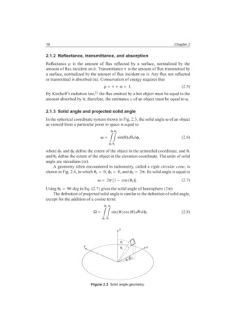
SRBK005-02SRBK005March 13, 201319:10Char Count 016Chapter 22.1.2 Reflectance, transmittance, and absorptionReflectance is the amount of flux reflected by a surface, normalized by theamount of flux incident on it. Transmittance is the amount of flux transmitted bya surface, normalized by the amount of flux incident on it. Any flux not reflectedor transmitted is absorbed ( ). Conservation of energy requires that 1.(2.5)By Kirchoff’s radiation law,22 the flux emitted by a hot object must be equal to theamount absorbed by it; therefore, the emittance ε of an object must be equal to .2.1.3 Solid angle and projected solid angleIn the spherical coordinate system shown in Fig. 2.3, the solid angleas viewed from a particular point in space is equal toof an object2 2sin( ) dθ d , (2.6)1 1where 1 and 2 define the extent of the object in the azimuthal coordinate, and 1and 2 define the extent of the object in the elevation coordinate. The units of solidangle are steradians (sr).A geometry often encountered in radiometry, called a right circular cone, isshown in Fig. 2.4, in which 1 0, 1 0, and 2 2 . Its solid angle is equal to 2 [1 cos ( 2 )] .(2.7)Using 2 90 deg in Eq. (2.7) gives the solid angle of hemisphere (2 ).The definition of projected solid angle is similar to the definition of solid angle,except for the addition of a cosine term:22sin ( ) cos ( ) dθ d , 11Figure 2.3 Solid angle geometry.(2.8)
SRBK005-02SRBK005March 13, 201319:10Char Count 0Basic Radiometry for Stray Light Analysis17Figure 2.4 Solid angle of a right circular cone.This geometry is illustrated in Fig. 2.5. The units of projected solid angle aresteradians, just as for solid angle.There are a number of common cases for which the value of the projected solidangle is simple to compute. The first of these is the right circular cone (shown inFig. 2.4), which is equal to sin2 ( 2 ) .(2.9)Using 2 90 deg in Eq. (2.9) gives the solid angle of a hemisphere ( ). Theprojected solid angle divided by is often called the geometric configurationfactor (GCF).The projected solid angle of an optical system can be computed from itsworking f -number ( f /# ), which is equal to f(1 m),(2.10)f # DEPwhere f is the effective focal length of the system, DEP is equal to the diameter ofthe entrance pupil (computed as twice the height of the marginal ray), and m is themagnification of the system (which is equal to the image distance divided by theobject distance). The projected solid angle of an optical system is given by7 f/# (2.11) 2 .4 f/# Figure 2.5 Projected solid angle geometry.
SRBK005-02SRBK005March 13, 201319:10Char Count 018Chapter 2nθdAd2ΦdωdAcos(θ)Figure 2.6 Quantities used in the definition of radiance.2.1.4 RadianceThe radiance of a source L is equal toL d 2 ,dA cos ( ) d (2.12)where d is the differential power emitted by the differential projected area of thesource dA cos ( ) into the differential solid angle d , as shown in Fig. 2.6.The units are ph/s-unit area/sr, or in photometric units as candela/m2 (alsocalled “nits”). Radiance is used to quantify the amount of light or “brightness”of a surface: the more flux a surface emits per unit area or the more flux it emitsper projected solid angle, the greater its radiance. It is an elemental radiometricquantity, and other quantities, such as intensity or exitance (discussed later), arederived by integrating it over solid angle or area, respectively. If absorption lossesare neglected, radiance is conserved through an optical system, and thus the radianceof an image is the same as the radiance of the exit pupil and of the scene (it is said tobe “invariant”). A surface whose radiance is constant with respect to the emittanceangle is said to be Lambertian. Though treating a surface as Lambertian is oftena useful approximation, in practice no surface is perfectly Lambertian.2.1.5 Blackbody radianceThe Planck blackbody equation can be used to compute the spectral radiance L (in ph/s-cm2 -sr- m) of an extended source from its temperature:L ( ,T ) 4 C1 ,exp C2 T 1 (2.13)where C1 5.99584 1022 photons- m5 /s-cm2 -sr, C2 14387.9 m-K, and Tis the temperature of the source in kelvin. This function is plotted in Fig. 2.7 as afunction of wavelength for several temperatures.Equation (2.13) does not account for variations in radiance versus wavelengthdue to changes in emissivity of the extended source. These variations, which aredetermined by the chemical composition of the source and which all sources have,can result in an error in the radiance predicted by the Planck equation, and thereforemay need to be considered in the calculation. For example, the spectral radianceof the sun is shown in Fig. 2.8 along with the radiance predicted by the Planckequation for an ideal blackbody at 5800 K. Chemical species in the sun result inabsorption bands that are not predicted by the Planck equation.
SRBK005March 13, 201319:10Char Count 019Basic Radiometry for Stray Light Analysis9E 218E 21Radiance (ph/s-cm2-μm)7E 216E 215E 214E 213E 212E 211E 210014000 K23Wavelength (μm)5000 K46000 KFigure 2.7 Blackbody radiance versus wavelength.9.E 218.E 217.E 21Radiance (ph/s-cm2-str- μm)SRBK005-026.E 215.E 214.E 213.E 212.E 211.E 210.E 000.00.51.01.52.0Wavelength ( μm)5800-K Blackbody2.53.0Measured SolarFigure 2.8 The spectral radiance of an ideal 5800-K blackbody and the measured exoatmospheric spectral radiance of the sun.8
SRBK005March 13, 201319:10Char Count 020Chapter 2Table 2.2 Equivalent solar blackbody temperatures for typical sensor wavebands.WavebandMin ( m) Max ( m)Equivalent Solar BB Error in Band-IntegratedTemperature (K)RadianceName0.40.7VIS58480.436%0.71MIR5761 0.109%13SWIR5986 2.333%35MWIR56561.448%812LWIR49830.758%One of the ways to reduce the magnitude of the error resulting from the useof the Planck equation is to determine the blackbody temperature of the sourcethat minimizes the chi-squared difference between the actual spectrum and theblackbody spectrum in the waveband of interest. This was done for the spectrumshown in Fig. 2.8 (i.e., 5800 K is best-fit), and in Table 2.2 for the visible andIR sensor wavebands. The resulting error in the band-integrated radiance is alsogiven in Table 2.2. Error analysis must be performed to determine the error in anyquantity dependent on this radiance.Figure 2.9 shows the apparent exo-atmospheric radiance of the sun, and assuch it does not account for the reduction in apparent radiance due to 0.40.30.20.1002468101214Wavelength (μm)161820Figure 2.9 Transmittance from ground to space versus wavelength of the atmosphere,looking straight up from the ground.
SRBK005-02SRBK005March 13, 201319:10Char Count 021Basic Radiometry for Stray Light AnalysisTable 2.3 Band-averaged transmittance from ground to space of the atmosphere, lookingstraight up from the ground.WavebandMin ( m)Max ( 2213SWIR0.58135MWIR0.490812LWIR0.726absorption and scattering (extinction), which can significantly reduce it. Atmospheric extinction is a complicated phenomenon that is a function of many variables,including wavelength, the geometry of the path of light through the atmosphere,and weather conditions, to name a few. The software MODTRAN9 was createdto deal with this complexity—it can predict atmospheric extinction as a functionof these variables and more. Figure 2.9 shows the transmittance from ground tospace of the default MODTRAN atmospheric model, looking straight up from theground, which is the maximum transmittance possible from the ground to space.Table 2.3 gives the same transmittance averaged over typical sensor wavebands;this table quantifies the error in apparent radiance of the sun that results fromneglecting atmospheric extinction.The total radiance L in a waveband can be calculated by integrating Eq. (2.13)over the waveband of interest:L 2L d ,(2.14) 1where 1 and 2 are the minimum and maximum wavelengths of the waveband.The wavelength peak corresponding to the peak radiance can be computed fromthe temperature of the blackbody T using Wien’s displacement law for photons: peak 3670,T(2.15)where peak is in m, and T is in kelvin. Integrating Eq. (2.13) over all wavelengthsgives the total radiance emitted by a blackbody L total , which can be expressedusing the Stefan–Boltzman law for photons:Ltotal p T 3,(2.16)where p is the Stefan–Boltzman constant (1.5204 1013 ph/s-cm2 -K3 ). The term in Eq. (2.16) converts the units to radiance (ph/s-cm2 -sr).
Basic Radiometry for Stray Light Analysis 21 Table 2.3 Band-averaged transmittance from ground to space of the atmosphere, looking straight up from the ground. Waveband Average Min ( m) Max ( m) Name Transmittance 0.4 0.7 VIS 0.598 0.7