Transcription
USER GUIDETURBOCORDTM PORTABLE CHARGER120V/240V: DUAL VOLTAGEAeroVironment EV Solutions
2013 AeroVironment, Inc. All rights reserved.AeroVironment, EV Solutions, and the AeroVironment logo are trademarks of AeroVironment, Inc.Corporate names, trademarks, registered trademarks, service marks, symbols, and logos stated herein are property of theirrespective companies.Specifications are subject to change without notice. Images of the Dual voltage charger are representative; production models may vary. Dual voltage charger may be branded under different names.No portion of these materials may be duplicated, used or disclosed without prior written permission from AeroVironment, Inc.Disclaimer: This user guide includes the latest information available at the time of printing. AeroVironment, Inc. reserves theright to make changes to this user guide and/or product without further notice. Changes or modifications to this product notcompleted by an authorized service provider could void the product warranty.Corporate HeadquartersAeroVironment, Inc.EV Solutions 181 W. Huntington Drive, Suite 202Monrovia, CA 91016Phone: 626-357-9983 or 888-833-2148Fax: 626-359-9628Email: ev@avinc.comWebsite: www.evsolutions.com
OWNER’S RECORDmodel:TurboCord Dual Voltage Chargerserial number (s/n):purchase date:A NOTE ON CUSTOMER SUPPORTTo ensure superior service, please take note of your Serial Number whencontacting AeroVironment Customer Support.Write down the Serial Number of your charger in the “Owner’s Record” above.The Serial Number can be found on the bottom of the charger’s plug-inmodule.AeroVironment EV SolutionsCustomer Support1-888-833-2148evscs@avinc.comP22603-03,1i
SAVE THESE INSTRUCTIONS!This manual contains important instructions for the TurboCord Dual VoltageCharger that shall be followed during installation, operation and maintenanceof the unit.TABLE OF CONTENTSSECTION 1: INTRODUCTION.1Symbol Usage.2About Your TurboCord Charger.3TurboCord Charger Components.5Required Outlets.6SECTION 2: USING YOUR DUAL VOLTAGE CHARGER.7Know Your Indicator Lights.8Charging Your Vehicle.9120 VAC Mode.9240 VAC Mode.10Manual Stop. 11A Note on Auto-Restart. 11SECTION 3: TROUBLESHOOTING. 12APPENDIX. 15Specifications.16Installing the Cable Hanger.17High Voltage Warning.18State of California Proposition 65 Warnings.19FCC Information.19Safety Features.19Warranty.21Index.22ii
SECTION 1INTRODUCTION
SYMBOL USAGEDANGERIndicates information about safety practices which, if notfollowed, may result in serious injury or death.WARNINGIndicates information about safety practices which, if notfollowed, could result in personal injury or are necessaryto prevent fire or equipment overheating.NOTE2Indicates helpful information for installation or usage, butdoes not contain personnel or equipment safety relatedinformation.
ABOUT YOUR TURBOCORD CHARGERThank you for purchasing the AeroVironment (AV) TurboCord Dual VoltageCharger – our easy-to-use, compact, and portable power supply for your electricvehicle’s on-board charger. The charger supplies and manages AC power to yourelectric vehicle and is compatible with a variety of battery electric and plug-inhybrid electric vehicles.The charger will operate from either a 120 VAC or a 208/240 VAC 60 hertz powersource. The included adapter is required for 208/240 VAC operation.KEY FEATURES Dual voltage capabilityCompact, portable designOverheating protectionQuick-read status indicatorsUnderwriters Laboratories (UL) listedSAE J1772 compliant Auto-restart in event of ground fault or power outageWARNINGThe adapter is designed for use with the charger in 208/240VAC operating mode only. DO NOT connect other devicesto the adapter. NEVER use the charger with any AC adapterexcept for the adapter supplied by the manufacturerspecifically for use with this charger.120 VAC Operation: the charger requires a 120 VAC single phase dedicatedcircuit. It draws a maximum of 12-amp continuous current and requires a 15-amprated circuit breaker.240 VAC Operation: the charger requires either a 240 VAC split phase, or a208 VAC two phase dedicated circuit. It draws a maximum of 16-amp continuouscurrent and requires a 20-amp rated circuit breaker.WARNINGWARNINGIt is recommended that electrical outlets for use with yourcharger be installed by a licensed, qualified electrician . Toavoid serious injury or death, installation must comply withthe provisions of the National Electric Code (NEC) and alllocal codes. In cases of conflict between local codes and theNEC, local codes shall take precedence.This product must be grounded. If it should malfunction orbreak down, grounding provides a path of least resistancefor electric current to reduce the risk of electric shock.This product is equipped with a cord having an equipmentgrounding conductor and a grounding plug. The plugmust be inserted into an appropriate outlet that is properlyinstalled and grounded in accordance with all local codesand ordinances.3
WARNINGImproper connection of the electrical outlet groundingconductor might result in a risk of electric shock. Checkwith a qualified electrician if you are uncertain whetheror not the electrical outlet is properly grounded. Do notmodify the plug provided with the product if it doesnot fit in the outlet. Have a proper outlet installed by aqualified electrician.WARNINGDo NOT DROP charger or coupler.DANGERIf the output cable becomes separated from the chargermodule or the charge coupler, DO NOT ATTEMPT TOREPAIR THE CABLE YOURSELF. Contact AV CustomerSupport for assistance.When using your charger, basic precautions should alwaysbe followed, including the following:WARNINGNOTE4 See warnings on charger cord label. Read warningsbefore operating the unit the first time. Read allinstructions in this guide before using this product. Never use the charger with an extension cord. Shock hazard – make sure the plug is fully insertedinto the wall outlet so that there are no exposed bladesurfaces. Children should be supervised when in the vicinity ofthe charger while plugged in. Do not put fingers into the electric charge coupler. To reduce the risk of fire, connect only to a circuitprovided with 20 amps maximum branch circuitovercurrent protection. Do not use in a commercial garage classified forinternal combustion engine vehicles due to vapors offlammable liquids (gasoline) being present.TurboCord will not charge and will give a fault indication ifground is not present.
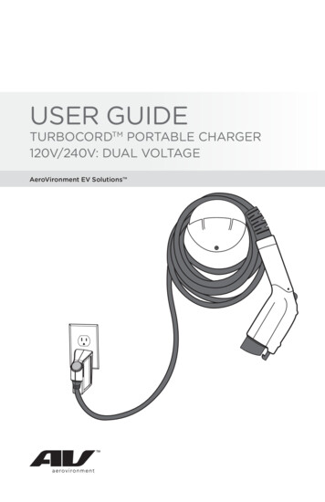
TURBOCORD CHARGER COMPONENTSCHARGE MODULE240 V ADAPTER CLIP240 V ADAPTERRelease buttonCHARGE COUPLER5
REQUIRED OUTLETSNOTEAny electrical socket should be checked by an electrician.120 VAC operation: a NEMA 5-15R wall outlet is required.NEMA 5-15R receptacle120 VNOTEA dedicated 120 VAC single phase circuit and a 15-amprated circuit breaker are required.208/240 VAC operation: a NEMA 6-20R wall outlet is required.NEMA 6-20R wall receptacle240 VNOTE6A dedicated 240 VAC split phase circuit or a 208 VACtwo phase circuit and a 20-amp rated circuit breaker arerequired.
SECTION 2USING YOURTURBOCORD CHARGER
KNOW YOUR INDICATOR LIGHTSThe indicator light on your dual voltage charger is the first thing you will noticewhen you are about to plug or unplug your vehicle. Before we get started, hereis a simple explanation of the indicators.CHARGE MODULE INDICATOR LIGHTSRed TROUBLEIndicator lightBlue STATUSIndicator lightBLUE: STATUSWhen plugged into the wall outlet, the BLUE STATUS Indicator illuminates tocommunicate that the charger is ready to use.RED: TROUBLEThe RED TROUBLE Indicator illuminates when the charger has detected anerror. If the RED TROUBLE Indicator is illuminated, the charger will not deliverpower to the vehicle. The error must be corrected before a charging cycle canbegin or continue. Refer to the Troubleshooting Guide in Section 3 for moreinformation.NOTEA momentary blink of the RED TROUBLE Indicator at firstplug-in to the wall socket is normal and functions as astartup safety check. This momentary blink is followed bythe solid BLUE STATUS Indicator and the RED TROUBLEIndicator turns off.WARNING8A constant or blinking RED TROUBLE Indicator indicatesan actual problem.
CHARGING YOUR VEHICLEYour charger is designed for easy charging in two modes – 120 VAC and 240VAC.120 VAC MODEWhen used WITHOUT the ADAPTER, the charger connects to a 120 V outletand charges your vehicle in “Level 1” charging mode. The Level 1, 120 VACcharge regimen takes longer to charge than the Level 2, 240 VAC mode;however 120 VAC wall outlets are typically more readily available.1. Insert the CHARGE MODULE into the appropriate 120V wall outlet.2. The BLUE STATUS Indicator on the CHARGE MODULE should be ON. Thismeans that the charger is ready to provide power to your vehicle.3. Plug the CHARGE COUPLER into your vehicle’s charging outlet until itclicks. If inserted properly, the BLUE STATUS Indicator will blink once. Oncelatched, the CHARGE COUPLER will not disengage unless the releasebutton is pressed manually.4. Automatic charge begins. Power will be delivered in accordance tovehicle demand. If the vehicle is charging, the BLUE STATUS Indicator willblink on and off approximately every two seconds. Always verify that thevehicle charging status indicator agrees.5. When fully charged, the BLUE STATUS Indicator light illuminates solidblue. Your vehicle has a “dashboard gauge” which can verify that thevehicle is fully charged. Refer to the vehicle owner’s manual to find thegauge location on your dashboard.6. Disconnect when the charge is complete by pressing the release buttonon the CHARGE COUPLER and removing it from the vehicle.9
240 VAC MODEWhen used WITH the ADAPTER, the charger can charge in Level 2, 240 VACmode. 21Charge ModuleAdapter ClipAdapter1. Snap the ADAPTER CLIP to the lower end of the CHARGE MODULE,lining up the appropriate symbols (and ) on the clip and module.2. Insert the CHARGE MODULE into the ADAPTER (make sure it is fullyinserted or the clip will not slide into the lock position). 3. Slide the ADAPTER CLIP up to the top of the CHARGE MODULE to lockin place.34. Insert the CHARGE MODULE with the attached ADAPTER into theappropriate 240 VAC wall outlet.5. The BLUE STATUS Indicator on the CHARGE MODULE should be ON. Thismeans that the charger is ready to provide power to your vehicle.6. Plug the CHARGE COUPLER into your vehicle’s charging receptacle until itclicks. Once latched, the CHARGE COUPLER will not disengage unless therelease button is pressed manually.7. Automatic charge begins. Power will be delivered in accordance tovehicle demand. If the vehicle is charging, the BLUE STATUS Indicator willblink on and off approximately every two seconds. Always verify that thevehicle charging status indicator agrees.8. When fully charged, the BLUE STATUS Indicator light illuminates solidblue. Your vehicle has a “dashboard gauge” which can verify that thevehicle is fully charged. Refer to the vehicle owner’s manual to find thegauge location on your dashboard.9. Disconnect when the charge is complete by pressing the release buttonon the CHARGE COUPLER and removing it from the vehicle.10
When plugging into an unfamiliar wall outlet, it is goodpractice to let the vehicle charge for several minutesbefore leaving it unattended, to ensure it is in factsupplying the expected AC charging power.NOTEThe RED TROUBLE Indicator will illuminate if not charging.The unit will turn OFF if breaker or infrastructure GFI istripped.MANUAL STOPTo safely stop charging at any time before charge completion, just press theCHARGE COUPLER release button and remove it from the vehicle.Charging will automatically and safely stop.BLUE STATUS Indicator remains ON solid.A NOTE ON AUTO-RESTARTThe Auto-Restart feature helps ensure that your vehicle will be charged andready for use when needed. A charge may be interrupted if an error is detected.Charging will resume once the error is no longer detected. The RED TROUBLEIndicator illuminates during an error condition.The exception to immediate Auto-Restart is when the interruption is due to acharger GFCI event. The charger will attempt to restart 15 minutes after a GFCIevent. After the fourth attempt to restart, the charger will shut down and theRED TROUBLE Indicator will stay ON.If the fault persists, do not continue to try to charge your vehicle. Contact AVCustomer Support.11
CHAPTER 3TROUBLE SHOOTING
TROUBLESHOOTINGPlease refer to this Troubleshooting Guide for possible solutions to commonerrors or difficulties with charging your vehicle using your portable charger.Do not attempt to repair or service the charger yourself.There are no user serviceable parts inside.NOTEA RED TROUBLE Indicator may be triggered by several sources, including thecharger, the utility service, or the vehicle. See Troubleshooting tips below.The RED TROUBLE Indicator turns on when the charger detects an errorwhether it is connected to your vehicle or not. With the RED TROUBLE Indicatoron, the dual charger will not deliver power to the vehicle. The error must becorrected before charging begins or resumes.ProblemBLUE STATUSIndicator does notilluminatePossible CauseNo power to unitSolution1. Check circuit breaker andother circuit loads.2. Try another wall outlet.3. Ensure charger module (andadapter if operating in 240VAC mode) is fully insertedinto the wall outlet.Vehicle will notchargeRED TROUBLEIndicator remainssolidCharger internalfailureContact AV Customer Supportfor assistance.Charge coupler isnot inserted intothe vehicle1. Inspect the charge coupler.Vehicle is not in astate to accept achargeVerify vehicle charge timer isset to permit charging. Refer tothe vehicle owner’s manual forcharge timer instructions.Communicationerror betweencharger andvehicleContact AV Customer Supportfor assistance.2. Remove the charge couplerfrom the vehicle, then reinsertit into the vehicle receptacleuntil it clicks.13
ProblemRED TROUBLEIndicator is blinkingrapidlyPossible CauseUtility faultSolution1. Disconnect the chargermodule from the wall outlet,then reconnect to the walloutlet.2. If the condition persists, havea qualified electrician inspectthe wall outlet ground circuitintegrity.3. Repair as required.Abovetemperature limitCases:1. Temperature istoo high. Thecharger willrestart chargingwhen it coolsdown.2. House/socketwiring may befaulty.1. Inspect charger module foroverheating (hot to the touch).a. Carefully unplug chargermodule from the wall outletand allow to cool.b. If the condition persists,contact AV CustomerSupport for assistance.2. Disconnect the charger (andadapter, if operating in 240VAC mode) from the walloutlet.3. Have a qualified electricianinspect the wall outlet andadapter integrity.a. Repair as required.RED TROUBLEIndicator is on solidwhen connected tovehicleVehicle problemContact your vehicle servicedepartment.Charger internalfailureContact AV Customer Supportfor assistance.RED TROUBLEIndicator is offand BLUE STATUSIndicator is on whenyou unplug fromvehicleRED TROUBLEIndicator is on solidNOT connected tovehicleRED TROUBLECharger trying toIndicator and BLUEresolve internalSTATUS Indicator are errorboth on14Charger will return to normaloperation within 1 minute. Ifproblem persists, contact AVCustomer Support for assistance.
APPENDIX
SPECIFICATIONSModelLine input power:Output power:Circuit breaker rating:Dual voltage120 VAC240/208 VAC12 amps continuous @ 120 VAC16 amps continuous @ 240/208 VAC15 amps @ 120 VAC20 amps @ 240 VACFrequency:60 HzPower draw at idleduring charging: 2 watts 4 wattsCable length:approximately 20 ft. (6.1 m)Weight:4 lb. (1.81 kg) – module0.2 lb. (0.09kg) – adapterTemperature –operating:Temperature –storing and transporting:-40 C to 50 C (-40 F to 122 F)-40 C to 70 C (-40 F to 158 F)Environmental rating:NEMA 6P (watertight)Vehicle – Dual voltage chargercommunication protocol:SAE J1772 compliantCharge coupler:SAE J1772 compliantDirection of charge:Grid to vehicleSpecifications are subject to change without notice.16
INSTALLING THE CABLE HANGERCABLE HANGER MOUNTING INSTRUCTION1. Choose a location to install the cable hanger. The hanger should be located in practical proximity to both the utilityservice and the location of your vehicle’s charge receptacle. Preferablymounted to a wall stud. Dry wall and masonry wall installations requirethe use of appropriate inserts.2. Measure up approximately 36” from the floor and mark the location.3. Drill out the preferred mounting holes through the back of the cable hangerusing a 7/32 -inch drill bit. 4. Using a Phillips Screwdriver, tighten the screws for the cable hanger.17
HIGH VOLTAGE WARNINGDANGERHigh voltage is present in your electric meter housingand power distribution service panel. Contact with highvoltage can cause death or serious personal injury.WARNINGDO NOT operate your charger with a damaged outputcable, charge coupler, adapter, or module. Visuallyinspect the output cable, charge coupler, adapter, andcharger module for damage before each use. If youdetect any damage, stop using the dual voltage chargerand contact AV Customer Support.WARNINGALWAYS position the charger output cable so that it willnot be driven over, stepped on, tripped over, or otherwisedamaged or stressed. To prevent personal injury anddamage to the charger, ALWAYS stow the charger andadapter on hanger or in stowage bag after use.WARNINGUse the charger only to supply power to electric vehiclesequipped with an SAE J1772 compliant vehicle receptacle.For more information, refer to the vehicle owner’s manual.NOTE18Disconnect the charger from the wall outlet beforecleaning it. To clean the charger, wipe it with a cleancloth dampened with water or a mild detergent solutionsuitable for use on automobile paint. Do not usechemicals or solvents. Do not submerge the charger.
STATE OF CALIFORNIA PROPOSITION 65 WARNINGSWARNINGThis product contains a chemical known to the Stateof California to cause cancer or birth defects or otherreproductive harm.FCC INFORMATIONThis device complies with Part 15 of the FCC Rules. Operation is subject to thefollowing two conditions: This device may not cause harmful interference.This device must accept any interference received, including interferencethat may cause undesired operation.This product has been designed to protect against Radio FrequencyInterference (RFI). However, there are some instances where high poweredradio signals or nearby RF producing equipment (i.e. digital phones, RFcommunications equipment, etc.) could affect operation.If you suspect your charger is receiving interference, take the following stepsbefore contacting Customer Support for service:1. Relocate nearby electrical appliances or equipment during charging.2. Turn off nearby electrical appliances or equipment during charging.Important! Changes or modifications to this product by anyone other than anauthorized service provider will void FCC compliance.SAFETY FEATURESThe charger is designed with your safety as the highest priority and includesthe following safety features to protect against the risk of electric shock: Service Ground Check: The charger constantly checks for the presenceof a service ground connection. If the service ground ever fails, the chargerRED TROUBLE Indicator turns ON and shuts down power to the vehicle. Thermal Event Sensor: Charger module senses out of ordinary thermalevents and will shut the unit down.19
GFCI Protection: The charger is equipped with a Ground Fault CircuitInterruption (GFCI) reaction system to protect against electric shock. If thecharger module detects an output ground fault, it will shut down power tothe output cable and illuminate the RED TROUBLE Indicator. Insulation: The charger module, adapter, cable assembly and chargecoupler are completely insulated (no exposed live parts) to protect againstelectric shock. Unintentional Disconnection: The charge coupler is designed tominimize unintentional disconnection. A pilot signal wire in the cableand charge coupler eliminates the possibility of electric shock when notconnected to a vehicle or if an unintended disconnect occurs during acharge. Disconnection during charging is safe.20
LIMITED WARRANTYTURBOCORD CHARGER LIMITED WARRANTYKEEP RECEIPT FOR WARRANTY CLAIMS.The AeroVironment, Inc. (AV) TurboCord EV charger is warranted to be free ofdefects in material and workmanship for a period of thirty-six (36) months fromthe date of original purchase.THIS IS THE SOLE AND EXCLUSIVE WARRANTY GIVEN BY AV WITH RESPECTTO THE TURBOCORD CHARGER. OTHER THAN EXPRESSED AND/OR IMPLIEDWARRANTIES REQUIRED BY APPLICABLE LAWS OR WHICH ARE REQUIREDTO EXTEND FOR A LONGER PERIOD, THERE ARE NO WARRANTIESTHAT EXTEND BEYOND THIS LIMITED WARRANTY AND ANY REQUIREDWARRANTIES ARE LIMITED IN DURATION TO THE WARRANTY PERIOD.To the extent permitted by applicable laws: (a) AV’s total warranty expensewith respect to the charger is limited to a maximum of the original purchaseprice of the charger as applicable to a warranty claim; (b) AV’s liability underthis warranty shall be limited to the repair or replacement, at AV’s option, ofdefective component parts; and (c) AV will not be liable for repair, replacementor service call costs for the charger not covered by this warranty, which shall bethe responsibility of the purchaser.This warranty shall be voided by damage or excessive wear to the chargercaused by abnormal operating or environmental conditions (including exposureto acid, chemical fumes, metallic dust or extreme temperatures), accident,abuse, damage, misuse, vandalism, unauthorized alteration or repair, utilitysurges, or if the charger was not operated, serviced or maintained in strictcompliance with the charger User’s Manual and other printed instructionsprovided by AV and applicable building codes. Any evidence of an attempt todisassemble or reverse engineer the charger will void this warranty.21
INDEXAadapter. 3, 5, 10, 13, 14,16, 18, 20adapter clip. 5, 10auto-restart. 11BBLUE STATUS indicator. 8,9, 10, 11, 13, 14Ccharge coupler. 5, 9, 10, 11,13, 18, 20charge module. 5, 8, 9, 10circuit breaker. 3, 6, 13, 16components. 5customer support. iDdedicated circuit. 3document number. iEelectric shock. 3, 4,19, 20environmental rating. 16Ffeatures. 3, 19GGFCI. 11, 20Hhanger. 17, 18Iindicator light. 8, 9, 10insulated. 2022Mmanual stop. 11Ooutlet. 3, 4, 6, 8,9, 10, 11, 13, 14output ground. 20Ppilot signal wire. 20RRED TROUBLE indicator. 8,11, 13, 14, 19, 20release button. 5, 9, 10, 11SSAE J1772. 3, 16, 18safety features. 19serial number. iservice ground. 19STATUS indicator. 8, 9,10, 13, 14Ttemperature. 16, 21TROUBLE indicator. 5, 8, 11,13, 14, 19, 20Wwall receptacle. 6warranty. 21weight. 16
AeroVironment EV SolutionsCustomer Support1-888-833-2148evscs@avinc.comCorporate HeadquartersAeroVironment, Inc.EV Solutions 181 W. Huntington Drive, Suite 202Monrovia, CA 91016Corporate phone: 626-357-9983or 3 Rev 1
begin or continue. Refer to the Troubleshooting Guide in Section 3 for more information. A momentary blink of the RED TROUBLE Indicator at first plug-in to the wall socket is normal and functions as a startup safety check. This momentary blink is followed by the solid BLUE