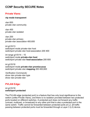
Transcription
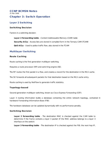
CCNP BCMSN Notes31 Mar 2008Chapter 3: Sw itch OperationLayer 2 SwitchingSw itching DecisionFactors in a switching decision:Layer 2 forwarding table - Content Addressable Memory (CAM) tableSecurity A CLs - Access lists are stored in compiled form in the Ternary CAM (TCAM)QoS A CLs - Used to police traffic flow, also stored in the TC AMMultilayer SwitchingRoute C achingRoute caching is the first generation multilayer switching.Requires a route processor (RP) and switching engine (SE).The RP routes the first packet in a flow, and creates a record for the destination in the MLS cache.The SE forwards all subsequent packets for that destination based on the MLS cache entry.Route caching is used by NetFlow to generate traffic statistics.Topology-basedSecond generation multilayer switching, known as Cisco Express Forwarding (CEF).Layer 3 routing information builds a database containing the entire network topology, contained inhardware Forwarding Information Base (FIB).The hardware database can be updated dynamically with no performance penalty.Sw itching DecisionLayer 2 forwarding table - The destination MAC is checked against the C AM table todetermine if the frame contains a layer 3 packet (if the MAC address belongs to a layer 3interface on the switch)Layer 3 forwarding table - The destination IP is checked against the FIB; the next-hop IP,
next-hop MAC , and egress port (and VLAN) are returnedSecurity A CLs - Same as in L2QoS A CLs - Same as in L2Multilayer Sw itching ExceptionsPackets which require processing cannot be forwarded by C EF:ARPIP packets requiring a response from the routerIP broadcasts relayed as unicasts (via IP helpers)Routing protocol updatesC DPIPX routing protocol and service advertisementsPackets needing encryptionPackets requiring Network Address Translation (NAT)Other non-IP and non-IPX packetsSwitching TablesC ontent Addressable Memory (C AM)The C AM table stores MAC -to-port/VLAN bindings on all C atalyst switches.C AM is updated with each frame received.The C AM table can be inspected with show mac address-table.Ternary C ontent Addressable Memory (TC AM)TC AMs facilitate the processing of inbound and outbound security and QoS AC Ls in hardware.Physically separate memory allows AC Ls checks to be done in parallel with forwarding decisions.The Feature Manager (FM) compiles AC Ls into machine code and inserts them into the TC AM.The Switching Database Manager (SDM) allows for configuration and repartitioning of the TC AM.TC AMs operate with values, masks, and results:
V alue - 134-bit value composed of source and destination addresses and other protocolinformation; format is dependent on AC L typeMask - 134-bit mask in the same format as its complement value; used to mark bits whichmust be matched in the valueResult - A numerical value which represents which action should be taken nextLayer 4 port ranges are stored in Logical Operation Unit (LOU) registers.Chapter 4: Sw itch Port ConfigurationIEEE standards:802.3 - Ethernet802.3u - Fast Ethernet802.3z - Gigabit Ethernet802.3ab - Gigabit Ethernet over copper (1000Base-T)802.3ae - 10 Gigabit EthernetGigabit Ethernet was the result of merging IEEE 802.3 Ethernet and ANSI X3T11 FibreC hannel.GBIC /SFP -TGigaStack (C isco Proprietary)Fiber modules take the Rx fiber on the left and Tx on the right (when facing the module).Interface error disabling can be tuned in global config:Chapter 5: VLANs and TrunksThe normal range allows for VLANs 1 - 1005; IEEE 802.1Q expands this to 1 - 4095.
VTP version 1 and 2 only support VLANs 1 - 1005. VTPv3 will support extended VLANs but isn't availableyet.Dynamic VLANs can be configured by a VLAN Membership Policy Server (VMPS).Trunk types:Inter-Switch Link (ISL) - C isco proprietary; 26-byte headerIEEE 802.1Q - Open standard; 4-byte headerIEEE 802.3ac extends the Ethernet MTU to 1522 to account for the 4-byte 802.1Q header.Trunk configuration:Chapter 6: VLAN Trunking ProtocolVTP modes:Client - Rely on VLAN information advertised by a server; no local configuration possibleServer - Have full control over VLAN creation and modification for the VTP domainTransparent - Does not participate in VTP but will forward advertisementsVTP advertisements:Summary - Sent every 300 seconds or whenever a change occursSubset - Sent after a summary advertisement when a change occurs; these provide moredetail to reflect the change that was madeA dvertisement Request - Issued by clients to request VLAN informationPruning Request - Sent from clients to servers to announce active VLANs; inactive VLANsmay be pruned from the trunkVTP configuration:Switch(config)# vtp mode {server client transparent}
Switch(config)# vtp version {1 2}Switch(config)# vtp domain domain Switch(config)# vtp password password VTP pruning can be enabled with vtp pruning.Verification:show vtp statusshow vtp countersChapter 7: Aggregating Sw itch LinksEtherChannel Load BalancingEtherC hannel distributes load across multiple physical links by examining between one and three loworder bits of an arbitrary address. XOR is used when multiple addresses are examined.Address types eligible for examination:Source and destination MA C - src-mac (default for L2 channels), dst-mac, orsrc-dst-macSource and destination IP - src-ip, dst-ip, or src-dst-ip (default for L3 channels)Source and destination L4 port - src-port, dst-port, or src-dst-port (C atalyst6500/4500 only)Port channel load balancing is configured globally:EtherChannel NegotiationPort Aggregation Protocol (PAgP)PAgP is C isco proprietary.Port channels are configured as desirable (active) or auto (passive).Addition of the non-silent parameter will ensure the etherchannel will not be formed without receivingPAgP packets from the neighbor.
C onfiguring PAgP:Link Aggregation C ontrol Protocol (LAC P)LAC P is defined in IEEE 802.3ad.The switch with the lowest priority designates which interfaces participate in the etherchannel.Interfaces are configured as active or passive.lacp port-priority priority is used to assign an LAC P priority to individual ports.Lower-priority interfaces beyond the eight-port limit for a single channel will be designated as standbyinterfaces should one of the higher-priority links fail.C onfiguring LAC P:StaticEtherC hannel interfaces can be set to on, forming a permanent etherchannel with no autonegotiationprotocol (neither PAgP or LAC P is used).Troubleshootingshow etherchannel summaryshow etherchannel portshow etherchannel load-balanceshow {pagp lacp} neighbor
Chapter 8: Traditional Spanning Tree ProtocolSTP is defined in IEEE 802.1D.BPDUsSTP messages are carried by Bridge Protocol Data Unit (BPDU) frames; BPDUs are multicast to01:80:c2:00:00:00.BPDU types:Configuration - Used for spanning-tree computationTopology Change Notification (TCN) - Used to announce changes in the networkC onfiguration BPDUs are sent out every port every two seconds by default.Root Bridge ElectionA root bridge is elected to serve as a common reference point for the topology.A switch's bridge ID is composed of two parts:Bridge priority (2 bytes) - Administratively set; defaults to 32,768 (0x8000)MA C address (6 bytes) - One of the switch's MAC addressesAll switches assume they are the root bridge at boot. The actual root bridge is the switch with the lowestbridge ID.C onfiguration BPDUs are only generated by the root bridge; all other bridges insert their own sender IDand relay them.Root Port ElectionAll non-root switches must designate a single interface as the root port (the port with the best path tothe root bridge).All interfaces are assigned an 8-bit cost derived from their speed.Port costs:Bandwidth C ost4 Mbps25010 Mbps100
16 Mbps6245 Mbps39100 Mbps 19155 Mbps 14622 Mbps 61 Gbps410 Gbps2The port with the lowest path cost to the root bridge is designated as the root port.The root path cost noted in a BPDU is incremented by the cost assigned to the port on which it wasreceived.Designated Port SelectionIf multiple switches reside on a segment, the one with the lowest root path cost has the designatedport; the other ports will be set to blocking.Designated port selection process:1. Lowest root bridge ID2. Lowest root path cost3. Lowest sender bridge ID4. Lowest sender port IDSTP StatesDisabled - ShutdownBlocking - The first state when an interface comes up; only receives BPDUs; indefinitedurationListening - C an send and receive BPDUs; able to participate in STP; duration specified byforward delay timerLearning - C an send and receive BPDUs and learn MAC addresses; duration specified byforward delay timerForwarding - Normal operation; indefinite durationSTP TimersHello Time - The rate at which configuration BPDUs are advertised by the root bridge(default is 2 seconds)
Forward Delay - Length of time a port spends in both the listening and learning states(default is 15 seconds)Max A ge - Life of the most recent BPDU advertised from the root bridge (default is 20seconds)Timers can be individually adjusted manually on the root bridge, or automatically adjusted by modifyingthe network diameter (number of switch hops which extend from the root).STP TypesCommon Spanning Tree (CST) - Defined in 802.1Q; one tree for all VLANsPer-V LA N Spanning Tree (PV ST) - C isco proprietary; one tree per VLANPer-V LA N Spanning Tree Plus (PV ST ) - PVST featuring compatibility with C ST BPDUsChapter 9: Spanning Tree ConfigurationRoot Bridge ConfigurationThe root bridge should be positioned centrally in the network to ensure the spanning tree forms in apredictable manner.Two bridge ID formats are available:802.1D Standard - 16-bit priority unique MAC address for the VLAN802.1t Extended - 4-bit priority multiplier 12-bit VLAN ID non-unique MAC addressThe extended ID format is enabled by default, or with spanning-tree extend system-id.An extended system ID priority must be a multiple of 4096.There are two ways to designate the root bridge.Setting a static priority:Allowing the switch to decide its own priority relative to other switches on the network:
Port Cost and ID TuningTo manually configure the cost for a port (and override the default cost associated with its speed):The port ID consists of an 4-bit port priority (default value is 128) and a 12-bit port number.To manually configure the priority of a port:Tuning Spanning-Tree ConvergenceManually configuring STP timers:Timers can also be automatically adjusted when designating an automatically determined bridge priority(via the diameter parameter):Redundant Link ConvergencePortFast - Applied to access ports to allow fast establishment of connectivityUplinkFast - Enables fast failover to an alternate uplink toward rootBackboneFast - Enables fast convergence in the core after a topology changePortFastC an be enabled globally:Or, per-interface:
UplinkFastC an only be enabled on switches which do not act as transit to root (and are not root).Enabled globally, for all ports and VLANs:The optional max-update-rate (default 150) specifies how fast to flood out spoofed multicast framesfrom sources in the C AM so that upstream switches see them on the new link.BackboneFastBackboneFast allows a switch to respond to inferior BPDUs (BPDUs from a new switch claiming to beroot) immediately, instead of waiting for the Max Age timer to expire.Root Link Query (RLQ) protocol requests are sent out to see if upstream switches have a path to root.BackboneFast is enabled globally:If enabled, BackboneFast should be enabled on all switches in the domain, due to its reliance on RLQ.Troubleshooting Spanning-Treeshow spanning-tree [detail summary .]Chapter 10: Protecting the Spanning Tree Protocol TopologyRoot GuardIf a switch with a lower bridge ID enters the network, it can preempt the current STP root.Root guard can be enabled on an interface to prevent it from becoming a root port:
Root guard will affect all VLANs on the port.Ports disabled by root guard can be viewed with show spanning-tree inconsistentports.BPDU GuardBPDU guard automatically places an interface in the error-disabled state upon receipt of a BPDU.BPDU guard can be enabled globally or per interface:Loop GuardLoop guard prevents a blocked port from transitioning to the forwarding state if it stops receivingBPDUs. Instead, the port is placed in the loop-inconsistent state and continues to block traffic.Loop guard operates per VLAN, and can be enabled globally or per interface:Unidirectional Link Detection (UDLD)UDLD can detect link failures which do no explicitly shutdown the interface (such as a unidirectional fiberlink or failed intermediate media converter).UDLD transmits frames across a link at regular intervals, expecting the distant end to transmit themback.The default UDLD message timer is 7 or 15 seconds (depending on the platform), allowing it to detect aunidirectional link before STP has time to transition the interface to forwarding mode.UDLD has two modes of operation:Normal mode - UDLD will notice and log a unidirectional link condition, but the interface isallowed to continue operating.A ggressive mode - UDLD will transmit 8 additional messages (1 per second); if none ofthese are echoed back the interface is placed in the error-disabled state.UDLD can be enabled globally for all fiber interfaces, or per-interface:
The UDLD message time can be from 7 to 90 seconds.UDLD will not consider a link eligible for disabling until it has seen a neighbor on the interface already.This prevents it from disabling an interface when only one end of the link has been configured to supportUDLD.udld reset can be issued in user exec to re-enable interfaces which UDLD has disabled.BPDU FilteringBPDU filter can be enabled globally or per-interface to effectively disable STP:Chapter 11: Advanced Spanning Tree ProtocolRapid STP (RSTP)RSTP was developed to provide a faster converging alternative to STP, and is defined in IEEE 802.1w.Like STP, RSTP can be applied as a single instance or per VLAN.A root is elected by lowest bridge ID, as in 802.1D STP.RSTP provides its own set of port roles:Root port - Same as in 802.1DDesignated port - Same as in 802.1DA lternate port - A port with an alternate, less desirable path to rootBackup port - A port which provides an alternate, less desirable path to a segment whichalready has a designated portRSTP defines port states based on what action is taken on incoming frames:Discarding - Frames are dropped, no addresses are learned (replaces 802.1D disabled,blocking and listening states)Learning - Frames are dropped, but addresses are learned
Forwarding - Frames are forwardedRSTP defines a new version of BPDU (v2) which is backward-compatible with 802.1D.BPDUs are sent out from every switch at hello time intervals; a neighbor is assumed down if threeintervals are missed.If an RSTP switch detects a traditional (version 0) BPDU on a port, that port changes to operate in802.1D mode.Port types:Edge port - A port to which a single host connects; identified by enabling PortFast; loses itsedge status upon receipt of a BPDURoot port - The port with the best path to root; alternates can be identified as wellPoint-to-point port - A designated port connected directly to another switch; onlyfull-duplex ports are eligible by defaultRSTP SynchronizationAll non-edge ports begin in the discarding state.Proposal messages are used to determine the root port of a segment based on bridge priorities.When a switch receives a proposal message on a port, it moves all other non-edge ports to thediscarding state until it sends an agreement to the sender of the proposal.When an agreement is reached, the ports on both ends of the link begin forwarding.This method of proposal/agreement handshakes allows the synchronization process to complete muchfaster than traditional STP, as no timers are needed.Topology change BPDUs are sent only when a non-edge port transitions to forwarding.RSTP C onfigurationRSTP is enabled by configuring Rapid PVST:Half-duplex links to other switches can be administratively designated as point-to-point links:
Multiple Spanning Tree (MST)MST was developed to offer a middle ground between C ST (one instance for all VLANs) and PVST (oneinstance for each VLAN).An MST region is defined by several attributes:C onfiguration name (32 characters)C onfiguration revision number (16-bit)Instance-to-VLAN mapping table (up to 4096 entries)All attributes must match for two switches to belong to the same region.An MST region is seen as a single virtual bridge by an outside C ST, and runs an Internal Spanning Tree(IST) inside.Up to 16 MST Instances (MSTIs) numbered 0 through 15 run inside an MST region; MSTI 0 is the IST.Additional MSTIs can be created and have VLANs assigned to them.MST C onfigurationEnabling MST:C reating an MST region:View pending changes before they are applied:
Chapter 12: Multilayer Sw itchingInterfaces on multilayer switch are designated as switch ports (layer 2) with switchport or routed ports(layer 3) with no switchport.Switched Virtual Interfaces (SVIs) can be defined to provide a routed interface to a VLAN.Cisco Express Forwarding (CEF)Traditional multilayer switching ("route once, switch many", also known as NetFlow switching or routecache switching) was done through the combination of a route processor and a switching engine.C EF is the second generation of multilayer switching, and is enabled by default in hardware whichsupports it.C EF operation relies on two components working in tandem: the layer 3 engine (routing) and the layer 3forwarding engine (switching).The layer 3 forwarding engine contains the Forwarding Information Base (FIB) and its Adjacency Table.Forw arding Information Base (FIB)The FIB is an optimized copy of the routing table, with more-specific routes listed first.Each entry in the FIB has layer 2 and 3 next-hop addressing information associated with it.FIB entries can be examined with show ip cef.Packets meeting certain conditions cannot be C EF-switched and will be punted to the layer 3 engine fortraditional software routing:Expired TTLMTU exceededIC MP redirect requiredUnsupported encapsulation typeC ompression and/or encryption is necessaryAn AC L log entry must be generatedAccelerated CEF (aCEF) can be implemented in some hardware to cache portions of the FIB on eachline card.Distributed CEF (dCEF) stores the entire FIB on all capable line cards.
Adjacency TableThe adjacency table is the portion of the FIB which contains layer 2 next-hop information (MACaddresses which correspond to the layer 3 next-hop addresses).Similar to how the FIB is built from the routing table, the adjacency table is built from the ARP table.Adjacency information can be examined with show adjacency.Adjacency table entries with missing or expired layer 2 addresses are placed in the CEF glean state;packets must be punted to the L3 engine so an ARP request/reply can be generated.When a route is placed in the glean state, incoming packets will be dropped for up to two seconds as theswitch awaits an ARP reply.Other adjacency states include:Null - Represents a null interface (black hole)Drop - Indicates packets cannot be forwarded to the destination and should be droppedDiscard - An AC L or other policy mandates that packets be droppedPunt - Further processing is required by the layer 3 enginePacket Rew riteThe packet rewrite engine reconstructs the incoming packet with the appropriate next hop addressinformation.Fields rewritten include:Layer 2 destinationLayer 2 sourceIP TTLIP C hecksumLayer 2 frame checksumFallback BridgingNon-IP protocols are not supported by C EF.Each SVI carrying nonroutable traffic can be assigned to a bridge group and bridged transparently,separate from normal L2 switching.
A special type of STP known as VLAN-bridge is run on these bridge groups.Fallback bridging must be manually configured:Verifying Multilayer Switchingshow interface switchport ("Disabled" verifies layer 3 operation)show ip cef [detail]show bridge groupChapter 13: Router, Supervisor, and Pow er RedundancyHot Standby Router Protocol (HSRP)HSRP is C isco proprietary, but defined in RFC 2281.HSRP routers multicast to the all-routers address 224.0.0.2 on UDP port 1985.HSRP group numbers (0 - 255) are only significant to an interface.HSRP group configuration:HSRP virtual interfaces are assigned a MAC in the range 0000.0c07.acXX where the last 8 bitsrepresent the standby group.Router ElectionHSRP priority ranges from 0 to 255; default is 100.The highest priority wins; highest IP wins a tie.HSRP interface states:
DisabledInitListenSpeakStandbyActiveThe default hello timer is 3 seconds; holddown timer is 10 seconds.Timers can be adjusted:By default a router with higher priority cannot preempt the current active router; this can be allowed:minimum defines the time the router must wait after it becomes HSRP-capable for the interface.reload defines the time it must wait after reloading.AuthenticationC isco devices by default use the plaintext string "cisco" for authentication.Plaintext or MD5 authentication can be usedC onceding the ElectionA router can be configured to withdraw from active status if one or more of its other interfaces fail:The router's priority will be decremented by the associated value (default 10) if the tracked interfacefails.If another router now has a higher priority and has been configured to preempt, it will take over as the
active router for the group.Verificationshow standby [brief] [interface]Virtual Router Redundancy Protocol (VRRP)Standards-based alternative to HSRP, defined in RFC 2338.VRRP refers to the active router as the master router; all others are in the backup state.VRRP virtual interfaces take their MAC from the range 0000.5e00.01XX where the last eight bitsrepresent the group number.VRRP advertisements are multicast to 224.0.0.18, using IP protocol 112.VRRP advertisements are sent in 1-second intervals by default; backup routers can optionally learn theinterval from the master router.VRRP routers will preempt the master by default if they have a higher priority.VRRP is unable to track interfaces and concede an election.VRRP C onfigurationVRRP configuration is very similar to HSRP configuration:Verificationshow vrrp [brief]Gateway Load Balancing Protocol (GLBP)GLBP is C isco proprietary, and acts like HSRP/VRRP with true load-balancing capability: all routers in agroup forward traffic simultaneously.GLBP group numbers range from 0 to 1023. Priorities range from 0 to 255 (default is 100).
IP address(es), router preemption, and hello/hold timers (default 3/10 seconds) can be configured likefor HSRP:Timers only need to be configured on the AVG; other routers will learn from it.Active Virtual Gatew ay (AVG)The AVG has the highest priority in the GLBP group (or the highest IP address in the event of a tie); itanswers all ARP requests for the group's virtual IP address.Active Virtual Forw arder (AVF)All routers sharing load in GLBP are AVFs.If an AVF fails, the AVG reassigns its virtual MAC to another router.Two timers are used to age out the virtual MAC of a failed AVF:Redirect timer (default 600 seconds) - Determines when the AVG will stop responding toARP requests with the MAC of the failed AVFTimeout timer (default 4 hours) - Determines when the failed AVF is no longer expected toreturn, and its virtual MAC will be flushed from the GLBP groupC onfiguring the timers:AVFs are assigned a maximum weight (1-254; default is 100).Interfaces can be tracked and the AVF's weight adjusted when interfaces go down:When the upper or lower threshold is reached, the AVF enters or leaves the group, respectively.
Load BalancingUp to four virtual MAC s can be assigned by the AVG.Traffic can be distributed among AVFs using one of the following methods:Round robin (default) - Each new ARP request is answered with the next MAC addressavailable; traffic is distributed evenly among AVFsWeighted - AVFs are assigned load in proportion to their weightHost-dependent - Statically maps a requesting client to a single AVF MACC onfiguring load balancing:Verificationshow glbp [brief]Switch Chassis RedundancyRedundant supervisor modes:Route Processor Redundancy (RPR) ( 2 minutes) - The standby supervisor is onlypartially initialized; when the active sup fails, the standby must reload all modules and finishinitializing itself.Route Processor Redundancy Plus (RPR ) ( 30 seconds) - The standby supervisorboots but does not operate; when the active sup fails, the standby can take over withoutreloading the modules.Stateful Switchover (SSO) ( 1 second) - C onfiguration and layer 2 information are storedon both supervisors; the standby sup takes over immediately.C onfiguring supervisor redundancy:If configuring redundancy for the first time, it must be configured manually on both supervisors.Redundant operation can be verified with show redundancy states.
Non-Stop Forw arding (NSF)When a standby supervisor takes over, it must populate its RIB; this can be achieved quickly with C isco'sproprietary NSF. NSF-aware neighbors provide routing information to quickly populate the new RIB.BGP, EIGRP, OSPF, and IS-IS support NSF, but it must be enabled through manual configuration underthe relevant protocol:Redundant Power SuppliesSwitches with multiple power supplies can operate in one of two power modes:Combined mode - The load for a single power supply may be exceeded; does not provideredundancy.Redundant mode (default) - Load is shared but may not exceed the output of a singlepower supply.C onfiguring power mode:Power may be administratively removed from or applied to individual modules:Verification:show power [redundancy-mode status available used total]show power inline - Displays power drawn from PoE interfacesChapter 14: IP TelephonyPower Over Ethernet (PoE)Two solutions exist to supply PoE:Cisco Inline Power (ILP) - C isco proprietary solution developed before IEEE 802.3af
IEEE 802.3af - StandardIEEE 802.3afAn 802.3af PoE switch applies a small voltage across the wire and checks for 25K Ohm resistance todetermine if a PoE device is connected.Depending on the resistance presented at differing test voltages, the switch can determine which powerclass a device belongs to:Class 0 - 15.4W (default)Class 1 - 4.0WClass 2 - 7.0WClass 3 - 15.4WClass 4 - Reserved for future useThe power class determines how much of the switch's power budget is allocated to the interface.Power is supplied over pairs 1,2 and 3,6 or pairs 4,5 and 7,8.C isco ILPA C isco ILP switch transmits a 340kHz test tone on the Tx pair to detect a PoE device; if a C iscoILP-capable device is present, the tone will be echoed back.Power is supplied over pairs 1,2 and 3,6.C isco ILP detects a device's power requirement via C DP.C onfiguring PoEAll capable switch ports will attempt PoE by default (auto).PoE can be verified with show power inline.Voice VLANsTrunks to IP phones are automatically negotiated by Dynamic Trunking Protocol (DTP) and C DP.C onfiguring a voice VLAN:
none (default) - No trunk is formed; voice and data traffic traverse the same access VLANvlan - Forms an 802.1Q trunk with designated voice VLAN and native (access) VLAN fordata; 802.1p C oS bits in 802.1Q header provide independent QoSdot1p - Forms an 802.1Q trunk with voice in VLAN 0, data in native VLAN; 802.1p C oS bitsuseduntagged - Forms an 802.1Q trunk with voice and data both untagged; 802.1p is not usedVoice QoSQoS models:Best-Effort Delivery - No QoSIntegrated Services Model - Bandwidth is reserved along a path via Resource ReservationProtocol (RSVP); defined in RFC 1633Differentiated Services Model - QoS is handled dynamically per-hop, based on protocolheaders and defined policiesLayer 2 DiffServ Q oSLayer 2 frames transported in a trunk receive a designated Class of Service (CoS) value in the trunkheader (802.1p bits).802.1Q native VLAN frames are not tagged and thus are treated with the default C oS.ISL trunks duplicate the same priority scheme as 802.1p.Layer 3 DiffServ Q oSThe IP Type of Service (ToS) header field originally defined a 3-bit IP precedence value and a 4-bit ToSvalue.The DiffServ QoS model reinterprets this field as a 6-bit Differentiated Services Control Point (DSCP),composed of a 3-bit class selector and a 3-bit drop precedence.C lass 0 - Best effort forwardingC lasses 1-4 - Assured Forwarding (AF) with drop preferencesC lass 5 - Expedited Forwarding (EF)C lasses 6-7 - Network control
Configuring a Trust Boundarymls qos trust device cisco-phone enables QoS trust only when a C isco IP phone is detected viaC DP.switchport priority extend instructs the phone on how the trust boundary should be extended to aconnected PC . The cos option overwrites all frames with the given C oS value.Auto-QoSAuto-QoS was developed to ease implementation of QoS.Auto-QoS is a macro which automatically performs the following configurations:Enabling QoSC oS-to-DSC P mappingIngress and egress queue tuningStrict priority queues for egress voice trafficEstablishing an interface QoS trust boundaryC onfiguring Auto-QoS on an interface:Any existing QoS configuration must be completely removed from an interface before Auto-QoS can beapplied.debug auto qos can be enabled before applying Auto-QoS to monitor the explicit commands beingissued by the macro.Verifying QoSshow mls qos interface interface show interface interface switchportChapter 15: Securing Sw itch Access
Port SecurityPort security can be used to restrict which or how many hosts connect to a switch port:Violation actions:protect - The port continues to function without logging a violation, but frames fromviolating MAC addresses are dropped.restrict - As with protect mode, frames from violating MAC addresses are dropped, butthe violation is logged.shutdown - The port is transitioned to the error-disabled state, and no traffic is accepted.IEEE 802.1xExten
CCNP BCMSN Notes 31 Mar 2008 Chapter 3: Switch Operation Layer 2 Switching Switching Decision Factors in a switching decision: Layer 2 forwarding table - Content Addressable Memory (CAM) table Security ACLs - Access lists are stored in compiled form in the Ternary CAM (TCAM) QoS AC


