Transcription
Flares in refineries andchemical plantsIndustry Standards and US emissionsregulationsAFRC – Houston, Tx, September 19-20, 2011
Presentation Contentsn International Standards Related to Flaringn n n Elevated Steam Assisted Flare – EfficiencyConsiderationsn n n n n Important Operating AspectsParameters Affecting Flare Design and OperationPractical ConcernsMaintenance and OperationUSA Flare Regulatory Specific Requirementsn n CurrentPlanned changesFederal and State developmentsExcluded from this presentation - air-assist flares,enclosed flares, and ground flares.2
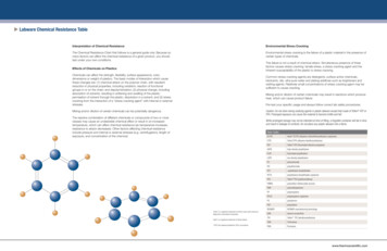
STANDARDIZATION BODIES - RELATIONSHIPSRe Internationalcog Regionalnise National ANSIdIndustryCompaniesAPIISO / IECJapanetc.ASMEOPERATORSLiaisonOGPVienna AgreementCEN /CENELECBSIOtherEuropeanEEMUA UKOOACONTRACTORSSUPPLIERSCredit: Shell Oil3
International Standards Related to Flaringn ISO 23251 / API 521 “Pressure Relieving and De-Pressuring Systems”n n n n Specifies requirements and gives guidelines for examining the principalcauses of overpressure and determining individual relieving rates.Aids in the selection and design of disposal systems appropriate for therisks and circumstances in various installations.Includes component parts e.g. flares, piping, vessels, and vent stacks.ISO 25457 / API 537 “Flare Details for General Refinery andPetrochemical Service”n n Describes the mechanical design, operation, and maintenance ofelevated, multi-burner staged, and enclosed flares.Supplements the practices set forth in ISO 23251 / API 5214
ISO 25457 / API 537 “Flare Details for GeneralRefinery and Petrochemical Service”n n n n This Standard, first published in 2003, supplements rather than duplicatesthe practices set forth in ISO 23251 / API 521.When API 537 was written, manufacturers’ and operating companies’ inputwas sought so the final document reflected prevailing technology expertise.API 521 Task Force members worked together with the API 537 membersto write this Flare Details Standard.API 537 was revised and reissued as ISO 25457/API 537 in 2008. Therevision reflected prevailing worldwide technology expertise from the 150plus ISO countries who employ this StandardThis Standard provides details regarding the mechanical design, operation,and maintenance of elevated, multi-burner staged, and enclosed flares.n n n Elevated FlaresMulti-burner Staged FlaresEnclosed Flares5
Specifying flare requirements usingISO 25457 / API 537n n Effective communication of flare design information is necessarybetween users, process designers, engineers and constructors, andflare equipment designer/supplier.To facilitate that communication, ISO 25457 / API 537 containsdetailed flare data sheets to specify requirements for elevated orenclosed flares.n n These data sheets are designed to provide a concise but thoroughdefinition of the flare system and its performance.These data sheets cover both mechanical and process aspects of flaredesign. Those using the data sheets are referred to ISO 23251 forprocess information. The combination of ISO 23251 and this InternationalStandard provides a broad source of information for those interested inflares.6
ISO 23251 / API 521 “Pressure Relieving andDe-Pressuring Systems”n n n n n Flare requirements are a portion of this 200 page document.This Standard is intended for use primarily in oil refineriesIt is also applicable to petrochemical facilities, gas plants, liquefied naturalgas (LNG) facilities, and oil and gas production facilities.It is referenced by many non petroleum companies in their engineeringstandards dealing with pressure relief and flare systems.When published as a co-branded standard in January 2007, ISO23251/API521 was the 5th Edition of API 521.7
ISO 23251/API 521 “Pressure-relieving andDe-Pressuring systems”n Combustion and destruction efficiency of the flare gases are not covered by thisStandard.n n n n The criteria address flare smoking, noise, and thermal radiation.Steam to hydrocarbon ratios provide a general guideline for the quantity of steamrequired in order to promote smokeless burning at average flow rates.The Standard qualifies the suggested steam amount with the following statement: "Thegiven values provide a general guideline for the quantity of steam required. Consult theflare vendor for detailed steam requirements."The Standard states that “proprietary tip designs are available from variousmanufacturers which offer unique steam injection methods and varying resultant steamefficiencies”.8
ISO 23251/API 521 “Pressure-relieving and DePressuring systems” – Changes being maden n States that API 521/ISO 23251 steam to hydrocarbon ratios are notrelated to flare combustion efficiencyStates that combustion efficiency is a function of several parametersincluding flare tip design, flare composition, flare flow rates(turndown), steam injection types, and more.9
API 521 Flare Focus TeamTo develop a consensus position regarding factors thataffect flare efficiency, major flare vendors formed anAPI 521/ISO 23251 Focus TeamTeam MembersPaul Eichamer – Coordinator – ExxonMobil (retired)Brian Duck – CallidusDrue Smallwood – CallidusJim Franklin – John ZinkZach Kodesh – John ZinkKevin Leary – John ZinkJohn Straitz – NAOScot Smith – ZeecoJohn Soderstrom - Zeeco10
Elevated Steam Assisted Flare –Efficiency Considerationsn n n n Hydrocarbon emissions are related to the degree of combustion.Completeness of combustion is governed by flame temperature, degree of turbulent mixingof the components with air, and availability of oxygen.Factors affecting combustion and destruction efficiency in an elevated steam-assist flare areinter-related.Factors that most impact elevated steam-assisted flare efficiency include:n n n n n n n Steam assisted flare tip configuration (The geometry and design of the flare tip.)Flare gas composition (The net heating value of the flare gas, the amount of diluent present, the type ofdiluent, i.e. CO2, N2, etc., the presence of hydrogen, the speed of reaction for individual constituents, thepresence of liquids in the flare gas.)Control of steam flowThe amount of turndown at which the flare is operating (Affects mixing of the air with the flare gas.)Wind speed (Higher and variable wind speeds could adversely affect a flare’s combustion/destructionefficiency.)Flare pilot design including type, heat release, and number of pilotsEquipment condition11
Important Operating Aspects of Flaresn Well-operated flares combust a high percentage of hydrocarbon molecules by:n n n n Ensuring hydrocarbon is heated to a sufficient temperature to initiate combustionMaintaining proper exit velocitiesMaking oxygen available for each hydrocarbon moleculeAn assist medium can be used to enhance combustionn n n n n Steam can be used as assist medium to educt air into the flameProper steam quality, pressure, and control are required (higher pressure steam will provide wideroperating ranges of the steam and waste gas)Improves mixing with airImproves combustion chemistry, reducing the generation of carbon and incomplete combustionproductsProvides cooling for flare tip to maintain reliability and increases flare tip lifen n n Minimum quantities to be recommended by flare vendorSome flares require auxiliary fuels to raise the heat content of the gases going to the flareSweep and purge gases may be used to assure safe, reliable operation by excludingunwanted gases (i.e., air) from the flare system, and preventing blockages in the flaresystem12
Elevated Flare Practical Concernsn As critical safety (pressure relief) devices, flare systems must be:n n n For a particular flare, gas compositions, heat content and flow may vary widelyn n n Continuously available and highly reliable; therefore outages shall be very few.Capable of performing through all emergency relief situations, such asn Site-wide General Power Failuresn Fire / Explosion – Equipment Failure – Loss of Cooling Watern Weather Events Leading to Plant Shutdowns – Hurricanes, EarthquakesMalfunctions (sudden flow surge from purging rate to high flow)Process Operations (intermittent, inherently variable, presence of inerts)Weathern n n n Winds and Gusting may affect flame pattern and also the effectiveness of the assistmedium due to flame tilt and downwash.Heavy Rain can extinguish pilot flamesFog could make the Flare Impossible to See and ControlHoar Frost could block the pilot air intakes and extinguish the pilot flames13
Elevated Flare Practical Concerns - Continuedn Assist Medium (Most Commonly – Steam) [ However high pressure nitrogen, compressedair, fuel gas can also be used]Control may be challenging, particularly at low flare gas flow ratesn n n Effect of assist medium on combustion/destruction efficiency vary with flare, flaring rate, and flaregas composition and many times is not well understood by plant operators.Flares often operate at high turndowns - less than 0.25% of maximum design.Assist medium rates need to be high enough to prevent smoking, but not so high as to quench orsnuff out the flare flame.n n n n Flaring flow rate can change dramatically over a short time span, effecting the assist mediumrequirements.Composition of the gas often changes when the flow changes, effecting the assist mediumrequirements.These effects can require significant changes in assist flow to prevent smoke, requiring accuratecontrols.At low rates, small changes in assist medium flow can be a large change in ratio of assist mediumto flare gas. The proper amount is important for efficient, smokeless combustion. For steam assistflares,n The type of steam valve selected is critical (design, trim, etc)n Good control must be provided to allow proper control of all steam injection points - upper,lower, center and steam/air pipes.n The steam valve must not be oversized. Staged steam valves may be needed to allow goodcontrol for the full range of small to large flows14
Parameters Affecting Flare Design & Operationn Factors impacting combustion/destruction efficiencyn n n n n n Flare gas compositionFlare gas heating valueFlare gas flow (normal, startup & shutdown, emergency)Ignition source (reference ISO 25457 / API 537 for minimum pilot requirements)Tip designOther factorsn n n n n n n Visible flame permissibilitySmokeless flame requirementsFlare gas pressureAvailability of utilitiesLocation (light and noise issues)RadiationDispersion15
Maintenance and Operationn n n n n Combustion/destruction efficiency and emissions calculations apply to the “like new”conditionImproper operation can cause damage to flare equipmentPoor maintenance can lead to reduced flare functionalityDamaged or non-functioning equipment will likely result in reduced performance,lower combustion/destruction efficiencies, and higher emissionsRefer to flare manufacturers and industry standard practices for proper operation andmaintenance proceduresn Maintaining recommended cooling steam rates is critical for proper long-term operation of the flare16
Flare Turnaround – inspection and checksItem to be inspectedn Steam tips and ring assemblyn Steam-air tubesn Center steam assemblyn Pilot and ignition systemn Flame retainersn Flare body weld seamsn Purge reduction devicen Heat windshieldWhat to checkn Distortionn Carbon buildupn Crackingn Corrosionn Liquid carryovern Holes or gapsn Missing bolts, nuts, washersn Obstructions17
Flare Efficiency Literaturen Two landmark programs are cited most often by regulatory authorities:The 1982 - 1986 EPA/CMA/EER programs.Ø The 1996 - 2004 University of Alberta programs.Ø Efficiency results from these two landmark programs differ.EPA flare emission testing was pilot scale (1.5 inch pipe flares) and pipe flares up to 12inches (propane – nitrogen mixtures, propylene-nitrogen mixtures, natural gas).The EPA/CMA/EER work supported the subsequent publication of the EPA Code of FederalRegulations, 40CFR60.18 General Requirements for Flares.University of Alberta program tested pure gas streams such as methane, propane andcommercial natural gas in laboratory and pilot scale tests at high efficiency (98% of greater).Full scale 3 inch and 8 inch pipe flares were tested.Ø n n n 18
Flare Efficiency Literaturen The EPA and Alberta programsn n n n n Measured relatively few data points,Neither study tested all hydrocarbons that are flared,Both programs used relatively small diameter pipe flares (3” to 12”) compared toindustrial flares (24” to 60”) used in refineries and petrochemical plants.EPA program postulated that flare efficiency depends on flame stability. A flareoperated within the envelope of stable operating conditions was expected to exhibit highefficiency unless too much steam or air assist is used. A flare operated outside itsstable flame envelope becomes unstable; that can result in combustion and destructionefficiency below 98%.Alberta program tested solution gas flares typically found at oilfield battery sites.Solution flares had no combustion enhancements such as knockout drums, flameretention devices or pilots. Flares had liquid hydrocarbon carry-over in the gases.Ø Ø Ø Sweet gas (which had considerable liquid hydrocarbon carryover) achieved 62-71%combustion efficiency.Sour gas (which was drier) achieved 82-84% combustion efficiency.Liquid hydrocarbon fuels or condensates had the largest effect on impairing the ability of theresulting flame to destroy produced hydrocarbons.19
USA Flare Regulatory Requirementsn n Code of Federal Regulations, 40 CFR 60.18Ø No visible emissions (i.e. “smoking”)Ø Exception of 5 minutes in two hours.Ø Pilot flame must be present.Ø Minimum heat value.Ø Maximum exit velocity.Heating value and exit velocity limits typically vary withflare type and gas heat content/composition.20
USA EPA Flare Regulatory SpecificRequirements (40 CFR 60.18)n Minimum net heating value of the gas being combustedn n n Exit velocity for steam-assisted and nonassisted flaresn n n n 11.2 MJ/scm (300 Btu/scf) or greater if the flare is steam-assisted or air-assisted7.45 MJ/scm (200 Btu/scf) or greater if the flare is nonassistedLess than 18.3 m/sec (60 ft/sec), with certain exceptionsGreater than 18.3 m/sec (60 ft/sec) but less than 122 m/sec (400 ft/sec) if the netheating value of the gas being combusted is greater than 37.3 MJ/scm (1,000 Btu/scf).Less than the EPA defined velocity, Vmax and less than 122 m/sec (400 ft/sec)These requirements do not apply to all situationsn n n Hydrogen in the flare gasNon-normal operating conditionsIndustry or application specific requirements may be overriding21
Federal and State Developments for Flaresn n EPA is preparing new requirements that will establish new limits,monitoring, and control requirements on flares.Flare combustion and destruction efficiencies and Flare Minimizationare focus.n n Maximize the combustion/destruction efficiency of flares to ensure thecombustion/destruction of the VOCs and HAPs in the waste gasesReduce the quantity of waste gas sent to flares to eliminate the source ofthe pollution22
Federal and State Developments (continued)n EPA and TCEQ have conducted efficiency and monitoringtests on operating flares.n Marathon Texas City, Texas, USA – a 500k lb/hr elevated steam-assistedflare. The tip has three points of steam addition: center steam, a lowersteam ring, and an upper steam ring.Ø Ø Ø Flare test focused on the turndown operating range (1900 lb/hr, 1100 lb/hr,and 800 lb/hr turndown).Flaring gases were saturates, olefins, nitrogen and hydrogen mixtures.Test report concluded that the PFTIR instrument appears to identify generalflare performance trends. Additional research is needed to characterize theinstrument’s overall precision and bias. The combustion reaction productsappeared to show variability and scatter in terms of the carbon dioxidecomponent, but less so in terms of combustion efficiency.23
Federal and State Developments (continued)n Marathon Detroit, Michigan, USA - a 241k lb/hr elevated steam-assistedflare. The tip has two points of steam addition: center steam and an uppersteam ring.n n n n Flare test focused on the typical base load which is approximately 500 – 600lb/hr, or less than 0.25% of the hydraulic capacityFlaring gases were a base gas mixture, refinery fuel gas, propylene,hydrogen, and nitrogen mixtures.The data collected at Detroit shows significant correlation with the Texas Citydata despite the fact that the flare tips are different sizes, different designs,and from different manufacturers.The most consistently high combustion efficiencies appeared to be near theincipient smoke point.24
Federal and State Developments (continued)n TCEQ test at Koch John Zink, Tulsa, USAn n n n Measure flare emissions using remote instrumentation, e.g. Differential AbsorptionLidar (DIAL), Forward Looking Infrared (FLIR) camera technology, Passive FourierTransform Infrared Spectroscopy (PFTIR)Two flare tip sizes and assist configurations were tested. a 937k lb/hr elevatedsteam-assisted flare that has two points of steam addition: center steam and anupper steam ring; a 144k lb/hr air-assist flare with variable frequency drive fanmotor.Vent gas streams flow rates tested were 0.1% and 0.25% of rated design capacityn Steam-assisted flare 937 lb/hr and 2,342 lb/hrn Air-assisted flare 359 lb/hr and 937 lb/hrThe flares tested were able to achieve greater than 99% DRE and CEfor vent gas streams with low heating value at low flow rate conditions,but not at minimum vendor recommended center-steam assist ratesn n The steam assisted flare achieved highest DRE and CE at or near the incipientsmoke point.The air-assisted flare DRE measured greater than 97% when the excess air factorwas less than 10.25
THANK YOUPaul Eichamer, 1-281-360-8153, paul.d.eichamer@cebridge.net26
Backup materialFlare selection criteria
Flare Selection Criterian n n n A flare design basis considers the performance expectations, the functionalrequirements and mechanical details required to achieve the safety and operatinggoals established for each application.A flare is a critical mechanical component of a complete system design intended tosafely, reliably, and efficiently convert flammable, toxic, or corrosive gases to lessobjectionable compounds during both emergency and routine operations frompressure-relieving and vapor-depressurizing systems.The flare and related mechanical components shall be designed to operate andproperly perform for the specified service conditions without an unplanned outageof the operating facility.The most critical mechanical component integral to all flare types is the flare burner28
Flare Types Available for different servicesElevated flares – Assistedn n Steam – simple and advancedAir – simple and multipointElevated flares–Unassisted – high pressureEnclosed flares – Assistedn n Steam – simple and advancedAir – simple and multipoint29
Flare Types Available (continued)Enclosed flare–Unassisted - high pressuren Multipoint (or staged tip)n Single PointUtility flare – elevated without smoke requirementEndothermic flare–supplementary and/or assist gasHorizontalLiquid or Liquid/Gas30
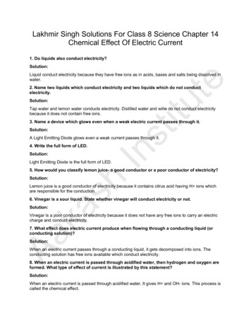
API 537 / ISO 25457 Flare Selection Graphic31
the practices set forth in ISO 23251 / API 521.! When API 537 was written, manufacturers’ and operating companies’ input was sought so the final document reflected prevailing technology expertise. API 521 Task Force members worked together with the API 537 members to write this Flare Details Standard. !