Transcription
I N T RO D U C T I O N TOHOT ISOSTATICPRESSINGTECHNOLOGYA guide for Designers and EngineersBenefits The HIP Process DesignTechnical Guidelines Case Studieswww.epma.com/hipAN EPMA SECTORAL GROUPPromoting Powder Metallurgy Technologyeuropean powdermetallurgy association
European Hot Isostatic Pressing GroupWhat is the European Hot Isostatic Pressing Group?The European HIP Group (EuroHIP) was formed in November 2009 represents the entire HIP sector supplychain from end users, through to component makers and raw materials suppliers. The main objectives are: To increase the awareness of the PM HIP technology, with a special (but not exclusive) focus on semifinished, Near Net Shape, as-HIPed and compound PM products To enable the benefits of joint action; for example through research programmes, benchmarking andexchange of statistics To improve the understanding of the benefits of PM HIP technology by end users, designers, mechanicalengineers, metallurgists and students To assist in the development of International Standards for the PM HIP SectorBy joining the EuroHIP group, a company gains access to the leading PM HIP network inEurope, from the full range of EPMA activities in areas such as REACH legislation, SummerSchools and publications, to name but a few.You will need to be an EPMA member to gain full access to the all of the groups benefitsincluding invitation only meetings.More information about EuroHIP can be found at www.epma.com/hip Sandvik PowdermetRepresenting the European PM industryeuropean powdermetallurgy associationEPMA Membership Benefits10 Reasons to join the EPMA1Enhance your market knowledge through access tounique industry information using our range of powdermetal PM statistics, presentations and papers.6Keep updated on industry news and developments throughthe Email News service, journal ‘Powder Metallurgy’ andthe EPMA newsletter – all free to EPMA Members*.2Improve your product development through access toEU and EPMA Member initiated R&D programmes.7Develop your high-level networking opportunitiesthrough EPMA Sectoral Groups, training seminars andthe general assembly.3Save money by receiving substantial discounts onattending and exhibiting at the leading annual Euro PMCongress and Exhibition and our series of training courses.8Keep compliant with ISO 9001:2000 and ISO/TS16949:2002 by participanting in the EPMA Europe-WideBenchmarking programme.4Obtain unique international access to government via ourlobbying of the EU on key issues such as REACH, ISOstandards and health and safety legislation.9Access Member only content from a range of sources viathe EPMA website Members Area.5Promote your sales through free advertising via an entryin the EPMA Members Directory on one of the world’smost visited PM websites.10Develop the market for your products by supportingpromotion of PM technology via exhibitions and webbased information.Join EPMA at www.epma.com/membership
HIP - Hot Isostatic PressingCONTENTSHot Isostatic Pressing (HIP)HIP has established itself in the past decade as a competitive and proven manufacturing process for the productionof complex and highly specified components made from a wide range of metals and/or ceramics.These components are currently being used in a number of industry sectors that have highly demandingenvironments for example: aerospace, offshore, energy and medical. In this guide, which is aimed at users or potentialusers of HIPped parts, we will focus on the use of metal powders as the raw material used in the process and howthey can deliver your requirements.Page1. INTRODUCTION 3Promoting Powder Metallurgy Technology2. BENEFITS OF HIP TECHNOLOGY AND ITS MAIN USES2.1 - The Main Benefits of the PM HIP technology2.2 - PM HIP Uses and Applications2.3 - Comparison with Other Manufacturing Technologies44563. THE PM HIP PROCESS 73.1 - Powder Manufacturing8-93.2 - Container Manufacturing103.3 - Container Filling and Outgassing103.4 - The Hot Isostatic Pressing Process11 - 123.5 - Container Removal133.6 - Post Processing Operations133.7 - Quality and Testing134. MICROSTRUCTURE OF PM HIP PARTS4.1 - Stainless Steels4.2 - High Speed Tool Steels1414155. DESIGN GUIDELINES 165.1 - Introduction165.2 - Computer Modelling16 - 175.3 - Container Materials185.4 - Container Shrinkage195.5 - Positioning of Container Welded Seams19 - 205.6 - Container Deformation20 - 215.7 - Tolerances of PM HIP parts215.8 - Summary216. CASE STUDIES 22 - 283
HIP - Hot Isostatic PressingACKNOWLEDGEMENTSEPMA would like to thank the following companies for sponsoring this brochure:Promoting Powder Metallurgy TechnologyEPMA would also like to thank the following people and companies for supplying images that have been used throughout thisbrochure:AREVA NP Atomising Systems LtdAtomising Systems LtdAubert et DuvalBodycoteCarpenter Powder Products ABEPMA Leonardo ProjectErasteel SAKennametal HTMKobelco Metal PowderMetal Technology Company Ltd (MTC)Metso Minerals IncOlle GrinderQuintus Technology ABRolls RoyceSandvik Powdermet ABSyntertechSpecial Thanks to:Beat Hofer and Adeline Riou for their editorial input and to the EuroHIP group members for their support.Lionel Aboussouan, Executive Director, EPMACopyright European Powder Metallurgy Association 2011, 2nd Edition, reprint 2016, reprint 2017, update (web only) 2018,reprint 2018, reprint 20194
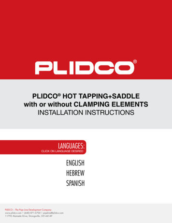
HIP - Hot Isostatic PressingINTRODUCTIONHIP - A high quality cost effective solution.Hot Isostatic Pressing (HIP) is a process to densify powders or cast and sintered parts in a furnace at high pressure(100-200 MPa) and at temperatures from 900 to 1250 C for example for steels and superalloys. The gas pressure actsuniformly in all directions to provide isostropic properties and 100% densification. It provides many benefits and hasbecome a viable and high performance alternative to conventional processes such as forging, casting and machining inmany applications.Its positioning is very complementary to other powder metallurgy (PM) processes such as Metal Injection Moulding(MIM), pressing and sintering, or the new additive manufacturing technologies. It is even used in combination with thesePM processes for part densification and the production of semi finished bars or slabs.As a result, HIP has developed over the years to become a high-performance, high-quality and cost-effective process forthe production of many metal (or ceramic) components.Positioning of PM HIP technology vs. other PM technologiesSource: Olle Grinder, Euro PM2009 Congress & ExhibitionNet Shape Nickel-base impeller for gas compressor(courtesy of Syntertech)Large nine tonne stainless Near Net Shape part for oiland gas industry (courtesy of Sandvik Powdermet)PM HSS gear cutting tool made from PM HIP bar(courtesy of Erasteel)Compound Injection Extruder(courtesy of Kennametal HTM)5Promoting Powder Metallurgy TechnologyA wide range of component types can be manufactured thanks to HIP. Its capabilities include large and massive near netshape metal components such as oil & gas parts weighing up to 30 tonnes, or net shape impellers up to one metre indiameter. Equally it can be used to make small PM HSS cutting tools, such as taps or drills made from PM HIPsemi-finished products, which can weigh less than 100 grams, or even very tiny parts such as dental brackets.
HIP - Hot Isostatic Pressing2. BENEFITS OF HIP TECHNOLOGY AND ITS MAIN USES2.1 The main benefits of the PM HIP technologyDesign FlexibilityNear-Net shapes, Net shapes or Bimetal constructionUse of composite materialsFreedom of part sizes and production seriesFreedom of alloysCost ReductionA lean manufacturing route, leading to shorter production leadtimesReduction of machining needsProducing single parts where previously several were requiredLess NDT needed and easier NDTReduced Environmental ImpactIn the case of near-net-shape and net-shape parts due to the excellent material yield compared with conventionalmetallurgyThanks to the above, PM HIP technology often proves a high quality and cost effective alternative to casting, forging and machining.800600400400MPaMPaPromoting Powder Metallurgy TechnologyPM HIP technology offers many benefits in the following key areas:Component quality and performanceDue to the fine and isotropic microstructures produced by HIPReduction of the number of welds on complex partsDense, without segregation20002000ForgingHIPUltimate Tensile Strength (RT)ForgingHIPMechanical Properties0.2 Proof StressFig 2.1: An example of comparative properties for various samples for 316L Steel achieved by forging &HIP (courtesy of Rolls Royce)6
HIP - Hot Isostatic Pressing2.2 PM HIP Uses and ApplicationsThis document focuses on HIP technology for the compaction of metal powders in a metal container. In this case, the powderis compacted through pressure while the temperature will ensure diffusion on the contact surface between powder grains,until all hollow spaces are closed so that a 100% density is achieved.However Hot Isostatic Pressing is also widely used for:The densification of cast partsThe densification of sintered powder parts such as cemented carbides or ceramicsThe densification of MIM partsDiffusion bonding between metal partsValve body for offshoresubsea stations(courtesy of Metso)Suction roll shell forpaper machines(courtesy of Metso)Bimetal injector nozzlefor diesel engines(courtesy of SandvikPowdermet)CERN end cover(courtesy of Metso)In each case HIP has established itself as the preferred process route in key applications.Before HIPAfter HIPFig 2.2: Closure of residual internal porosities by Hot Isostatic Pressing, through the combination of pressure and temperature7Promoting Powder Metallurgy TechnologyThanks to this wide range of uses HIP is currently employed for the manufacture of parts used in many industry sectors oftenin business critical and aggressive environments. Some examples of these include:EnergyProcess Industry and ToolingTransportation and AerospaceNuclear and ScientificOil and Gas
HIP - Hot Isostatic Pressing2.3 Comparison with other manufacturing technologiesPromoting Powder Metallurgy TechnologyPM HIP technology is often chosen as an alternative to conventional technologies such as forging and casting. In particular itcan offer the following features:Improved material properties, provided by the fine and homogenous isotropic microstructureImproved wear and corrosion resistance, through extended alloying possibilitiesReduction of the number of welds and associated cost and inspection issuesWith the near net shape option, two separate welded parts can be produced in one single stepThe bimetal option, using expensive materials only in functional areasReduction of machining costs, thanks to near net shape or net shape optionsNew solutions to produce complex internal cavities, which are difficult or impossible to machineThe benefit of PM HIP technology increases compared to cast or forged parts, especially when:Using high value materials such as alloyed steels or nickel- and cobalt-base alloys, because of the near net shape or netshape possibilitiesProducing small series of large and complex shapesWhere processing costs are high, due to a combination of multiple operations such as machining, welding and inspection.In summary HIP provides innovative solutions to shorten manufacturing cycle times and to produce small series of parts.WeldedForged*CastPM HIP**Microstructure in 3 dimensions (Isotropic rpoorgoodexcellentAbsence of segregationpoorgoodmediumexcellentStrength properties in 3 directions (Isotropic Strength)poorpoorgoodexcellentStrength properties levellowmediumlowhighNear final shapemediumlowexcellentmediumLarge series or repeated requestsmediumgoodexcellentmediumLost form (need of mould/container)nonoyesyesMaterial yieldhighlowhighhighModel necessarynonoyesnoPrice competitiveness - long seriesmediummediumhighmediumPrice competitiveness - short or single unit seriesmediumhighhighmediumDelivery time - long seriesmediumlowlowmediumDelivery time - short seriesmediumhighhighmediumTable 1: Comparison of different manufacturing technologies* Forging without die (ie neither open nor closed-die forging)** PM HIP Near Net Shape components. In the case of PM HIP Net Shape components, the shape precision and reproducibilityis excellent, like casting technology.8
HIP - Hot Isostatic Pressing3.THE PM HIP PROCESSThe production of a PM HIP component is leaner and shorter than usual conventional metallurgy processes. The cost of HIPrelative to energy and materials costs has decreased by 65% over the last two decades.Main process steps are:1. Powder manufacturing2. Container design and manufacturing3. Container filling with powder and sealing4. Hot Isostatic Pressing5. Container removal6. Post processing operationsThese are outlined in the schematic fig.3.1Net Shape PartBimetal PartMachined PM components(from bars or plates)Fig 3.1: PM Production RouteFig 3.3: Pouring melt into atomiser(courtesy of Atomising Systems)Fig 3.4: Loading container into HIPvessel (courtesy of Bodycote)Fig 3.5: Hot loading of HIP unit(courtesy of Kobelco)9Promoting Powder Metallurgy TechnologyNear NetShape Part
HIP - Hot Isostatic Pressing3.1 Powder ManufacturingThe most suitable metal powders for Hot Isostatic Pressing are produced by gas atomisation because of :The perfectly spherical powder shapeThe high fill density, thanks to the spherical shape and particle size distributionThe excellent reproducibility of particle size distribution, ensuring consistent and predictable deformation behaviorThe wide range of possible alloys, due to the rapid solidification rate.Promoting Powder Metallurgy TechnologyNote: gas atomisation is a physical method to obtain metal powders, like water atomization or centrifugal atomisation, asopposed to chemical or mechanical methods.Fig 3.6: SEM picture of gas atomized powders (courtesy of Erasteel)The gas atomisation process starts with molten metal pouring from a tundish through a nozzle. The stream of molten metal isthen hit by jets of inert gas such as nitrogen or argon and atomized into very small droplets, which cool down and solidify whenfalling inside the atomisation tower. Powders are then collected in a can.Molten metalInert gas jetsAtomised metal powderCollecting canFig 3.7: Sketch of the gas atomisation process10
HIP - Hot Isostatic PressingA wide range of metal powders can be hot isostatically pressed. In addition to standard or customized compositions of steels,nickel-base and cobalt-base alloys, many powders are compacted by hot isostatic pressing such as Titanium, Copper, Lead,Tin, Magnesium and Aluminium alloys. Another benefit of the PM HIP technology process is that new alloy compositionswhich are impossible to cast or forge can be considered thanks to the rapid solidification process. Indeed, during hot isostaticpressing, the elements do not have time to segregate like in cast parts, because the temperature is below the melting point( 0.8 x T solidus).This possibility has been very valuable for metallurgists to invent new alloy compositions for instance in the field of :Tool steels for higher wear or temperature resistanceStainless steels for high corrosion resistance in difficult environmentsComposite materials e.g. wear resistant metal and ceramic compositesStainless SteelsD2D7H13High Speed SteelsPM23PM30PM60A11M4T15Ni-Based AlloysNi 625Ni 690Ni 718AstroloyCo-Based AlloysCo 6Co 12Co FPromoting Powder Metallurgy Technology17-4 PH304L, 316L,410, 420, 4402205, 2507254 SMO 654 SMO Tool SteelsS31254Table 2: A few examples of standard powder alloys used for Hot Isostatic PressingFig 3.8: SEM picture of gas atomized powder(courtesy of Carpenter Powder Products AB)Fig 3.9: Gas atomized powders for Hot Isostatic Pressing(courtesy of Erasteel)11
HIP - Hot Isostatic Pressing3.2 Container manufacturingContainer manufacturing involves the following steps:1. Container sheet cutting and forming/shaping2. Assembly of steel sheets and optionally pipes and metallic inserts by TIG welding3. Leak testing, by evacuating the container and introducing helium or argon under pressure. If a leak is detected and located,repair is undertaken.Promoting Powder Metallurgy TechnologyThe integrity of welds is critical, otherwise when the vessel is pressurized, argon will enter the container and becomeentrapped in the powder mass. The argon will remain in the material and argon-filled pores will strongly deteriorate themechanical properties.Fig 3.10: Welding of a 2000 kg container (courtesy Bodycote)3.3 Container filling and outgassingOnce assured that the container is leak-free, the powder is introduced via a fill-tube. In order to achieve maximum anduniform packing of the powder, which is necessary to ensure a predictable and consistent shrinkage, a vibration table is used.Vibration will allow the powder to better fill narrow spaces and remote areas. In special cases such as critical aerospaceapplications, the filling operation is done under inert gas or vacuum to minimize contamination of the powder.The next step is outgassing to remove adsorbed gases and water vapor. After outgassing, the fill tube is welded to seal thecontainer. The absence of leaks is critical. Otherwise, when the HIP vessel is pressurized, argon will enter the container andbecome entrapped in the powder mass, creating argon-filled pores with damaging effects on the mechanical properties.Fig 3.11: Example of container construction with filling / evacuation tubes (courtesy of Rolls Royce.)12
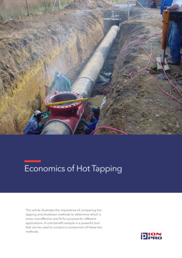
HIP - Hot Isostatic Pressing3.4 The Hot Isostatic Pressing ProcessDuring the hot isostatic pressing process, the temperature, argon-gas pressure and holding time will vary depending on thematerial types.After filling and closing, the HIP vessel is evacuated to eliminate the air. Then, while heating up, Argon gas pressure is increasedin the vessel. After reaching the calculated pressure, the increase in pressure is done through gas thermal expansion. In theholding time, gas pressure and temperature are constant. After this, a rapid cooling takes place, with decreasing pressure andtemperature.Chosen temperatures are below approx. 0.8 x T solidus, to avoid having a liquid phase.The gas used is generally Argon but in special applications, other gases or gas mixtures are used.The rise in pressure is built up with a compressorThe gas pressure is equal inside and outside the insulation. But the gas density is higher outside the insulation than insidebecause of the lower temperature.A HIP treatment cycle usually lasts from 8 hours up to 24 hours.HIP Cycle: Conventional Cooling versus URC1.Vacuum2. Equalization3. Pumping4. Heating5. Holding6. Cooling7. Equalization8. Backpumping9. ReleaseFig 3.12: Typical HIP cycle with and without uniform rapid cooling (URC) (courtesy of Avure Technologies)13Promoting Powder Metallurgy TechnologyModern HIP systems can feature uniform rapid cooling (URC) which circulates lower temperature gas to cool the part ata controlled rate of up to 100 C/min. The HIP quenching technique cuts cycle time dramatically by shortening the coolingstage by as much as 80%. It also provides the benefit of combining heat treatment with HIP in a single step. The uniform rapidcooling restricts grain growth and thermal distortion of the parts and avoids surface contamination by using high purity argongas.
HIP - Hot Isostatic PressingA HIP unit consists mainly of a pressure vessel, a heating system and an Argon gas system.Various HIP constructions are available:with or without a frame (For pressures above 100 MPa and HIP diameters above 900mm, frame construction is chosen forsafety reasonswith or without top screw thread locking systemswith different heating systemsMolybdenum furnaces are used for temperatures up to 1350 C and carbon graphite/tungsten furnaces up to 2200 C. Inside thepressure vessel, insulation (ceramic fibers and Molybdenum sheets) is used to protect the steel pressure vessel against the heatand to hold the high temperature inside the insulation. The bottom, cover and pressure vessel are water cooled to protect thesealing ring and the vessel against the heat.Promoting Powder Metallurgy TechnologyIn large HIP units, diameters can reach 2200mm and height of more than 4000mm, with a capacity of up to 30 tonnes.Gas InletTop owder ina containerHeaterSupportBottomClosureFig 3.13: Schematic of HIP furnaceFig 3.14: Lab Scale HIP unit, (courtesy of Kobelco)14Fig 3.15: Large-scale HIP unit (courtesy of MTC / Avure)
HIP - Hot Isostatic Pressing3.5 Container removalAfter HIP, the container can be removed (when the container is not to be re-used) by :MachiningAcid picklingSlipping nal accuracyTime consuming and costlyIf workable(tool accessibility)PicklingNo machining demandSpecial pickling bath withenvironmental protectionOnly for stainless parts withlow carbon steel containerSlip OffNo machining demandCost, for the layerGlass container orseparation layer necessaryPromoting Powder Metallurgy TechnologyMethodTable 3: Advantages and disadvantages of various options for container removal3.6 Post processing operationsAfter container removal, various additional operations can take place, including:Heat treatmentMachiningFinish grindingSurface treatmentAssembly3.7 Quality and TestingDepending on the size and value of the parts being made various types of quality testing will be undertaken. Two of the mostcommon are ultrasonic testing and dye penetrant inspection. CAT scanning is also used in critical high value applications.Fig 3.16: Diffusion bonded partsmanufactured via HIP process(courtesy of MTC)Fig 3.17: Injection extruder, compound(courtesy of Kennametal HTM)Fig 3.18: Manifold with 1-7 tonnessections assembled by welding(courtesy of Sandvik Powdermet AB)15
HIP - Hot Isostatic Pressing4. MICROSTRUCTURE OF PM HIP PARTSPromoting Powder Metallurgy TechnologyThanks to the rapid solidification process, fine and regular microstructures can be obtained thanks to the PM HIP technology,with strength values similar to those of forged parts.CastPM HIPForgedFig 4.1: Cast, forged and PM HIP microstructures of duplex stainless steel (courtesy of Metso)The two examples below highlight some of the key benefits provided by this fine and isotropic microstructure.4.1 Stainless SteelsWhen using HIP with stainless steels companies can obtain components with:An excellent combination of toughness and strengthIsotropic mechanical propertiesSame or better mechanical properties than forged productsSame or better corrosion resistance than forged productsStainless 2205PM HIPStainless 2205ForgedStainless 316LNPM HIPx100Stainless 316LNForgedFig 4.2: HIPped and forged microstructures for stainless steels(courtesy of Carpenter (2205) and Areva (316LN))16x100
HIP - Hot Isostatic Pressing4.2 High Speed Tool SteelsThe use of HIP with tool steels enables:Longer tool lifeMore reliable tool lifeBetter fatigue strengthBetter wear resistance due to higher carbide contentPromoting Powder Metallurgy TechnologyPM HIP HSSForged HSSFig 4.3: HIPped and forged microstructures for high speed steels (courtesy of Erasteel)17
HIP - Hot Isostatic Pressing5. DESIGN GUIDELINES5.1 IntroductionPromoting Powder Metallurgy TechnologyThese design guidelines provide some hints regarding PM HIP component design and manufacturing, so that potential users ofthe technology understand better the possibilities and issues specific to the PM HIP technology.Component designers can choose between four different options when considering the PM HIP technology:Simple shapes such as round, tubular or flat bar that will either be further machined or forged and rolledNear-net-shapes (NNS) which will reduce the need for machining or weldingComplex net-shapes (NS) which eliminate the need for machining in the functional parts of the component. This providesmore freedom in designing components and geometries impossible to machineBimetal or composite construction, where a metal powder layer will be HIPped for instance on a conventional metalsubstrate, as an alternative to PTA or spraying technologies. In this case, powders are only used in the functional area of thecomponent.Bimetal or composite partsSolid-powder or Powder-powderNear Net Shape (NNS)Reducing the need for machiningPump HousingValve BodySemi-Finished ProductsFor cost efficiency, further forged AND rolledComplex Net ShapeRequiring no further machiningFig 5.1: Possible options when designing PM HIP components5.2 Computer ModellingComputer modelling is used, in combination with the experience of HIP design engineers, to simulate accurately the powderdensification and shrinkage behavior and to achieve optimum container geometry and dimensions.Computer modelling allows optimization of the HIP process in particular for complex geometries. It also allows designersto get as close as possible to the finished shape, thereby eliminating expensive machining operations or avoiding any risk ofundersize part.Computer modelling is useful in particular in the case of sharp corners, when there are different container thicknesses or forcomplex net shape parts.18
HIP - Hot Isostatic PressingPromoting Powder Metallurgy TechnologyFEA predicted vs. HIP targetPost HIP vs. final machinedFig 5.2: Examples of HIP part modelling (Courtesy Bodycote)CAD image of machined and forged valve bodySimplified geometryof the part (HIP target)Can design based onHIP target geometryFinal shape predictionsusing FEA modelingFig 5.3: HIP component design steps (Courtesy Bodycote)19
HIP - Hot Isostatic Pressing5.3 Container materialsContainer materials and thickness are very important parameters when designing a PM HIP part.The container must satisfy the following considerations:It must be strong enough to maintain shape and dimensional control prior to and during HIP.It must be soft and malleable at HIP temperature.It must be compatible with the powder being processed and not penetrate nor react with the powder mass.It must be leak proof both at low and high pressures.It must be weldable for secure sealing and be removable after HIP.Promoting Powder Metallurgy TechnologyThe most common container materials are low carbon steels or stainless steels. However in specific cases, containers can bemade of high temperature material such as titanium or glass for the compaction of refractory materials. The normal containerthickness is between 2 and 3mm.Fig 5.4: Example of Near Net Shape container construction (courtesy of Kennametal HTM)Container MaterialCostDeformation 800 C 800 CStartingPressure *WeldabilityLow Carbon Steelexcellentmediumgood 100 bargoodStainless Steelmediumgoodgood 50 bargoodHigh Temperature Materialshighpoormedium 10 barlowGlassgoodpoorgood 10 barmediumHandlingRisk of cracks* To avoid cracks in the containerContainer MaterialContainer removalDecompositionAcidificationMachiningLow Carbon SteelgoodlowpoorgoodgoodStainless SteelgoodlowpoorpoorgoodHigh Temperature ntpoorpoorTable 4: Comparison of different container materials20
HIP - Hot Isostatic Pressing5.4 Container shrinkageDuring Hot Isostatic Pressing, the container shrinkage is not isotropic and depends on many parameters such as:Container materialContainer overall geometryContainer thicknessPositioning of container weldsVariations in powder fill density within the containerFor instance the end plates of a straight cylindrical container will not shrink radially to the same extent as will the cylindricalsection. This results in an end effect called « elephant’s foot » or « hourglass effect ».AfterHIPBeforePromoting Powder Metallurgy TechnologyBeforeAfterHIPFig 5.5: Effect of sheet thickness in HIP container design(F. Thümmler, Introduction to Powder Metallurgy, published by Institute of Materials, London, 1993)5.5 Positioning of container welded seamsThe positioning of welded seams on the container has a major impact on its deformation behavior during hot isostaticpressing. This must be taken into account when designing PM HIP part as shown in the table below which shows theadvantages and disadvantages of each method.Method 14 welded seamsin the cornersMethod 22 welded seamson the side wallsMethod 32 welded seams onthe side walls andno sharp cornersMethod 4Special constructionwith 4 welded seamsFig 5.6: Different container construction optionsRegular deformation and less welding work are the main benefits of method 3. In method 4, the construction reduces thestress on welded seams because the gas pressure is applied on both sides. Therefore, design methods 3 and 4 are usuallypreferred to methods 1 and 2.21
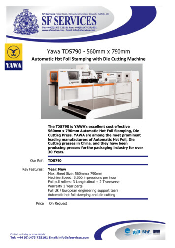
AdvantageDisadvantageDeformationMethod 1Simple constructionRisk of cracks. Too rigidcorners. A lot of welding work.Strong in the centreMethod 2Less welding workRisk of cracking in corners. Need toform sheets in U-shape.Strong in the centreMethod 3Regular deformation. Less weldingwork and lower risk of cracks.Need to form sheet in U-shape withradiusRegular shrinkageMethod 4Lower risks of cracksMore welding work. More rigid corner.Strong in the centreTable 5: Comparison of different welding seam positions5.6 Container DeformationAfter the HIP process, the container will become deformed. This deformation will also vary depending on chosenconstruction options and the type of contents as can be seen in Fig 5.7 below.powderpowder - solidhollow cyclinderCONTAINERBEFORE HIP5powder Bsolid4powdersolidsolid - solidpowder A - powder Bpowder A - powder Bpowderpowder - solid3solid2powder1solid - solidpowder Apowderhollow cyclinderpowder Apowder BsolidpowdersolidsolidDEFORMATIONAFTER HIPpowderPromoting Powder Metallurgy TechnologyHIP - Hot Isostatic PressingFig 5.7: Container deformation after HIP depending on chosen construction opt
Promoting Powder Metallurgy Technology INTRODUCTION HIP - A high quality cost effective solution. Hot Isostatic Pressing (HIP) is a process to densify powders or cast and sintered parts in a furnace at high pressure (100-200 MPa) and at temperatures from 900 to 1250 C for