Transcription
Trouble Shooting an Astron Linear Power SupplyJim Ussailis – W1EQOWe will need some tools: Philips screwdriver, VOM, and a load. NOT YOUR TRANSCEIVER!! Two loads capable of fullrated current and something at 1/4 current might be helpful. You will find that an analog VOM as well as a digital VOM thathas a transistor check section and a continuity beeper are both worthwhile. First a list of common problems and repairs is inorder:A.Quick Check for Common Failures and Possible RemediesSymptomNo outputReceiver hums, Reports of transmitted humAcrid smell, possibly hissLow output voltageLow output currentB.Possible RemedyRead Sections B & CCheck C5 & C1, replaceCheck electrolytic, Look for leaks of electrolyteTransformer, R6, R7, pot R5 on PCB, LM723Pass transistor(s), LM723No OutputFirst, do the obvious: Unplug the supply1, connect a load that runs the supply around half of its rated current, change the fuse &plug in the supply. Measure voltage at the output terminals. Does the supply work? No? Continue.CAUTION ALWAYS UNPLUG THE SUPPLY BEFORE YOU MAKE ANY CHANGE B.1Replacement Fuse OK.Assuming the fuse didn’t blow when you plugged the supply in, I suggest you remove the supply cover and measure the DCvoltage at those screws that attach the PCB to a big, fat, capacitor that is also mounted to the chassis. Do this both with andwithout a load on the supply output. You should get something around 18 to 24 volts DC, with the higher voltage for a light orno load.If the voltage is reasonably correct, the transformer, and rectifier are OK. We need to look elsewhere. As a minimum the repairwill use inexpensive components as we just tested “Big Bucks,” (transformer).B.2Replacement Fuse Blew.If the fuse blew, then we need to determine which block is the problem. First, however we should disconnect the AC line spikeprotector / varistor as it could have shorted because of induced lightning on the AC mains.This device is a black, ceramic disc capacitor shaped, gadgets soldered directly on the input side of the power transformer.Unplug the supply & unsolder one side of the varistor from the transformer, measure the device with an ohmmeter. It shouldread a high resistance to an ohmmeter and never show a short circuit. In any event, check the supply with the varistor still outof the circuit. If the supply works now, replace the varistor.I’ve read that some Astron supplies have a ceramic disc capacitor between the AC mains power wire (Black) 2 and ground.Remove and check this capacitor for a short. My supplies do not have this capacitor.I’ve also read that a failure point can be the crimp connectors and attachments to the case and supply output terminals. Youmight check these while you are there.B. 3Isolate High Current Rectifier and Transformer.Remove the red wire going from the bridge rectifier (which is used only as a full-wave rectifier) to the PCB board. It might behelpful to remove the screw from the filter capacitor that retains the PCB. This wire can be removed either from the PCB or therectifier itself.Replace the blown fuse and turn on the supply. If the fuse again blows, remove the two wires going from the transformer to therectifier, AND remove the two white wires going from the transformer to the PCB. Again, power up the supply. If the fuseblows the transformer has a shorted turn. You might check the switch before you use the transformer for antenna wire.B. 4The Fuse Did Not Blow.The transformer is probably OK. Check the diodes in the bridge rectifier block. One or both could be shorted. Only two areused of the four in the bridge diode pack, but I would check the other two also. If there is a short, replace the rectifier assembly,reconnect wires, and retest.YCCC ScuttlebuttAugust 2015Page3
Check the filter capacitor (large cylindrical object that holds PCB). Using the analog VOM in a resistance mode, place the redplus lead on capacitor and black minus lead on capacitor - terminals. The capacitor will slowly charge, resulting in aclimbing resistance. This may take a minute or two. If it does not charge, or quickly shows a high reading, replace it.A non-charge indicates a short; quickly charging indicates a failed (open) capacitor which will cause AC ripple on the supplyoutput and hum on your transmitted signal. If there is a short, disconnect the screws holding the PCB, lift the PCB from thecapacitor, recheck the supply with only a DC voltmeter (no load) at the supply output. If there is a 13.8 volt reading, thecapacitor is the problem. Replace it.There are two other relatively easy to check components that will cause no output and probably not blow the fuse: There aretwo capacitors on the supply output leads, C131 (electrolytic) and C 103 (tiny ceramic across C131) Check them for a short.Again C131 will show some charging effect. One of the mica insulators under one of the pass transistors could also have failed.Check each collector (the case) to ground for continuity. The resistance should be high. I measured greater than 400 K ohmsfor my RS-20A supply.B. 5Dedicated LM723 Power Supply.The large filter capacitor is not the only filter capacitor in the Astron circuit. They have a separate power supply for theLM723C chip, with its own filter capacitor, C1, rectifier diodes, D1 and D2, and a transient voltage suppression diode, (CR6,PK6E39A)3. electrically across the circuit.Check LM723C supply at D1 or D2 cathode on the trace side of the PCB for 25 to 29 Volts (load dependant) output. If OK,skip to Section C.1, below.If there is no or limited output, first check across the two white wires attached to anode sides of D1 and D2 for about 43 VoltsAC. If this voltage is much lower, there may be a problem in the transformer. First, however, continue to check the DC side ofthis supply.Unplug the supply and check, on PCB component side, CR6, D1, and D2 using diode checker function of your VOM. Checkcapacitor C1 with an ohmmeter. The diodes should conduct in one direction and not indicate a short, the capacitor should showa fairly fast charging rate and also not show a short.If the diodes and capacitor are all OK, then I would remove the white wires and carefully measure the transformer voltageagain. If it is still low, there is an issue with the transformer.If all the above is OK, then the no output and potential fuse blowing problems are probably a failure in either: crowbar circuit,current limit circuit, voltage adjustment circuit or pass transistors. Let’s do the easier tests first.CCheck Pass Transistors.A pass transistor failure is the reason the crowbar circuit exists. If the failure is due to a shorted pass transistor, than the dioderectifier peak voltage will appear at the supply output. While the transmitter section of your transceiver may draw enoughcurrent to lower the supply output voltage to a reasonable value, chances are very good the receiver section will not. Forexample, you are running low power in a RTTY contest, you go from transmit to receive and, a poof, you are out of thecontest. This is not good.So for this no output condition, thank Astron for adding the crowbar network. First let’s check the pass transistors.An Astron supply can have from one to many paralleled pass transistors. More current draw requires more of them. Becausethe current gain of these transistors can vary from lot-to-lot, a low value, series, current balancing resistor is added to eachemitter output. Typically, 0.1 ohm, 5%, five or 10 Watt, wire wound.The first step is to disconnect any load that may be at the supply output. Leave the regulator PCB disconnected from theelectrolytic, then measure the value of each current balancing resistor. They should be within 5% of the stated value.Next let’s check the transistors. Place your VOM in diode checking mode. Attach the negative probe to the base of any passtransistor.It is easy to Identify pass transistor connections. The pass transistors are connected in parallel, except for the emitters: Thecollectors are tied with a piece of bare bus wire soldered near one of the screw terminals of each transistor. The collectors arealso internally tied to the transistor case. A piece of heavy red wire extends from one of the collector terminals to the PCB.This wire may be attached to a center terminal and bar on the socket. This bar also forms the nuts for the screws.The bases are connected together with a section of light duty, covered, wire. Another light duty wire extends from one baseconnection to the PCB. Each emitter is connected to a low value power resistor. The other ends of the power resistors are tiedtogether.YCCC ScuttlebuttAugust 2015Page4
Connect a VOM positive lead to any emitter, record the reading. Then swap the VOM leads and record the reading. Finallytake the same readings with the leads connected between the base and collector. On my supply the collector is also electricallyattached to a terminal between the base and emitter pins.You may find the base to emitter readings strange. This is because there is about 6K ohms from the base to negative andground. You should also to take readings with an analog VOM.I measured the values below for my operational RS-20A supply.Diode checker VOMBase toConnectionsEmitterBlack (-) lead to baseRed lead ( ) to baseBase toCollectorConnections0.467infiniteBlack lead (-) to baseRed lead ( ) to base0.4700.67Analog VOMBase toEmitter 150 OhmsCharging to 6KBase toCollector 150 OhmsinfiniteCheck that no readings are zero ohms as this indicates a shorted transistor. If there is a short, remove each transistor and checkthem individually. Replace any shorted transistors.ALWAYS unplug the supply before each measurement or PCB removal. Remember the fuse holder is LIVE.DCheck Voltage Adjustment Resistors.The voltage adjustment circuit (on component side of PCB) can cause the crowbar circuit to turn on preventing a supply outputand a potential blown fuse issue. That circuit is run but R6, R7, adjustment R5 and the LM723. Should R6 fail open, the supplyoutput goes above 18 volts, the crowbar fires and the output goes to zero4. A good quick check is for R6 at 2.2K ohms, or less.Check R5 and R7 also. An additional shunt resistor is shown in the schematic across R6. Perhaps this is an afterthought toaccommodate a different adjustment potentiometer. My supplies do not have this resistor.ECheck Crowbar Circuit.E. 1Check SCR.The easiest method is to temporally disconnect the crowbarcircuit. First REMOVE any equipment you may have attached tothe supply. Next discharge the smoothing capacitor(s) with a cliplead. Remove the PCB by removing the two screws that hold thePCB to the DC smoothing capacitor.ConnectionPlus lead to plus outputMinus lead to minus outputMinus lead to plus outputPlus lead to minus outputMeasurement300 Ohms, steadyClimbs to 3 K ohmsNext place a clip lead across the output supply terminals for aminute or so to discharge any other capacitors. Then take an analog VOM and measure resistance across these terminals.Compare the results with the table below. If there is a short circuit, look for frayed wires or some other obvious problem. Ifnothing amiss is found, change the SCR.E. 2Check Turn-on Signal to SCR.Locate PCB connection 1 on the underside of the PCB. Unsolder the wire connected there. (Black on my RS-20A) Thisremoves the turn-on signal to the SCR. Again, turn on the supply and measure the voltage at the output. If the voltage iscorrect, the problem is in the crowbar firing circuit, Q1, CR1, C6 and associated resistors.On a smaller supply (RS-12A) there is no connection at connection 1. If that is your case, locate R11 and R12 on the lower sideof the PCB. Note that these resistors are attached together through a short trace. Carefully remove the two near ends of theseresistors, lift them a small amount above the component side of the PCB and attach them together with a tiny amount of solder,while keeping this connection from touching anything else. This also removes the turn-on signal from the SCR. Follow theparagraph above.E.3Test Crowbar Circuit For Proper Operation.Attach a clip lead to a pass transistor emitter / balance resistor lead. Attach another clip lead to a pass transistor collectorattachment screw. Keep these leads separated. Attach an analog VOM set to read 20 volts at the supply output terminals. Becareful not to let the VOM leads touch the heat sink.Plug in and turn on the supply. Verify an approximate output voltage, then touch the unused ends of the clip leads to eachother. There should be a spark, the voltmeter might rise for a second, but will read about zero and stay there. Disconnect theclip leads. The voltmeter will not return to any appreciable voltage. The supply power must be recycled for a normal outputvoltage to appear. This is how the crowbar function operates.YCCC ScuttlebuttAugust 2015Page5
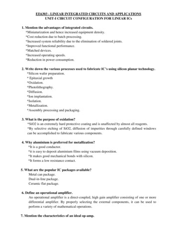
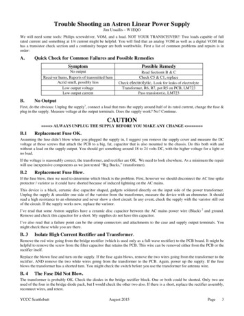
FCheck Current Limit Circuit.As I have read, the current limit foldback circuit works when the output current exceeds 70 amps. I’ve tried a short across theoutput that only succeeded in blowing the AC line fuse. It appears that neither of my Astron supplies can approach this currentlimit.So the only suggestion is to compare the voltages at pins 2 (current limit), 3 (current sense), and 4, (inverting input) with thosein below. Also, check the resistance values of R3, R4, and Rx;. Finally check diode CR3 (1N4148) using the VOM diodechecker.GCheck For Shorts on PCB.Annotated voltage measurement pictures of both PCBs are attached below. I purposely left the PCB in the condition that Ifound. In several instances I also over annotated, not because I felt the reader couldn’t follow the diagram, but because I had adifficult time finding small inter-land traces or open space between lands due to unwashed rosin flux.LM723C Regulator Voltages - RS-20A Power Supply - No loadVoltage0.07.14mV7.13mV7.14mV13.32mV13.14mV120 mVPinFunction7V6Vref5 Input4- Input3Current sense2Current limit1NCTransformerBlue wire 17.89 VacYellow wire 17.90VacFunctionNCVzVoutVcV Freq CompNCPin891011121314Voltage25 mV8.1614.3529.329.616.2213.2Pass TransistorsE 13.83 VoltsB 14.36 VoltsC 23.90 VoltsMeasurements taken with a Radio Shack, Micronta, 22-184 digital VOM.Negative lead attached to power supply negative output post. - 7 Aug 2015Except for the 43 V AC measurements between the diodes D1 and D2, all measurements are with respect to the negativesupply output lead.HLow Voltage.So far we have dealt with catastrophic failure; a short circuit, blown transistor, etc. Now we shall cover low voltage and lowcurrent failures. One helpful piece of equipment is an almost full current load for your supply. This large low values resistors,often found at a flea marketFirst calculate what resistance will be required to load your supply to draw about 50 to 80% of its full current at 13.8 volts.Let’s assume you are repairing a 35 amp supply, so you need a load that draws 20 amps:R E / I 13.8 / 20 0.69 Ohms 0.7 Ohms.P E * I 13.8 * 20 270 Watts.Any wattage above 100 or so will work as we will take very quick measurements. A small fan will also help cooling the load.This resistor can also be constructed from any series / parallel combination of smaller value (easier to obtain) resistors. Don’toverlook that bag of 27 Ohm, 5 Watt resistors for almost free.The low voltage issue can be caused by almost any failure in the supply circuit. First we will concentrate on the easier to testsections.H.1Check Transformer & Rectifier Diodes.This test is easily done by attaching a VOM lead to the negative output post and the positive lead to one the collectors of thepass transistors. The case top doesn’t have to be removed. Adjust the VOM to read a 20 or 25 volt scale. With no load attached,turn on the supply and note the voltage. It should be about 23 Volts. Then load the supply so that 50 to 70% of its rated currentis drawn. The voltage should fall, but be remain above 19 Volts or so.If the voltage has fallen below about 17 there is either a problem with the transformer, or the diode bridge. There is a slightchance of an unusual failure in the large filter (smoothing) capacitor.Shut the supply off, open & remove the case cover, remove the screws that hold the PCB to the capacitor and place a piece ofinsulating material between the PCB and capacitor. Repeat the previous measurement with the capacitor out of the circuit.YCCC ScuttlebuttAugust 2015Page6
Next let’s isolate the rectifier bridge. Remove the two transformer wires that are attached to the bridge. Attach the VOM, setfor an AC voltage, between the negative supply post and one of the secondary transformer wires that connected to the diodebridge. You should read about 17.5 Volts5. Take the same measurement on the other wire you removed from the bridge. Theyshould be closely the same.Next electrically place your load across the VOM terminals and repeat the above measurements. They will fall a volt or two,and should be about the same. If one or both voltages are much lower with the load, the transformer probably has a “shortedturn” in one of its windings.If these voltages are OK, check the diode rectifier bridge with the diode checker position of your ohm-meter. If there is aproblem, change the diode bridge. If the transformer, rectifier, capacitor and pass transistors are all OK, then the problem is inthe PCB.H. 2Check PCB Voltages.Reassemble the transformer connections to the diode bridge, reconnect the PCB to the capacitor, and attach the load to theoutput terminals. We will be measuring PCB voltages. Review C.5, above.A list of voltages and two annotated pictures are attached below. Next, turn on the supply and measure the AC voltage6between PCB connections five and six. These two connections are on the upper right-hand edge of the PCB. Two whitetransformer wires lead to these terminals on the component side of the PCB. You should read about 43 Volts AC. This is theonly AC voltage present on the PCB.Next connect the negative lead of the VOM to the power supply negative terminal7. Check the voltage at the cathode of D1 andD2, the large foil area below the 43 Volt AC measurement. This should be about 29 Volts DC. This voltage runs the LM732Cchip. Potential failures are C1, D1, D2, CR6 (a transient absorber) and the LM723C.If it is OK, then measure the voltage on pin 4 of the LM723. The bottom arrangement for pins 7 and 14 is given on the PCBpicture for the RS-20A supply. Pin eight is marked as a figure in the copper just above pin eight on the right-hand side of thechip layout. The reading on Pin 4 should be close to 7.14 Volts. This value comes from the voltage adjustment potentiometer(R5) and a voltage divider (R6, R7), and determines the power supply output voltage.If neither of these measurements solve the low voltage problem, then check all the voltages given in the pictures. Since bothPCBs are very similar, I would use check my supply against both pictures. Also, use the VOM diode checker to check thetransistors and diodes on the PCB.YCCC ScuttlebuttAugust 2015Page7
Should there still be a problem, the only component left to replace the LM723C. I suggest you replace it with an LM723 (no‘C’), as the ‘C’ designation indicates a commercial version, rated for 0 to 70 C, while the non-‘C’ version that is rated for -55to 125 C.The LM723H is a ‘723 in a 10 lead metal can pack; the LM723E is a 20 lead surface mount pack. Both of these are unworkablein an Astron supply without a major PCB revision.JSupply Does Not Provide Rated Current.Review the section above. Generally when the current draw is insufficient, the voltage output falls off also, usually for thesame failure reasons. Look at the AC to DC block first. Check the transformer, rectifier and pass transistors.Then look at the PCB. Check voltages around the current limit circuitry. Pin 2 and Pin 3 of the LM723. I find the schematicfrom pg 11 of the National Semiconductor datasheet helpful, BUT do notice that the pin numbers there are for the LM723H, adifferent package. Don’t overlook the possibility of a shorted, small value, capacitor. If all fails, change the LM723C.KHum.You have reports of hum on your transmitted signal, but hear nothing in when receiving. This is a classic problem. Anincreased load on a supply with an “aging” filter capacitor cause increased the ripple voltage. The reason is that the designer ofthe supply set the regulation voltage low enough to do some of the ripple filtering. Unfortunately as the current draw increases,the voltage into the capacitor and regulator drops to the point now where the ripple that was “on top” of the DC voltage goesbelow the regulation voltage and onto the supply output. Hummmm.If you have an oscilloscope, you can easily see the ripple. Use an AC input, sync on “line.”Solution: Replace filter (smoothing) capacitor. Do not buy a new-old-stock (NOS) unit. Electrolytic capacitors often age whilejust sitting there. Do spend the extra to buy a new capacitor from a reputable supplier. This is not a flea market item.Notes:1 - Some web sites mention that the fuse holder might be improperly wired. They say the AC line should connect to the end pin, the ring isconnected to the wire going into the supply. This is done so that if you should remove a good fuse it’s exposed terminal and cover isn’t live.2 - In the electrical world, a black wire indicates the HOT side, a white wire is used for neutral and green for ground.3 - Presently manufactured by Littlefuse, available at Digikey4 - I tried this on my RS-12A. The crowbar circuit fired as expected.5 - I measured 17.39 on an RS-12A; 17.90 on an RS-20A6 - This AC voltage measurement is the only measurement between two terminals. All others are taken with respect to the negative powersupply lead.7 - I have read where some Astron supplies do not have case ground tied to the negative output.-. - - / - . - . / - . - . / - . - .YCCC ScuttlebuttAugust 2015Page8
YCCC ScuttlebuttAugust 2015Page9
They have a separate power supply for the LM723C chip, with its own filter capacitor, C1, rectifier diodes, D1 and D2, and a transient voltage suppression diode, (CR6, PK6E39A)3. electrically across the circuit. Check LM723C supply at D1 or D2 cathode on the trace side of t