Transcription
Kinematics, Kinetics,Amputee Gait (part 2)MCE 493/593 & ECE 492/592Prosthesis Design and ControlOctober 21, 2014Antonie J. (Ton) van den BogertMechanical EngineeringCleveland State University1
Homework due October 28 Download the data file and Matlab code for the 2Dkinematic/kinetic analysis (links in PDF)– Run the invdyn2d program Use the data to design impedance controllers for hip,knee and ankle– Optimization or trial and error– One control law for entire gait cycle– Show plots of actual joint moment and "best" controller Do this also for the hip joint– Will require additional code in invdyn2d.m
Today Additional notes on Vanderbilt leg Design of a passive exoskeleton– based on inverse dynamic data Studies of amputee gait
More than 4 phases would give better fit.So why not?impedance control(Sup, Int J Rob Res 2008).utilizes an impedance-based approach to generate joint torques. Such anapproach [.] generates stable and predictable behavior. The essence of theapproach is to characterize the knee and ankle behavior with a series of finite states[.] switching between appropriate equilibrium positions (of the virtual springs) ineach finite state. In this manner, the prosthesis is guaranteed to be passive withineach gait mode, and thus generates power simply by switching between modes. Asthe user initiates mode switching, the result is a predictable controller that, barringinput from the user, will always default to passive behavior.
Some concerns Bandwidth of (Winter) gait data is 6 Hz, so maybewe have 12 independent samples in the gait cycle. 16 parameters is already too many to identify from12 equations Passive does not imply stable– it's not really passive when frequently switching– slider crank model shows that leg will buckle when kneestiffness is less than 7 Nm/deg– fit to Winter data had k1 3.78 Nm/deg– what to do?
Inverse dynamics is not feedbackcontrol!Equation of motion:L sin θmL2θ mgL sin θ MSmall-angle approximation:mL2θ mgLθ MmgDesired movement:θθ A sin ωtInverse dynamics:MM mL2θ mgLθ mAL( g Lω 2 ) sin ωtInverted Pendulum mL( g Lω 2 )θ
ControllerFrom inverse dynamics: M kθk mL( g Lω 2 )Linear system dynamics with control:mL2θ mgLθ M mgLθ mL( g Lω 2 )θ mL2ω 2θ errors / perturbationsSolution:θ A sin ωt effect of errors / perturbations
A controller that might work:M kθ K p (θ A sin ωt ) K d (θ Aω cos ωt )inverse dynamicsposition feedbackvelocity feedbackNow, the controller also needs to know thedesired trajectory (A sin wt), and it needs to knowwhat time it is (t).This is not ideal either!
Moment-angle relationship duringmovement "pseudo-stiffness"When system is observed on its nominal trajectory:M mAL( g Lω ) sin ωtθ A sin ωt2Moment-angle diagram:slope mL( g Lω 2 )MθNo information about joint stiffness or feedback control!System needs to be perturbed to identify the feedback gains
Ankle pseudo-stiffnessAt normal speed: k 450 Nm/rad 8 Nm / degProsthetic feet are designed based on thisIs system still stable when k is too low?A.H. Hansen et al., J Biomech 2004
Exoskeleton designRewalk2003: Berkeleylower extremityexoskeleton (BLEEX)hydraulic, poweredby internalcombustion engineEkso BionicsParkerIndego
Military applications Running speed, backpack Estimated steady state power:600 W Peak power 2 kWJansen et al., ORNL Technical Report TM-2000/256
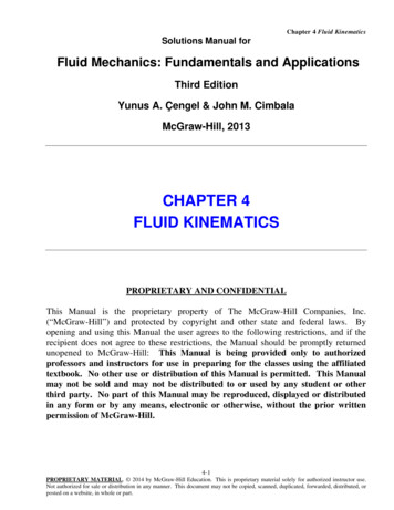
How does nature do it?Muscles span more than one joint! GastrocnemiusLong ial DigitalFlexorLong tendons & short muscle Deep DigitalFlexorCheck LigamentSuspensoryLigamentTransfer of energy: when joint requiresnegative power, power can betransferred to a joint where positivepower is needed. Storage of energy: when joint requiresnegative power, elastic energy can bestored until a time when positive poweris needed.Force generation: passive elasticity cancontribute to force production withoutenergy cost.
Theoretical "exotendon" designsABCDPulley mechanisms were optimized for maximal contribution tothe joint moments or joint powers required for walking
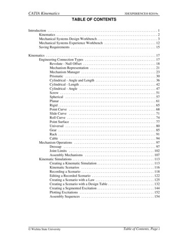
Kinematic/kinetic dataJoint Moments (right leg)60AnkleKnee40Joint Angles (right 0Knee40-80HipTime (% gait cycle)20required joint torques969084727866604854423624301861200Joint Power (right leg)-20200.00AnkleKnee150.00-40Hipjoint movements9688807264564840320.000Time (% gait cycle)50.0024-80100.0016-608Power (W)Angle (deg)00Moment (N m)Hip20-50.00-100.00Time (% gait cycle)required joint powersB. Stansfield et al., Gait & Posture 17: 81-87, 2003
Optimization of designjoint rotationsexotendonpulley systemdesign parametersexotendon forcesrequired joint momentsexotendon joint momentsrequired joint powersexotendon joint powershuman movementdatadesign evaluationresidual momentsresidual powersminimize
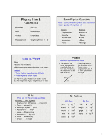
Results: single-joint design optimized for momentrightleftexotendon forcesjoint moments(right side)residual anklemomentA
Results: three-joint design optimized for momentexotendon forcesBjoint momentsresidualmoments
Results: double six-joint design optimized for momentexotendon forcesDjoint momentsresidualmoments
Results: summary of all design optimizations70% reduction in joint moment andjoint power is possible with apassive elastic cable-pulley systemwww.cadencebiomedical.comvan den Bogert, Biomed Eng Online, 2003
Results: spiral pulleys 26 design parameters optimized with simulatedannealing 50·109 designs evaluated mean residual moment is only10.15% of original momentresidual moments
Inverse dynamics is not control! Remember, the elastic system does not replace all of therequired moments– remainder can be used to provide control This would work for certain applications– military– patients who still have some muscular control (stroke, MS, incompletespinal cord injury) elastic forces assist and guide the movement– paralyzed patients, if there are additional motors that provide control motors can be half the size Electric motors might replicate these multi-DOF elastic forcefields, and do the energy storage/transfer
Video (Vanderbilt leg test subject)https://www.youtube.com/watch?v tj1Y5eEU-j4
Evaluation in amputee Sup et al., Self-Contained Powered Knee and Ankle Prosthesis:Initial Evaluation on a Transfemoral Amputee. IEEE Int ConfRehabil Robot. 2009 June 23; 2009: 638–644.doi:10.1109/ICORR.2009.5209625kknee 4.5 Nm/deg
Gait analysis resultsThis is not a clinical trial. Why not?
Amputee gait studies No studies on the Vanderbilt leg yet(clinicaltrials.gov) Below knee– Sanderson & Martin, Gait & Posture 1997 flex-foot, compared to other leg and to able-bodied Above knee– Johansson et al., Am J Phys Med Rehabil 2005 Mauch, Rheo, C-leg compared to each other– Segal et al., J Rehab Res Devel 2006 Mauch, C-Leg compared to other leg and able-bodied
Sanderson & Martin 1997 Methodswww.ossur.com6 able-bodied, 6 unilateral below knee amputeesamputees used the flex-foot1.2 m/s and 1.6 m/s, three trials at each speedAMTI force plate sampled at 240 HzSingle-camera (2D) video at 60 Hzdouble 2nd order Butterworth filter (5 Hz for foot markers,4 Hz knee, 3 Hz hip)– conventional 2D kinematics and inverse dynamics––––––
1.2 m/sankleangle & momentkneeangle & momenthipangle & moment
Johansson et al., 2005 8 unilateral AK amputees 4 C-leg users, 1 Mauch, 1 endolite, 1 Rheo, 1 4-bar all were tested with Mauch, C-leg, Rheo in random order– 10 hours of getting used to new prosthesis– Allurion foot used during all tests Vicon 3D mocap, AMTI force plate Bodybuilder software for kinematics/kinetics (3D?)
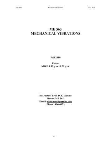
Prosthetic side
Segal et al., 2006 8 above-knee amputees, Mauch users 9 able-bodied controls amputees were tested with C-Leg and Mauch knee 10 Vicon cameras, 120 Hz; Kistler force plate 600 Hz Vicon Plug-in Gait software for 3D kinematics/kinetics
Prosthetic sideC-LegMauch SNSAble bodied control
Intact sideC-LegMauch SNSAble bodied control
What did I learn from the gait studies? All prosthetic knees show– almost no knee flexion in stance– no knee extension moment in stance– (except for the Vanderbilt test subject) Below-knee amputees also did this!– So maybe it's caused by the foot C-Leg and Rheo knee perform similar to Mauch knee– Is extra cost justified?– Normal gait tests may not reveal certain benefits (active stumblerecovery)
Oct 21, 2014 · Kinematics, Kinetics, Amputee Gait (part 2) MCE 493/593 & ECE 492/592 Prosthesis Design and