Transcription
Poulos, H. G. (2001). GeÂotechnique 51, No. 2, 95 113Piled raft foundations: design and applicationsH. G. POULOS Dans les situations ouÁ les fondations aÁ radier ne suf sent pasaÁ elles seules pour remplir les criteÁres de construction, il estpossible d'ameÂliorer les performances du radier en ajoutantdes piles. En utilisant un nombre limite de piles placeÂes aÁdes endroits strateÂgiques, on peut ameÂliorer la capaciteÂporteuse ultime et le tassement ainsi que la performance detassement diffeÂrentiel du radier. Cet expose se penche surl'utilisation de piles pour reÂduire le tassement et eÂtudie lesconditions dans lesquelles cette meÂthode peut reÂussir. NousdeÂcrivons certaines des caracteÂristiques du comportementd'un radier aÁ piles. Le processus de conception pour unradier aÁ pile peut eÃtre consideÂre comme comportant troiseÂtapes. La premieÁre est une eÂtape preÂliminaire pendantlaquelle les effets du nombre de piles sur la capaciteÂporteuse et le tassement sont eÂvalueÂs au moyen d'une analyse approximative. La seconde eÂtape consiste en un examenplus deÂtaille visant aÁ eÂvaluer l'endroit ouÁ les piles serontneÂcessaires et aÁ obtenir une indication sur les criteÁresneÂcessaires. La troisieÁme est une phase de conception deÂtailleÂe au cours de laquelle on emploie une analyse plus raf neÂepour con rmer le nombre et l'emplacement optimum despiles et pour obtenir une information essentielle aÁ la conception structurale du systeÁme d'assise. La seÂlection des parameÁtres geÂotechniques nominaux est une composanteessentielle dans les deux eÂtapes de conception et nous deÂcrivons certaines des proceÂdures permettant d'eÂvaluer les parameÁtres neÂcessaires. Nous deÂcrivons certaines applicationstypes des radiers d'assise et faisons des comparaisons entrele comportement calcule et mesure des fondations.In situations where a raft foundation alone does not satisfythe design requirements, it may be possible to enhance theperformance of the raft by the addition of piles. The use ofa limited number of piles, strategically located, may improveboth the ultimate load capacity and the settlement anddifferential settlement performance of the raft. This paperdiscusses the philosophy of using piles as settlement reducersand the conditions under which such an approach may besuccessful. Some of the characteristics of piled raft behaviour are described. The design process for a piled raft canbe considered as a three-stage process. The rst is a preliminary stage in which the effects of the number of piles onload capacity and settlement are assessed via an approximateanalysis. The second is a more detailed examination to assesswhere piles are required and to obtain some indication ofthe piling requirements. The third is a detailed design phasein which a more re ned analysis is employed to con rm theoptimum number and location of the piles, and to obtainessential information for the structural design of the foundation system. The selection of design geotechnical parametersis an essential component of both design stages, and some ofthe procedures for estimating the necessary parameters aredescribed. Some typical applications of piled rafts are described, including comparisons between computed and measured foundation behaviour.KEYWORDS: numerical modelling and analysis; design; foundations; piles; soil/structure interaction; rafts; settlement.This paper describes the philosophy of design of pileenhanced rafts, and outlines circumstances that are favourablefor such a foundation. A three-stage design process is proposed,the rst being an approximate preliminary stage to assessfeasibility, the second to assess the locations where the piles arerequired, and the third to obtain detailed design information.Methods of analysis are described and compared, and some ofthe key characteristics of piled raft behaviour are described. Theassessment of the required geotechnical parameters is then outlined, and nally a number of applications of piled raft foundations are presented.INTRODUCTIONIt is common in foundation design to consider rst the use of ashallow foundation system, such as a raft, to support a structure,and then if this is not adequate, to design a fully piledfoundation in which the entire design loads are resisted by thepiles. Despite such design assumptions, it is common for a raftto be part of the foundation system (e.g because of the need toprovide a basement below the structure). In the past few years,there has been an increasing recognition that the use of piles toreduce raft settlements and differential settlements can lead toconsiderable economy without compromising the safety andperformance of the foundation. Such a foundation makes use ofboth the raft and the piles, and is referred to here as a pileenhanced raft or a piled raft. One of the Technical Committeesof the International Society for Soil Mechanics and FoundationEngineering (ISSMFE) focussed its efforts in the period 1994 7towards piled raft foundations, collected considerable information on case histories and methods of analysis and design, andproduced comprehensive reports on these activities (O'Neill etal., 1996; van Impe & Lungu, 1996). In addition, an independent treatise on numerical modelling of piled rafts has beenpresented by El-Mossallamy & Franke (1997). Despite thisrecent activity, the concept of piled raft foundations is by nomeans new, and has been described by several authors, including Zeevaert (1957), Davis & Poulos (1972), Hooper (1973),Burland et al. (1977), Sommer et al. (1985), Price & Wardel(1986) and Franke (1991), among many others.DESIGN CONCEPTSDesign issuesAs with any foundation system, the design of a piled raftfoundation requires the consideration of a number of issues,including:(a) ultimate load capacity for vertical, lateral and momentloadings(b) maximum settlement(c) differential settlement(d ) raft moments and shears for the structural design of the raft(e) pile loads amd moments, for the structural design of thepiles.In much of the available literature, emphasis has been placed onthe bearing capacity and settlement under vertical loads. Whilethis is a critical aspect, and is considered in detail herein, theother issues must also be addressed. In some cases, the pilerequirements may be governed by the overturning momentsapplied by wind loading, rather than the vertical dead and liveloads.Manuscript received 2 May 2000; manuscript accepted 10 October2000.Discussion on this paper closes 6 September 2001, for further detailssee inside front cover. Coffey Goesciences Pty Ltd; University of Sydney, Australia95
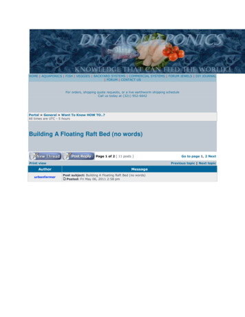
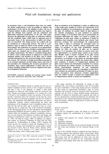
96POULOSAlternative design philosophiesRandolph (1994) has de ned clearly three different designphilosophies with respect to piled rafts:(a) the conventional approach', in which the piles are designedas a group to carry the major part of the load, while makingsome allowance for the contribution of the raft, primarily toultimate load capacity(b) creep piling', in which the piles are designed to operate ata working load at which signi cant creep starts to occur,typically 70 80% of the ultimate load capacity; suf cientpiles are included to reduce the net contact pressurebetween the raft and the soil to below the preconsolidationpressure of the soil.(c) differential settlement control, in which the piles are locatedstrategically in order to reduce the differential settlements,rather than to reduce the overall average settlementsubstantially.In addition, there is a more extreme version of creep piling, inwhich the full load capacity of the piles is utilised: that is, someor all of the piles operate at 100% of their ultimate loadcapacity. This gives rise to the concept of using piles primarilyas settlement reducers, while recognising that they also contribute to increasing the ultimate load capacity of the entirefoundation system.Clearly, the latter three approaches are most conducive toeconomical foundation design, and will be given special attention herein. However, the design methods to be discussed allowany of the above design philosophies to be implemented.Figure 1 illustrates, conceptually, the load settlement behaviour of piled rafts designed according to the rst two strategies.Curve 0 shows the behaviour of the raft alone, which in thiscase settles excessively at the design load. Curve 1 representsthe conventional design philosophy, for which the behaviour ofthe pile raft system is governed by the pile group behaviour,and which may be largely linear at the design load. In this case,the piles take the great majority of the load. Curve 2 representsthe case of creep piling, where the piles operate at a lowerfactor of safety but, because there are fewer piles, the raftcarries more load than for curve 1. Curve 3 illustrates theCurve 0:Raft only (settlement excessive)Curve 1:Raft with pile designed for conventional safety factorCurve 2:Raft with piles designed for lower safety factorCurve 3:Raft with piles designed for full utilization of capacitystrategy of using the piles as settlement reducers, and utilisingthe full capacity of the piles at the design load. Consequently,the load settlement may be non-linear at the design load, butnevertheless the overall foundation system has an adequatemargin of safety, and the settlement criterion is satis ed. Therefore the design depicted by curve 3 is acceptable, and is likelyto be considerably more economical than the designs depictedby curves 1 and 2.Favourable and unfavourable circumstances for piled raftsThe most effective application of piled rafts occurs when theraft can provide adequate load capacity, but the settlement and/or differential settlements of the raft alone exceed the allowablevalues. Poulos (1991) has examined a number of idealised soilpro les, and has found that the following situations may befavourable:(a) soil pro les consisting of relatively stiff clays(b) soil pro les consisting of relatively dense sands.In both circumstances, the raft can provide a signi cant proportion of the required load capacity and stiffness, with the pilesacting to boost' the performance of the foundation, rather thanproviding the major means of support.Conversely, there are some situations that are unfavourable,including:(a) soil pro les containing soft clays near the surface(b) soil pro les containing loose sands near the surface(c) soil pro les that contain soft compressible layers atrelatively shallow depths(d ) soil pro les that are likely to undergo consolidationsettlements(e) soil pro les that are likely to undergo swelling movementsdue to external causes.In the rst two cases, the raft may not be able to providesigni cant load capacity and stiffness, while in the third case,long-term settlement of the compressible underlying layers mayreduce the contribution of the raft to the long-term stiffness ofthe foundation. The latter two cases should be treated withconsiderable caution. Consolidation settlements (such as thosedue to dewatering or shrinking of an active clay soil) may resultin a loss of contact between the raft and the soil, thus increasing the load on the piles, and leading to increased settlement ofthe foundation system. In the case of swelling soils, substantialadditional tensile forces may be induced in the piles because ofthe action of the swelling soil on the raft. Theoretical studies ofthese latter situations have been described by Poulos (1993) andSinha & Poulos (1999).1THE DESIGN PROCESS2Piles and lowablesettlementSettlementFig. 1. Load settlement curves for piled rafts according to variousdesign philosophiesIt is suggested that a rational design process for piled raftsinvolves three main stages:(a) a preliminary stage to assess the feasibility of using a piledraft, and the required number of piles to satisfy designrequirements(b) a second stage to assess where piles are required and thegeneral characteristics of the piles(c) a nal detailed design stage to obtain the optimum number,location and con guration of the piles, and to compute thedetailed distributions of settlement, bending moment andshear in the raft, and the pile loads and moments.The rst and second stages involve relatively simple calculations, which can usually be performed without a complexcomputer program. The detailed stage will generally demandthe use of a suitable computer program that accounts in arational manner for the interaction among the soil, raft andpiles. The effect of the superstructure may also need to beconsidered.
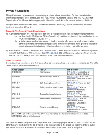
PILED RAFT FOUNDATIONSPreliminary design stageIn the preliminary stage, it is necessary rst to assess theperformance of a raft foundation without piles. Estimates ofvertical and lateral bearing capacity, settlement and differentialsettlement may be made via conventional techniques. If the raftalone provides only a small proportion of the required loadcapacity, then it is likely that the foundation will need to bedesigned with the conventional philosophy, so that the functionof the raft is merely ro reduce the piling requirements slightly.If, however, the raft alone has adequate or nearly adequate loadcapacity, but does not satisfy the settlement or differentialsettlement criteria, then it may be feasible to consider the useof piles as settlement reducers, or to adopt the creep piling'approach.For assessing vertical bearing capacity, the ultimate loadcapacity can generally be taken as the lesser of the followingtwo values:(a) the sum of the ultimate capacities of the raft plus all thepiles(b) the ultimate capacity of a block containing the piles and theraft, plus that of the portion of the raft outside the peripheryof the piles.For estimating the load settlement behaviour, an approachsimilar to that described by Poulos & Davis (1980) can beadopted. However, a useful extension to this method can bemade by using the simple method of estimating the load sharingbetween the raft and the piles, as outlined by Randolph (1994).The de nition of the pile problem considered by Randolph isshown in Fig. 2. Using his approach, the stiffness of the piledraft foundation can be estimated as follows:K pr Kp K r (1 ÿ ácp )1 ÿ á2cp Kr Kp(1)where Kpr stiffness of piled raft; Kp stiffness of the pilegroup; Kr stiffness of the raft alone; and ácp raft pile interaction factor.The raft stiffness, K r , can be estimated via elastic theory, forexample using the solutions of Fraser & Wardle (1976) orMayne & Poulos (1999). The pile group stiffness can also beestimated from elastic theory, using approaches such as thosedescribed by Poulos & Davis (1980), Fleming et al. (1992) orPoulos (1989). In the latter cases, the single pile stiffness iscomputed from elastic theory, and then multiplied by a groupstiffness ef ciency factor, which is estimated approximatelyfrom elastic solutions.The proportion of the total applied load carried by the raft isK r (1 ÿ ácp )Pr X Pt K p K r (1 ÿ ácp )97The raft pile interaction factor, ácp , can be estimated asfollows:ácp 1 ÿln(rc r0 )æ(3)where rc average radius of pile cap (corresponding to an areaequal to the raft area divided by number of piles); r0 radiusof pile; æ ln(rm r0 ); rm f0:25 î[2:5r(1 ÿ í) ÿ 0:25] 3 L;î Esl Esb ; r Esav Esl ; í Poisson's ratio of soil; L pilelength; Esl soil Young's modulus at level of pile tip; Esb soil Young's modulus of bearing stratum below pile tip; andEsav average soil Young's modulus along pile shaft.The above equations can be used to develop a tri-linearload settlement curve, as shown in Fig. 3. First, the stiffness ofthe piled raft is computed from equation (1) for the number ofpiles being considered. This stiffness will remain operative untilthe pile capacity is fully moblised. Making the simplifyingassumption that the pile load mobilisation occurs simultaneously, the total applied load, P1 , at which the pile capacity isreached is given byPupP1 (4)1ÿ Xwhere Pup ultimate load capacity of the piles in the group;and X proportion of load carried by the piles (equation (2)).Beyond that point (point A in Fig. 3), the stiffness of thefoundation system is that of the raft alone (K r ), and this holdsuntil the ultimate load capacity of the piled raft foundationsystem is reached (point B in Fig. 3). At that stage, the load settlement relationship becomes horizontal.The load settlement curves for a raft with various numbers ofpiles can be computed with the aid of a computer spreadsheet or amathematical program such as MATHCAD. In this way, it issimple to compute the relationship between the number of pilesand the average settlement of the foundation. Figure 4 shows theresults of a typical set of calculations of both settlement and factorof safety with respect to vertical bearing capacity as a function ofthe number of piles. Such calculations provide a rapid means ofassessing whether the design philosophies for creep piling or fullpile capacity utilisation are likely to be feasible.Second stage of design: assessment of piling requirementsMuch of the existing literature does not consider the detailedpattern of loading applied to the foundation, but assumesuniformly distributed loading over the raft area. While this maybe adequate for the preliminary stage described above, it is notadequate for considering in more detail where the piles should(2)where Pr load carried by the raft; Pt total applied load.rcPuBEso EsavEslEsbLoadYoung's modulus, EsP1SoilBearingstratumALd 2roPile raftelasticDepthFig. 2. Simpli ed representation of pile raft unitPile capacity fully utilized,raft elasticPile raftultimate capacityreachedSettlementFig. 3. Simpli ed load settlement curve for preliminary analysis
98POULOS(d ) if the local settlement below the column exceeds theallowable value.0·10To estimate the maximum moment, shear, contact pressure andlocal settlement caused by column loading on the raft, use canbe made of the elastic solutions summarised by Selvadurai(1979). These are for the ideal case of a single concentratedload on a semi-in nite elastic raft supported by a homogeneouselastic layer of great depth, but they do at least provide arational basis for design. It is also possible to transformapproximately a more realistic layered soil pro le into anequivalent homogeneous soil layer by using the approach described by Fraser & Wardle (1976). Figure 5 shows the de nition of the problem addressed, and a typical column for whichthe piling requirements (if any) are being assessed.Settlement: m0·090·080·070·060163248Number of piles(a)6480Maximum moment criterion. The maximum moments M x andM y below a column of radius c acting on a semi-in nite raft aregiven by the following approximations:Factor of safety5M x A x :P(5a)M y B y :P(5b)where A x A ÿ 0:0928 ln(c a); B y B ÿ 0:0928 ln(c a); A, B coef cients depending on ä a; distance of the columncentre line from the raft edge; a characteristic length of raft t[Er (1 ÿ í2s ) 6Es (1 ÿ í2r )]1 3 ; t raft thickness; Er raftYoung's modulus; Es soil Young's modulus; ír raft Poisson'sratio; and ís soil Poisson's ratio. The coef cients A and B areplotted in Fig. 6 as a function of the relative distance x a.The maximum column load, Pcl , that can be carried by theraft without exceeding the allowable moment is then given by4Pcl Mdlarger of A x and B y(6)302040Number of piles(b)6080Fig. 4. Typical results from MATHCAD analysis: (a) settlement, (b)factor of safety plotted against number of pileswhere M d design moment capacity of raft.Maximum shear criterion. The maximum shear, Vmax , below acolumn can be expressed as(P ÿ qðc2 )cq(7)2ðcwhere q contact pressure below raft; c column radius; andcq shear factor, plotted in Fig. 7.Thus if the design shear capacity of the raft is Vd themaximum column load, Pc2 , that can be applied to the raft isVmax (a) if the maximum moment in the raft below the columnexceeds the allowable value for the raft(b) if the maximum shear in the raft below the column exceedsthe allowable value for the raft(c) if the maximum contact pressure below the raft exceeds theallowable design value for the soilPcxRaft E r, νsPc2 Vd 2ðc qd ðc2cq(8)0·2B0·1Moment factors A, Bbe located when column loadings are present. This sectionpresents an approach that allows for an assessment of themaximum column loadings that may be supported by the raftwithout a pile below the column.A typical column on a raft is shown in Fig. 5. There are atleast four circumstances in which a pile may be needed belowthe column:0x–0·10AtSoil: Es, νs(very deep layer)Fig. 5. De nition of problem for an individual column loadPLoadlocation–0·200·050·10x /aFig. 6. Moment factors A, B for circular column0·15
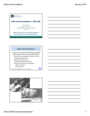
PILED RAFT FOUNDATIONS0·7Shear force, cq2·0Settlement below load S (ω (1–ν2s )P �3x /a0·40·50·6Loadlocation0·1Maximum contact pressure criterion. The maximum contactpressure on the base of the raft, qmax , can be estimated asfollows:qPqmax 2(9)awhere q factor plotted in Fig. 8, and a characteristic lengthde ned in equation (5). The maximum column load, Pc3 , thatcan be applied without exceeding the allowable contact pressureis thenqu a2Fs: q(10)where qu ultimate bearing capacity of soil below raft, andFs factor of safety for contact pressure.Local settlement criterion. The settlement below a column(considered as a concentrated load) is given byS ù(1 ÿ í2s )PEs: a(11)where ù settlement factor plotted in Fig. 9. This expressiondoes not allow for the effects of adjacent columns on thesettlement of the column being considered, and so is a localsettlement that is superimposed on a more general settlement bowl'.If the allowable local settlement is Sa , then the maximumcolumn load, Pc4 , so as not to exceed this value isPc4 Sa Es aù(1 ÿ í2s )(12)000·51·0x /a1·5Contact pressure below load q q (P /a 2)Assessment of pile requirements for a column location. If theactual design column load at a particular location is Pc , then apile will be required if Pc exceeds the least value of the abovefour criteria. That is, ifPc . Pcritx0P0·6Loadlocation0·40·200·5Fig. 8. Contact pressure factor, q1·0x /a1·5(13)where Pcrit minimum of Pc1 , Pc2 , Pc3 or Pc4.If the critical criterion is maximum moment, shear or contactpressure (i.e. Pcrit is Pc1 , Pc2 or Pc3 ), then the pile should bedesigned to provide the de ciency in load capacity. Burland(1995) has suggested that only about 90% of the ultimate pileload capacity should be considered as being mobilised below apiled raft system On this basis, the ultimate pile load capacity,Pud , at the column location is then given byPud 1:11Fp (Pc ÿ Pcrit )(14)where Fp factor of safety for piles. When designing the pilesas settlement reducers, Fp can be taken as unity.If the critical criterion is local settlement, then the pileshould be designed to provide an appropriate additional stiffness. For a maximum local settlement of Sa , the target stiffness,Kcd , of the foundation below the colomn isPcK cd (15)SaAs a rst approximation, using equation (1), the required pilestiffness, Kp , to achieve this target stiffness can be obtained bysolving the following quadratic equation:(16)where ácp raft pile interaction factor, and K r stiffness ofraft around the column. ácp can be computed from equation (3),while the raft stiffness, K r , can be estimated as the stiffness ofa circular foundation having a radius equal to the characteristiclength, a (provided that this does not lead to a total raft areathat exceeds the actual area of the raft).1·00·82·0Fig. 9. Settlement factor, ù (soil assumed to be homogeneous andvery deep)K 2p Kp [K r (1 ÿ 2ácp ) ÿ K cd ] á2cp K r K cd 01·20P0·2where qd design allowable bearing pressure below raft.Pc3 x0·30Fig. 7. Shear factor, cq , for circular columnq992·0Example of critical column loads. To illustrate the maximumcolumn loads that are computed by the approach outlined, above,an example has been considered in which a raft of thickness t islocated on a deep clay layer having a Young's modulus Es .Typical design strengths and steel reinforcement are adopted forthe concrete of the raft (see Fig. 10), and design values ofmaximum moment and shear have been computed accordingly.The design criterion for maximum contact pressure has beentake to be a factor of safety, Fs , of 1 2, while the local settlementis to be limited to 20 mm. An interior column, well away fromthe edge of the raft, is assumed.
100POULOS20Maximum load Pc2: MNMaximum load Pc1: MN10Values of Es: MPa50525100Values of Es: MPa1050100(a)(b)1010Values of pur: MPa(Es 33 pur)Maximum load Pc4: MNMaximum load Pc3: MNValues of Es: MPa1·500·75500·3000·5Raft thickness: m1·0(c)5025510000·5Raft thickness: m1·0(d)Fig. 10. Example of maximum column loads for various criteria (internal columns): (a) maximum moment criterion; (b)maximum shear criterion; (c) maximum contact pressure criterion (FS 1 2); (d) maximum local settlement criterion(20 mm maximum). Concrete: f c 32 MPa; Er 25 000 MPa. Steel: f y 400 MPa; 1% reinforcementFigure 10 shows the computed maximum loads for the fourcriteria, as a function of raft thickness and soil Young's modulus. The following observations are made:(a) For all design criteria, the maximum column load that maybe sustained by the raft alone increases markedly withincreasing raft thickness.(b) The maximum column loads for bending moment and shearrequirements are not very sensitive to the soil Young'smodulus, whereas the maximum column loads for thecontact pressure and local settlement criteria are highlydependent on soil modulus.(c) For the case considered, the criteria most likely to becritical are the maximum moment and the local settlement.Although the results in Fig. 10 are for a hypothetical case, theynevertheless give a useful indication of the order of magnitudeof the maximum column loads that the raft can sustain and therequirements for piles that may need to be provided at a columnlocation. For example if a 0 5 m thick raft is located on a soilwith Young's modulus of 25 MPa, the lowest value of columnload is found to be about 2 8 MN (this occurs for the maximummoment criterion). If the actual column load is 4 MN, then fromequation (14), if Fp is taken as unity, the required ultimate loadcapacity of the pile would be 1 11 (4:0 ÿ 2:8) 1:33 MN.Detailed design stageOnce the preliminary stage has indicated that a piled raftfoundation is feasible, and an indication has been obtained ofthe likely piling requirements, it is neccessary to carry out amore detailed design in order to assess the detailed distributionof settlement and decide upon the optimum locations andarrangement of the piles. The raft bending moments and shears,and the pile loads, should also be obtained for the structuraldesign of the foundation.Several methods of analysing piled rafts have been developed, and some of these have been summarised by Poulos et al.(1997). The less simpli ed methods of numerical analysis tendto fall into the following categories:(a) methods employing a strip on springs' approach, in whichthe raft is represented by a series of strip footings, and thepiles are represented by springs of appropriate stiffness (e.g.Poulos, 1991)(b) methods employing a plate on springs' approach, in whichthe raft is represented by a plate and the piles by springs(e.g. Clancy & Randolph, 1993; Poulos, 1994a; Russo &Viggiani, 1998; Viggiani, 1998; Yamashita et al., 1998;Anagnostopoulos & Georgiadis, 1998)(c) boundary element methods, in which both the raft and thepiles within the system are discretised, and use is made ofelastic theory (e.g. Butter eld & Banerjee, 1971; Kuwabara,1989, Sinha, 1997)
PILED RAFT FOUNDATIONS(d ) methods combining boundary element analysis for the pilesand nite element analysis for the raft (e.g. Hain & Lee,1978; Ta & Small, 1996; Franke et al., 1994)(e) simpli ed nite element analyses, usually involving therepresentation of the foundation system as a plane strainproblem (Desai, 1974) or an axisymmetric problem(Hooper, 1974)( f ) three-dimensional nite element analyses (e.g. Zhuang etal., 1991; Lee, 1993; Wang, 1995 (personal communication); Katzenbach et al., 1998).Poulos et al. (1997) have compared some of these methodswhen applied to the idealised hypothetical problem shown inFig. 11. Six methods have been used:(a) Poulos & Davis (1980)(b) Randolph (1994)(c) strip on springs analysis, using the program GASP (Poulos,1991)(d ) plate on springs approach, using the program GARP(Poulos, 1994a)(e) nite element and boundary element method of Ta & Small(1996)( f ) nite element and boundary element method of Sinha(1996).Figure 12 compares the computed characteristics of behaviourof a raft supported by nine piles, one under each column, withthe overall factor of safety at the design load being 2 15. Theapplied load exceeds the ultimate capacity of the piles alone,and there is therefore some non-linear behaviour. Despite somedifferences between the various methods, most of those thatincorporate non-linear behaviour give somewhat similar results,although there are signi cant differences among the computedraft bending moments. However, it would appear that, providedthe analysis method is soundly based and takes into account theBearing capacity of raft 0·3 MPaLoad capacity of each pile 0·873 MN (compression) 0·786 MN (tension)yAP1AAP2P1P1AP1xAP22Ep Er 30 000 MPaνp νr 0·2P12P12211P2P1tr 0·5 ml 10 mE 20 MPaν 0·3d 0·5 ms 222limited load capacity of the piles, similar results may beexpected for similar parameter inputs.SOME CHARACTERISTICS OF BEHAVIOURIn order to examine some of the characteristics of piled raftbehaviour, a more detailed study has been made of the hypothetical case shown in Fig. 11. The standard' parameters shown inFig. 11 have been adopted, but consideration has been given tothe effects of variations in the following parameters on foundation behaviour
The third is a detailed design phase in which a more refined analysis is employed to confirm the optimum number and location of the piles, and to obtain essential information for the structural design of the founda-tion system. The selection of design geotechnical parameters is an essential comp