Transcription
AAIB Bulletin: 10/2019G-PERHEW/C2018/06/03ACCIDENTAircraft Type and Registration:Guimbal Cabri G2, G-PERHNo & Type of Engines:1 Lycoming O-360-J2A piston engineYear of Manufacture:2016 (Serial no: 1164)Date & Time (UTC):8 June 2018 at 1433 hrsLocation:Goodwood Aerodrome, SussexType of Flight:TrainingPersons on Board:Crew - 2Passengers - NoneInjuries:Crew - 2 (Serious)Passengers - N/ANature of Damage:Damaged beyond economic repairCommander’s Licence:Commercial Pilot’s LicenceCommander’s Age:59 yearsCommander’s Flying Experience:8,9201 hours (of which 69 were on type)Last 90 days - 30 hoursLast 28 days - 7 hoursInformation Source:AAIB Field InvestigationSynopsisWhile conducting a Simulated Engine Failure from the Hover (SEFH) the helicopter yawedrapidly to the left. Despite the actions of the pilots the helicopter continued to yaw rapidly,and control was not recovered. The helicopter was seen to climb while spinning beforedescending rapidly and contacting the ground, sustaining severe damage. Both occupantssuffered serious injuries.The manufacturer has subsequently issued service letter SL 19-001, Throttlemanagement during simulated engine failure, and SL 19-002, Controllability in yaw atlow rotor speed.History of the flightOn the day of the accident the commander and a student pilot were conducting a PPL(H)skills test; they were in the helicopter’s left and right seats respectively.The helicopter departed Goodwood Aerodrome at about 1300 hrs for a navigationexercise and then returned to the aerodrome to complete the remaining exercises,which included an SEFH. The SEFH was completed to a satisfactory standard, butFootnote1The commander’s total flying hours are a combination of fixed and rotary wing hours, with 4,420 rotary winghours. Crown copyright 201929All times are UTC
AAIB Bulletin: 10/2019G-PERHEW/C2018/06/03the commander noted that the helicopter yawed slightly to the right2. At the time theweather was fine with the wind from about 050 at 5 kt.Once all the required exercises had been completed the commander asked the studentwhether there was anything else he would like to do. He asked if he could attempt anotherSEFH, as he felt he was able to fly the manoeuvre to a better standard; the commanderagreed.The student commented that during the subsequent SEFH, he recognised the helicopterstarting to yaw to the right and applied left pedal to counteract this, after which the aircraftbegan to descend gently. His intention was to raise the collective to cushion the landingat about 1.5 ft agl. However, the helicopter started to rapidly yaw left. He applied full rightpedal before handing control to the commander, who was already on the controls with fullright pedal applied. The commander believes she moved the cyclic forward slightly to tryto keep the helicopter level, but she could not remember what collective inputs she mayhave made. Witnesses in the control tower saw the helicopter spin and climb to about40 ft agl, before descending and contacting the ground.Once the helicopter had come to rest the commander secured it. The airfield’s emergencyresponse vehicles quickly arrived on the scene. They were followed shortly thereafter bylocal authority ambulances. Both pilots were seriously injured and, after being extractedfrom the helicopter, were taken to hospital by road.Pilots’ commentsStudent pilotThe student pilot stated that the first SEFH landing felt “a bit firm” to him and he felt he coulddo better, so he took the opportunity to repeat the manoeuvre.On the accident SEFH, after the helicopter start to yaw rapidly to the left, he also felt it climb.He felt that the application of the right pedal did cause the rate of left yaw to slow down.He tried to keep the helicopter steady with the cyclic but did not recall handing control tothe commander. He reported that the forces involved were so violent that he was forcedsideways to his right.He added that he is “reactive” to the yaw during engine-off exercises and waits for the yawto commence before applying the appropriate pedal to counteract it.Footnote2The Cabri G2’s main rotor blades rotate in a clockwise direction when viewed from above. The torque effectis a tendency of the main rotor to yaw the fuselage in the opposite direction from the rotor. The tail rotorprovides thrust to counteract this. After an engine failure the torque effect is reduced, resulting in a tendencyfor the helicopter to yaw in the direction of the main rotor blades, to the right in a Cabri G2. Hence some leftpedal is required after the failure. Crown copyright 201930All times are UTC
AAIB Bulletin: 10/2019G-PERHEW/C2018/06/03CommanderThe commander stated that for a SEFH, once the student had established the helicopter ina stable hover, at approximately 7 feet agl, she announces “engine failure in 3, 2, 1, GO”.On “GO” she closes the throttle ensuring it goes through the detent3.The commander stated the student had been a bit slow in applying the left pedal on the firstSEFH. She believes that on the accident SEFH, she had not fully closed the throttle beforethe helicopter started to yaw to the left and thinks the student may have anticipated the leftpedal and applied it before she said “GO” and the throttle was closed.Instructor’s commentsThe student’s instructor, who had flown the six instructional flights with him prior to theaccident, commented that the student was very conscientious and always well prepared. Headded that he could, at times, “over-analyse” some of his performances and be excessivelycritical on himself despite the skills demonstrated being generally of an acceptable standard.Helicopter’s Flight ManualSection 4 of the Cabri G2’s Flight Manual, Normal Procedures, states:‘Training Power failure in hover in ground effect practice1. Roll-off throttle frankly4 until on its stop,2. Counteract yaw motion by applying left pedal,3. Increase collective as ground approaches, to smooth landing,4. Push collective down once landed.Note 1: If the helicopter is light, it may bounce after a first touchdown.Note 2: The Cabri G2 has no natural tendency to depart in roll or pitch afterfailure. No systematic corrective cyclic action is needed.A slight forward motion at impact is recommended for better control.Note 3: For a forgiving practice, respect a maximum of 5 feet height. ’Footnote34See Helicopter information for a description of the Cabri G2’s throttle.The manufacturer commented that ‘frankly’ means that the throttle should be closed in one motion andwithout hesitation. Crown copyright 201931All times are UTC
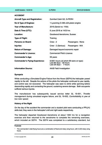
AAIB Bulletin: 10/2019G-PERHEW/C2018/06/03Accident siteThe accident site occurred in the Helicopter Training Area at Goodwood Aerodrome. Thehelicopter came to rest upright with the right side of the fuselage in contact with the groundand pointing in a north-east direction. The landing gear had penetrated the fuselage on theleft side and the right passenger door had broken and become detached. The fenestrontail rotor had detached from the tail boom and there was evidence that two of the main rotorblades had struck the ground (Figure 1). Both landing skids had dug into the ground withno evidence of movement after contact.Figure 1G-PERH at the accident siteHelicopter informationThe Guimbal Cabri G2 is a light two-seat helicopter primarily used to train private pilots andfor aerial photography and observation. It is the first helicopter to be primarily certified toEASA CS27 and then to achieve FAA FAR-27 certification for helicopters with a maximumtakeoff weight of less than 3,175 kg (7,000 lbs).The airframe is composed of three sections; main fuselage, engine section, and tail boom.The main fuselage is a carbon-fibre reinforced monocoque, constructed in five parts. Inthe cabin there are two side-by-side seats, with the pilot occupying the right position. Themain fuselage also includes a central structure, baggage compartment and fuel tank. Theengine section is isolated from the cabin by a firewall with the engine supported on a tubularsteel frame. The composite tail boom incorporates a Fenestron tail rotor, vertical fin and ahorizontal stabilizer.The landing gear is composed of two tubular bows with skids. It is attached to the fuselageby soft elastomeric mounts, to avoid potential ground resonance problems. The landinggear is designed to withstand vertical landing loads combined with smaller longitudinal andlateral loads. Crown copyright 201932All times are UTC
AAIB Bulletin: 10/2019G-PERHEW/C2018/06/03SeatsThe seats have been designed to reduce the forces on the passengers in the event ofan impact and are capable of absorbing loads up to 19 g forward and up to 30 g vertical,which corresponds to a free fall rate of about 10 m/sec (2,000 ft/min). The seats comprisea composite shell with minimal cushioning added for comfort. The seat shell is attachedto the bulkhead by two seat rails, which allow it to move vertically and is restrained by anenergy absorbing strut (Figure 2).Seat railsEnergyabsorbingstrutFigure 2Left seat composite shell and seat rails with energy absorbing strutEngine and controllersThe helicopter is powered by a four-cylinder, air-cooled Lycoming O-360-J2A engine. Itis installed aft of the main gearbox, with its crankshaft facing forward and is supported onelastomeric vibration mounts.To reduce pilot workload the helicopter is equipped with an electronic engine governor tomaintain the engine at the nominal speed regardless of power demand. The governorregulates the engine speed to 2,650 rpm using data from an engine speed pickup, rotorspeed pickup and the throttle position. If the engine speed is commanded to below 2,000 rpm(such as for shutdown) the engine governor disengages but will re-engage and acceleratethe engine to the nominal running speed once the speed is above 2,000 rpm.The engine throttle control is on the collective lever and is operated by a conventionaltwist-grip (Figure 3). The twist grip rotates a shaft which, through a system of cams andlevers, operates the engine throttle cable. At the extreme clockwise rotation of the twistgrip, a detent gives the pilot a physical indication that the throttle has fully closed. A motor,controlled by the governor, is connected to the twist grip shaft and there is a friction couplingwhich allows the pilot to overcome the governor if required. A switch on the end of thecollective activates or deactivates the engine governor. Crown copyright 201933All times are UTC
AAIB Bulletin: 10/2019G-PERHEW/C2018/06/03Figure 3Engine throttle control systemCorrelation camThe output of the throttle shaft from the collective lever is connected by a linkage to acorrelation cam so that when the collective is raised the throttle will increase the enginepower. The cam profile is designed to aid the function of the engine governor and tominimise the pilot work should the governor fail. When the collective lever is raised withthe throttle twist grip fully closed, the cam profile is designed to have no effect on theengine throttle.Tail rotor effectivenessThe manufacturer commented that the main rotor can produce lift in a hover at rotorspeeds well below its authorised speed range of 515 to 540 rpm and even below 450 rpm5.However, in such a situation, the Fenestron thrust will not be sufficient to maintain effectiveyaw control and even with full right pedal, the helicopter will start spinning uncontrollablyto the left. In addition, if such a loss of control in yaw occurs, raising the collective willlower the rotor speed even more and will aggravate the situation by increasing the spinrate to the left.Footnote5450 rpm is the minimum authorised rotor speed in autorotation. Crown copyright 201934All times are UTC
AAIB Bulletin: 10/2019G-PERHEW/C2018/06/03Helicopter examinationAirframeThe airframe was subjected to a visual examination at the AAIB facilities to assess thedamage sustained during the impact. The monocoque structure was largely intact withevidence of crushing on the aft right underside. All access panels were in place except forthe luggage door and right passenger door, which was broken in two pieces. There wasevidence on the underside of penetration from the landing gear bows at both mountinglocations. The front landing gear bow had caused minor damage to the central console inthe cabin and the aft bow had penetrated the luggage bay and the fuel tank volume. Theflexible fuel tank liner had deformed around the bow without perforation and no fuel hadleaked. The Fenestron had detached from the tail boom and there was impact damage tothe tips of two main rotor blades.Following the visual examination, the helicopter was digitised using a ‘3D’ structured lightscanning system to quantify the structural deformation. All exterior surfaces were scanned,as well as the landing skids, engine bay and cabin interior. The results of the scan werethen compared with the original design data obtained from the helicopter manufacturer(Figure 4).Figure 4Digital analysis of G-PERHThe results of the scanning showed that the tail boom of the helicopter was misalignedby approximately 3 to the left of nominal and bent slightly upwards. The cabin bulkheadshowed evidence of multiple damage locations of crushing, cracking and delamination. Crown copyright 201935All times are UTC
AAIB Bulletin: 10/2019G-PERHEW/C2018/06/03Seats and attachmentsThe position of the seats was recorded with the cushions removed to enable accuratemeasurements to be taken from the composite shell (Table 1). Once the seat shells wereremoved, the length of the energy absorbing struts was measured:StrutLeftRightNominal Length302 /- 0.5 mmMeasuredLengthExtension351.6 mm49.6 mm304.5 mm2.5 mmTable 1Seat position and energy absorbing strut extensionThe right seat shell was examined, and several damage locations were identified. The leftseat was undamaged.The lower end of the right seat, outboard track was bent inwards and forwards byapproximately 20 and the lower end of the inboard track showed minor deformation. Thebend was located at the lower attachment to the seat and a witness mark was evident onthe seat shell from the track. The deformation of the right seat tracks was coincident withthe crushing deformation of the lower section of the monocoque and cabin bulkhead.Landing gearThe landing gear assembly was intact and removed from the helicopter at the accidentsite. There was evidence of bending of the tubes and local buckling at the joints. It wasnoted that the landing skids fitted to the accident helicopter were of a later modificationstandard which was introduced to prevent the bow tubes from failing, which had occurred inprevious accidents. The geometry of the landing gear assembly was measured using the3D structured light system and it was found that the right skid was straight, in accordancewith the design, whereas the left skid was curved. The aft end of the left skid was bentupwards by approximately 5 mm and was forward of the right skid by more than 350 mm.The profile of the two bows between the skids showed evidence of the right skid beingbent outwards whereas the left side showed no such deformation.Engine bayThe engine bay was covered by three composite access panels and the Lycoming engine wassupported by a steel tubular frame attached to the monocoque. The frame also supportedsome ancillary equipment and the Fenestron drive shaft. Visual examination and digitalanalysis of the frame identified several members were bent and the right lower monocoqueattachment point was deformed in the impact. The friction lining of the Fenestron drivebraking system was damaged due to misalignment of the drive shaft and it was noted thatthe main drive belt was not correctly aligned on the upper pulley. Crown copyright 201936All times are UTC
AAIB Bulletin: 10/2019G-PERHEW/C2018/06/03SurvivabilityThere are four requirements to survive a crash:1.Maintain a liveable volume for the occupant throughout the crashsequence.2.Restrain the occupant.3.Keep the crash loads experienced by each occupant within humantolerance.4.Provide time to escape. Primarily, this is time to escape a post-crash fire.The manufacturer actively markets the safety features of the Cabri G2 helicopter and itscompliance to survivability requirements of EASA CS-27 and FAA FAR-27. The carbonfibre monocoque provides a rigid structure for the protection of the occupants. In thisaccident the liveable cabin volume was not compromised, and the seat belts restrainedthe occupants. However, lateral movement of the right seat occupant during the impactsequence most probably resulted in the right passenger door being broken. It is not thoughtany injuries were sustained from this.The lack of post-crash fire meant that there was no immediate urgency to evacuate thehelicopter and the first responders were able to remove the occupants in a timely manner,limiting the potential for further injury.The energy absorbing struts in the seat system are designed to reduce the loads on theoccupants in the event of a vertical impact. The manufacturer states that in certificationtesting the ‘occupants would survive a 2000 ft/min impact, equivalent to a 5 m free fall’.In this accident the left seat strut extended to 116% whereas the right seat strut extendedto 101%. However, the injuries sustained by both occupants were similar and so it isjudged that the impact energy was absorbed by a different mechanism for the right seatoccupant.AnalysisLoss of controlThe first simulated SEFH was completed to a satisfactory standard, but the helicopter yawedslightly right and, in the student’s opinion, landed firmly. Given that the student tended toover-analyse some of his performances, could be highly self-critical and generally strivedfor excellence, it is likely he would aim for a gentler landing in any subsequent SEFH.Despite the student stating that he was reactive to the yaw in simulated engine failureexercises, it is probable that in this instance he anticipated it by applying left pedal andthen started to raise the collective to cushion the landing before the throttle was closed.The forces experienced as the helicopter was yawing rapidly may also have caused him tounintentionally raise the collective. Lifting the collective before the throttle was fully closedwould have resulted in the correlator cam increasing the engine speed until, at 2,000 rpm,the engine governor would have re-engaged. These actions would have caused an increase Crown copyright 201937All times are UTC
AAIB Bulletin: 10/2019G-PERHEW/C2018/06/03in engine speed resulting in the high rate of yaw and climb, which the student felt. Had thethrottle been fully closed the correlator cam profile would have had no effect on the enginespeed when the collective was raised.The application of right pedal not stopping the yaw to the left indicates that the rotor speedhad reduced, thus making the Fenestron less effective.Impact SequenceImmediately prior to ground impact, the helicopter was rotating with a high rate of left yaw, ina slightly nose-up attitude and rolled to the left. The first impact point was the aft end of theleft landing skid and this deformed upwards. The aft bow penetrated the fuel tank volume,but the fuel quantity was such that the liner was able to deform without rupturing. It is likelythat at this moment the left seat moved downward on the seat rails, absorbing the verticalenergy for the occupant.As the impact sequence progressed the helicopter pitched forward, and the left skid deformedfurther as it dug into the soft ground. Due to the yawing motion, the helicopter rolled to theright until the right skid contacted the ground and dug into the ground, deforming the rightside of the bow. The helicopter fuselage still had inertia in yaw and consequently it slidaround the profile of the landing gear bows until the right aft fuselage contacted the ground.As a result of this lateral motion, the lower part of the Fenestron struck the ground andapplied a torsional load at the junction to the tail boom, resulting in failure of the compositestructure. The fuselage was now inclined to the right and two of the main rotor blades hitthe ground, the impact of the second causing the engine to stop.As the aft right side of the fuselage contacted the ground, the remaining vertical energy wasabsorbed by the composite structure crushing and delaminating. This was clearly seenat the lower cabin bulkhead position and caused the right seat rails to deform. From thedirection of the deformation it was possible to deduce that the loads were predominantlylateral. This was also demonstrated by the right seat occupants contact with the right doorand the damage to the outside of the seat shell.SurvivabilityThe seats fitted to the Cabri G2 are designed to absorb only vertical energy and, alongwith seat belts, restrain the occupants in the longitudinal direction. From analysis of theimpact sequence it has been shown that the left seat occupant was subjected to verticalloads during the initial impact and the seat stroke was enough to survive the impact. Asthe accident progressed, due to the high rate of yaw, the loads became lateral in directionand so the energy absorbing seat became less influential for survivability. Further, thedeformation of the seat rails did not impede the motion of the right seat as the loadingwas predominantly lateral. The remaining energy was absorbed by the distortion of thecomposite structure which kept the loads experienced by the right seat occupant belowsurvivable limits. Crown copyright 201938All times are UTC
AAIB Bulletin: 10/2019G-PERHEW/C2018/06/03ConclusionThe accident was probably initiated by premature application of the left yaw pedal andraising the collective lever, before the throttle was fully closed during a simulated enginefailure exercise. This was probably because the student anticipated the right yaw beforethe commander had said “GO” and the throttle was fully closed.In this accident, the helicopter maintained a liveable volume for the occupants throughout theaccident sequence and the first responders were able to extricate the occupants in a timelymanner without risking further injury. The flexible fuel tank liner had not been compromisedand there was no post-crash fire. The occupant retention system did not prevent the rightseat occupant from contacting and breaking the access door, however he was retainedwithin the cabin. A combination of the energy absorbing seat system and the destructionof the composite fuselage absorbed the vertical and lateral impact energy such that bothoccupants survived the crash with injuries which were serious but not life‑threatening.Safety actionsAs a result of this, and other similar events, the manufacturer published inFebruary 2019 two Service Letters to prevent reoccurrence. They are availableon its customer support portal.SL 19-001 - Throttle management during simulated engine failure.This service letter provides an explanation of the engine governor / correlatorsystem and the need to ensure the twist grip throttle is fully closed whilstpracticing certain manoeuvres. It proves advice to flight instructors on how toposition the hand on the throttle grip to enable the throttle to be closed in onemovement and therefore ensuring the engine throttle does not open when thecollective is raised.SL 19-002 - Controllability in yaw at low rotor speed.This service letter proves advice on yaw control when operating with low rotorspeeds. It includes a list of scenarios where yaw control could be lost andmitigating actions to prevent loss of control. One scenario is Simulated EngineFailure from the Hover. When operating at low rotor speeds with full or almostfull right pedal applied it is recommended not to raise the collective but keepit as low as possible and increase forward airspeed by cyclic input, and not toincrease the rotor speed by turning the twist grip.Published 19 September 2019. Crown copyright 201939All times are UTC
Helicopter information The Guimbal Cabri G2 is a light two-seat helicopter primarily used to train private pilots and for aerial photography and observation. It is the first helicopter to be primarily certified to EASA CS27 and then to achieve FAA FAR-27 certification for helicopters with a
