Transcription
MPLEElectrical Testingand Fault FindingLearner WorkbookSAVersion 1Training and Education SupportIndustry Skills UnitMeadowbankPRODUCT CODE: 5682
Electrical Testing and Fault FindingTable of contentsIntroduction . 5References . 5Risk Assessment Terminology . 5Section 1: Regulations, Documentation and Test Equipment . 7Acts and Regulations. 7Installation work requirements . 8Construction Site Testing . 10ETypes of Test Equipment . 12Review Questions . 21MPLSection 2: Mandatory Testing / Switchboard Marking – LowVoltage Electrical Installations . 27General Introduction . 27Earth Continuity and Resistance Testing . 29Insulation Resistance Testing . 37SAPolarity Testing . 43Correct Circuit Connections – Transposition Testing . 57Correct Circuit Connections - Short Circuit Testing . 67Correct Circuit Connections – Interconnection Testing . 73Earth Fault-Loop Impedance Testing . 85Residual Current Device (RCD) - Operation Testing . 89Switchboard Marking . 93Section 3: Fault Finding Concepts . 101Introduction . 101Familiarisation With the System . 102Symptom Recognition . 104Test Equipment . 105Developed by Training & Education Support Industry Skills Unit, Meadowbank@ TAFE NSW 2012
Electrical Testing and Fault FindingLocalising a Fault . 110Preventative Action . 118Fault Analysis, Testing and Commissioning . 119Section 4: Testing Electrical Equipment and Associated Circuits 131Introduction . 131Lighting Circuit Testing & Fault Finding . 131Water Heater / Heating Appliance Testing & Fault Finding . 149Single & Three Phase Motor Testing & Fault Finding . 169Sample Assessments – Electrical Testing and Fault Finding . 191ESample Theory Test 1 . 191MPLSample Theory Test 2 . 203Answers to Review Questions. 219Section 1 . 219Section 2 . 220Section 3 . 222SASection 4 . 223Answers to Sample Theory Test 1 . 226Answers to Sample Theory Test 2 . 229Resource Evaluation Form . 235Developed by Training & Education Support Industry Skills Unit, Meadowbank@ TAFE NSW 2012
Electrical Testing and Fault FindingSection 1: Regulations, Documentation andTest EquipmentActs and RegulationsRequirements relating to testing and inspections of electrical work carried out ininstallations are covered in the various state and territory acts and regulations.Such as:Electricity Safety (Electrical Installations) Regulation, 2005 (NSW).Electricity Safety Act. 1971 - Amended (ACT).National Electricity (South Australia) Act, 1996.EElectricity Safety (Installations) Regulations, 1999 (Vic).MPLElectricity Industry Safety and Administration Regulation, 1999 (Tas).Electricity (Licensing) Regulations, 1991 (W.A.).Electricity Safety Act. 2002 (Qld).The regulations may cover all or some of the following:definitionstesting requirementscommissioning of installation worknotification of installation worknotification of test resultsqualifications of persons to carry out testingdifferent grades of electrical licensingpenalties for non compliance to safety regulationsinspection requirementsresponsibilities of installers and supply authorities.SA The aim of all state and territory Electrical regulations is to ensure the safety ofpersons, livestock and property from electrical shock, fire and physical injury fromhazards that may arise.Page 7 of 238
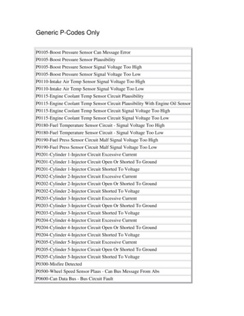
Electrical Testing and Fault FindingInstallation work requirementsCompliance:Installation work must, comply with the requirements of AS/NZS 3000 Wiring rules not be connected to the supply unless it complies with AS/NZS 3000 andany local regulations or relevant codes.Qualified Personnel:The testing must be carried out by either: the installing contractor another installing contractor an authorised person.MPLEActivity: Installation RequirementsSAComplete the following questions:1. What qualifications are required by yourstate/territory for the issue of a license toinstall and test fixed electrical installations?2. What is the penalty given to anunqualified person carrying out electricalinstallation and testing?Page 8 of 238
Electrical Testing and Fault FindingInstallation Testing:The test on the installation work must include the procedures necessary to checkthat:a. there is earth continuity and that the earth resistance is safeb. the insulation resistance is safec. polarity is correctd. there is no transposition of earth and neutral conductorse. there is no short circuit between conductorsf. there is no intermix between conductors of different circuitsg. switchboard equipment is correctly markedh. the installation will operate as intended.Visual Inspection:A visual inspection of complete electrical installations should include: EMPL main earth conductor size is correctlocation and suitability of equipment and accessories in restricted zonessuch as laundries, bathrooms, swimming pools, etc.voltage drop in all circuits is not excessivemaximum demand of circuits does not exceed the current carryingcapacity of the cablescircuit protective devices are correctly rated for current carrying capacityand fault currentmechanical protection is adequate where requiredswitchboard markings are correct including neutral conductor identificationfixing and supports are adequatefinal sub-circuits are used for appliancesthe number of points per final sub-circuit is not excessiveRCDs are installed on the required circuitsequipotential bonds are installed and of correct sizeenvironmental considerations such as heat, chemicals, etc are taken intoconsideration.SA Testing and Tagging:The WH&S Acts of all stages and territories place a duty of care to provide a safework place. To meet this duty of care, testing and tagging of electrical equipmentis required.Inspection and testing needs to be in accordance with the performancespecifications of: AS/NZS 3760:2010, In-Service Safety Inspection and Testing of Electrical EquipmentAS/NZS 3012:2010, Electrical Installations - Construction and Demolition SitesAS/NZS 3002:2008, Electrical Installations - Shows and CarnivalsPage 9 of 238
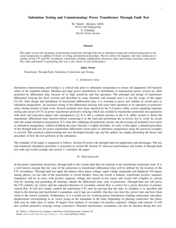
Electrical Testing and Fault FindingConstruction Site TestingConstruction site wiring must meet the same standard as wiring in a completedbuilding. In addition the following tests are required on electrical equipment:all construction wiring, switchboards and wiring within relocatablestructures must be tested prior to connection to the supply and re-testedevery six (6) months portable safety switches must have a daily pushbutton test before use andthen every three (3) months fixed safety switches must have a monthly pushbutton test and then everytwelve (12) months all plant, electrical equipment and flexible electrical cords should beinspected for wear and mechanical damage and tested for earth continuityand insulation resistance prior to first use, and every three (3) monthsthereafter.E MPLAll inspections must be carried out by a competent person, all equipment must betagged, and a record of inspection and tests kept.The details recorded shall include: the date of inspection plant number of the item inspected licence number and signature of the inspecting electrician any repairs required as a result of the inspection.SAThe following tables indicate the testing and inspection intervals for various workenvironments.Table 1 Description of Classes of Work EnvironmentsClass of WorkEnvironments1. Manufacturing,repair work2. Construction anddemolition sites3. Officeenvironment4. Commercialenvironments5. Hire equipmentindustryPage 10 of 238Examples of Equipment / EnvironmentsFactories, workshops, repair centres, assembly,maintenance, fabrication.Construction and demolition sites, office refurbishment,supplying equipment services to construction sites, forexample electrical or plumbing.Office environment where equipment is not subject toconstant flexing of the supply cords. For examplecomputers which are used in a fixed position.Laboratories, tea rooms office kitchenettes, kitchens,schools, cleaning, and where equipment is subject toconstant flexing of the supply cord.Hire of equipment or similar contract (leased equipment).
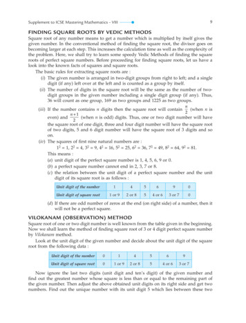
Electrical Testing and Fault FindingTable 2 Frequency of Inspection and Tests of all ElectricalEquipment Other Than Fixed EquipmentClass of EquipmentClass ofWorkClass 1Class 2(protectivelyearthed)(doubleinsulated)Additional Testing forRCDsPushbutton testTest foroperation(by user)CordExtensionSets &ElectricalPortableOutletDevices(EPODs)6 months3 months3.Office5 years5.HireEquip.3 monthsEach day3 months5 years3 months2 years5 years2 years3 months12 months12 months3 months orbefore everyuse,whichever isthe longerBefore eachhireBefore eachhireBefore eachhireBeforeeach hireBeforeeach hireDaily, orbefore everyuse,whichever isthe longer12 months6 months6.Shows/Carnivals6 monthsImmediatelyafterconnectionto a socketoutlet andevery day inuseSACommercial12 monthsMPL2.Construction &Demol’n(seeAS/NZS3012)4.12 monthsDaily, orbefore everyuse,whichever isthe longerE1.Manufacturing6 months12 monthsPage 11 of 238
Electrical Testing and Fault FindingTypes of Test EquipmentGeneral InformationWhen testing any electrical installation, it is important to: identify suitable test equipment which can be used to confirm that aninstallation meets prescribed requirements check essential test equipment to determine instrument accuracy onknown loads maintain test equipment in a safe and operational working condition confirm that the readings taken using essential test equipment are withina range of expected values for typical load conditions list the required periodic inspection and tests that show workplaceequipment is safe to use. insulation/continuity resistance testerohmmeter - ohms range of a multimeter - capable of displaying accuratereadings in the range between 0.5 and 5 ohms.series (400 V/230 V) test lampsRCD testerfault loop impedance tester.MPL EThe essential instruments needed for testing that an electrical installationcomplies with the requirements of electrical safety regulations are as follows:Additional instruments useful in testing are:voltmeter - voltage range of a multimeter or clip-on ammeterneon testerphase sequence indicatorclamp-on ammeter (tong tester).SA Accessories used in testing procedures include: a fluorescent lamp starter, base wired and with insulated alligator clip.a 15 W lamp and 40 W lamp wired with insulated alligator clips. These areused as known loads.a trailing lead of known resistance - 100 m flexible cable fitted at one endwith an insulated alligator clip and the other with a plug suitable forconnecting to test instruments.a resistance calibration panel for checking instrument accuracy. Suggestresistance values:for earth resistance testing - 0.5 Ω, 1 Ω and 2 Ω at 1% tolerance 1 Wfor typical loads - 10 Ω, 15 Ω, 20 Ω and 50 Ω at 1% tolerance 1 Wfor insulation resistance - 10 kΩ, 1 MΩ and 10 MΩ at 1% tolerance 1 Wtemporary test bridges - short lengths, say 300 mm, of flexible cable fittedwith insulated alligator clips.Page 12 of 238
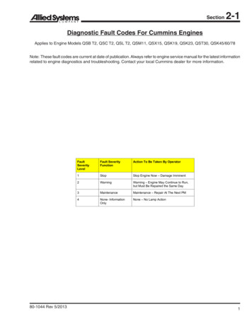
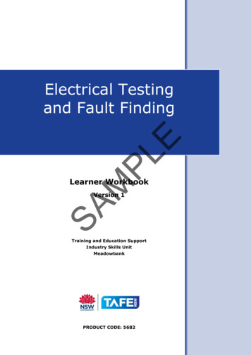
Electrical Testing and Fault FindingTest Equipment InformationINSULATION RESISTANCE TESTERDescriptionAS/NZS 3000:2007 Wiring Rules – Clause 8.3.6 requires insulation resistance tobe measured by applying a d.c. voltage of 500 V. As an electrician you may berequired to use a 500 V or 1000 V insulation resistance tester (sometimesreferred to as “megger”) which can be a hand driven generator type or apushbutton electronic type. These instruments may also include ohmmeter orcontinuity test functions.The AS/NZS 3000:2007 Wiring Rules requirements for low voltage wiring systemsis to have a minimum insulation resistance of 1 megaohm between all liveconductors and earth, and 10,000 ohms for low voltage equipment with asheathed heating element such as found on stoves and water heaters.EUseMPLSome important points to remember when using insulation resistance testers:although the instrument may not be able to deliver enough energy tocause a fatality it can give a nasty shock capable of causing a secondaryaccident such as falling from a ladder a 500V/1000V testing voltage can cause electrical damage if applied tosolid state/electronic equipment or apparatus (e.g. electronic controlpanels or light dimmers) an insulation resistance tester must only be used on wiring disconnectedfrom the supply, i.e. DEAD testing.SA As insulation resistance testers age there may be a deterioration of componentssuch as the strength of permanent magnet fields in a hand driven type or achange in circuit component values in the electronic type. This can result in adecrease in the nominal test voltage to well below the instruments rated value.It is important that your insulation resistance tester measures resistanceaccurately if you are to ensure the installation you test complies with therequirements.The insulation resistance tester must maintain its terminal voltage within 20%and -10% of the nominal open circuit terminal voltage, when measuring aresistance of 1 MΩ on the 500 V range.Page 13 of 238
AS/NZS 3000:2007 Wiring Rules – Clause 8.3.6 requires insulation resistance to be measured by applying a d.c. voltage of 500 V. As an electrician you may be required to use a 500 V or 1000 V insulation resistance tester (sometimes referred to as