Transcription
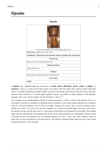
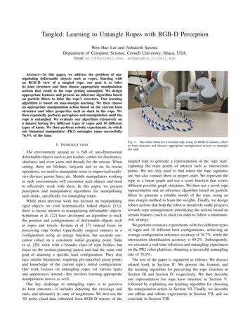
Tangled: Learning to Untangle Ropes with RGB-D PerceptionWen Hao Lui and Ashutosh Saxena.Department of Computer Science, Cornell University, Ithaca, USA.Email: wl378@cornell.edu, asaxena@cs.cornell.eduAbstract— In this paper, we address the problem of manipulating deformable objects such as ropes. Starting withan RGB-D view of a tangled rope, our goal is to inferits knot structure and then choose appropriate manipulationactions that result in the rope getting untangled. We designappropriate features and present an inference algorithm basedon particle filters to infer the rope’s structure. Our learningalgorithm is based on max-margin learning. We then choosean appropriate manipulation action based on the current knotstructure and other properties such as slack in the rope. Wethen repeatedly perform perception and manipulation until therope is untangled. We evaluate our algorithm extensively ona dataset having five different types of ropes and 10 differenttypes of knots. We then perform robotic experiments, in whichour bimanual manipulator (PR2) untangles ropes successfully76.9% of the time.I. I NTRODUCTIONThe environment around us is full of one-dimensionaldeformable objects such as pet leashes, cables for electronics,shoelaces and even yarns and threads for the artisan. Whensailing, there are lifelines, lanyards and so on. In rescueoperations, we need to manipulate wires in improvised explosive devices, power lines, etc. Mobile manipulators workingin such environments will encounter such objects and needto effectively work with them. In this paper, we presentperception and manipulation algorithms for manipulatingsuch items, specifically for untangling ropes.While most previous work has focused on manipulatingrigid objects (or even kinematically linked objects [13]),there is recent interest in manipulating deformable objects.Schulman et al. [22] have developed an algorithm to trackthe position and configurations of deformable objects suchas ropes and towels. Javdani et al. [7] instead focus onperceiving rope bodies (specifically surgical sutures) in aconfiguration using an energy function, but accurate execution relied on a consistent initial grasping point. Sahaet al. [20] work with a broader class of rope bodies, butfocus on the motion-planning aspect and had the same endgoal of attaining a specific knot configuration. They alsoface similar limitations, requiring pre-specified grasp pointsand knowledge of the current rope’s initial configuration.Our work focuses on untangling ropes (of various typesand appearance) instead—this involves learning appropriatemanipulation moves as well.One key challenge in untangling ropes is to perceiveits knot structure—it includes detecting the crossings andends, and ultimately its state of tanglement. We first use the3D point cloud data (obtained from RGB-D sensor) of theFig. 1. Our robot observes a knotted rope using its RGB-D camera, infersits knot structure and chooses appropriate manipulation actions to untanglethe rope.tangled rope to generate a representation of the rope state,capturing the main points of interest such as intersectionpoints. We not only need to find where the rope segmentsare, but also connect them in proper order. We represent therope as a linear graph and use a score function that scoresdifferent possible graph structures. We then use a novel roperepresentation and an inference algorithm based on particlefilters to generate a reliable model of the rope, using anmax-margin method to learn the weights. Finally, we designrobust actions that help the robot to iteratively make progresstowards rope untanglement, prioritizing the actions based oncertain features (such as slack) in order to follow a minimumrisk strategy.We perform extensive experiments with five different typesof ropes and 10 different knot configurations, achieving anaverage configuration inference accuracy of 76.7%, while theintersection identification accuracy is 89.2%. Subsequently,we executed a real-time inference and untangling experimenton the PR2 robot platform, obtaining a successful untanglingrate of 76.9%.The rest of the paper is organized as follows. We discussrelated work in Section II. We present the features andthe learning algorithm for perceiving the rope structure inSection III and Section IV respectively. We then describeour representation for rope knot structure in Section V,followed by explaining our learning algorithm for choosingthe manipulation action in Section VI. Finally, we describeour offline and robotic experiments in Section VII, and weconclude in Section VIII.
II. R ELATED W ORKWe consider untangling the knots in a rope, where onehas to reason about the rope’s topological structure as wellas complex manipulation strategies while perceiving the ropefrom RGB-D sensors. We therefore discuss related works inthe following three categories.Knot Representation. Untangling knots requires reasoningabout its knot structure. Matsuno et al. [19] and Matsunoand Fukuda [18] focus on interpreting real-world knots astheir mathematical counterparts, primarily using knot polynomials. Although knot polynomials are knot-invariant, theyare not useful for real-world manipulations because theydo not allow us to identify useful manipulation points—they are mainly used for knot isomorphism between tworope configurations. Another shortcoming is the inabilityto distinguish between over and under-crossings. In theirexperiments, they focused on tying knots rather than ropeuntanglement.Dowker and Thistlethwaite [3] also came up with a usefulknot notation for mathematical knots, involving intersectionorderings prefixed by a or sign to indicate an over/undercrossing. Each intersection is represented by a pairing of oneeven and one odd crossing numbering. Although true formathematical knots, this is often violated in physical knotsdue to rope ends that are separated via another segment; ifthe ends were joined, they would have created an additionalcrossing that makes the even-odd pairing always possible.Goldenstein et al. [5], on the other hand, chose to focus onthe physical constraints of the system, and came up with ageneral acyclic graph model to describe deformable objects.However, this model lacks the necessary information forsubsequent analysis of manipulation moves that we need foruntangling knots.Perception. General deformable-object classifiers [2, 4, 28,27, 6] are useful for identifying that a given data set containsa rope, but lack the specificity in inferring its configurationand intersections. Javdani et al. [7] instead present an energymodel for rope configurations, inferring model parametersfrom presented ropes. Given multiple possible perceptionpossibilities, the energy model helps to eliminate unlikelyhigh-energy possibilities. The limitation is that the modelleverages specific types of suture for perception, and thereis a greater challenge to generalize it to a greater class ofropes. Furthermore, our task also uses learning algorithms forinferring the appropriate manipulation moves given the ropestructure. Inexpensive RGB-D sensors led to several newapplications, including grasping towels and ropes. However,inferring rope configurations is different and challenging.Since we do not start with a known rope configuration, weare unable to make assumptions about rope parameters.Manipulation. Saha et al. [20] use the DowkerThistlethwaite representation for their manipulationplanning. This is possible because they start and end therope with a known state, thus allowing manipulations to beconstrained within the set of possible configurations. Moreinterestingly, they make use of rigid objects to guide thestructure of the knot, before removing it if necessary forself-knots. This approach is not as suitable when untyingknots, since the insertion of guiding rigid objects poses anequally difficult challenge. Both Saha et. al. and Matsunoet. al. [19] explore the manipulation of rope bodies, but theirprimary application is tying simple knots from a knownstarting state. Instead, we aim to start from an unknown stateand infer the necessary rope configuration and propertiesto allow us to manipulate it and make progress towards anuntangled state.Interestingly, rope manipulation theory extends to other areas such as fabric manipulation, as demonstrated by Shibataet al. [23] where they approximate the folds in a cloth withropes of similar build. Both Yamakawa et al. [25] and Vinhet al. [24] deal with the tying of rope knots, which is alsosimilar to our work of untying knots but avoids the difficultyof inferring the initial rope configuration, and identifyingmanipulation points. Yamakawa et al. [26] goes on to furtherrefine the idea of predicting rope behavior during high-speedmanipulation by taking advantage of rope properties that aremore stable during quick manipulations.III. RGB-D P OINT-C LOUDS : F EATURES FOR L EARNINGWe capture the RGB-D data from the robot’s Kinect sensoras a point cloud with color and depth. There are severalchallenges associated with the RGB-D data from the Kinectsensor (see Fig. 2). First, the resolution of the Kinect limitsus to thicker ropes such as power cables and polyester ropes.Second, occlusion occurs when a rope segment overlaps withanother segment, making it challenging to infer the rope’sstructure. Third, the RGB data is misaligned with the depthpoints and this further limits the accuracy.(a) Original RGB-D image.Fig. 2.(b) Inverted image, with markers.Example of the limitations of the Kinect RGB-D sensor.RGB-D data pre-processing. We start by first removingthe underlying table surface via plane fitting. We then oversegment the remaining points using a region-growing methodto obtain a collection of small segments, as shown in Fig. 3.(One can potentially improve the performance by using abetter RGB-D segmentation method, e.g., [8].) This reducesthe size of representation from thousands of points to a fewhundred segments. Each segment is then a vertex in thegraph G (V, E), where the vertices correspond to the ropesegment and the edges indicate how the segments are orderedrelative to each other.
IV. L EARNING AND I NFERENCE(a) Image of the ropeFig. 3.(b) Original point cloud (c) Segments identified.Pre-processing of the point-cloud to obtain candidate segments.We need to obtain an ordering of these segments thatrepresents the correct rope configuration. In a valid graph,all vertices have exactly two neighbors (except for the twoend-points). In Section IV, we will define a cost functionthat scores each possible rope configuration based on certainfeatures we compute next.Features. We compute several features listed in Table I toform a feature vector . 1 and 8 can be computed directly,while the other features like average distance and angleare computed by aggregating the relevant variable over atraversal of the rope ordering. These features have a highervalue in rope orderings that are more likely to be correct.For example, 1 encourages the inclusion of more vertices inthe rope ordering; with more included vertices, we are morelikely to have the entire rope configuration instead of a subsetof it. 2 and 3 reduce the distance between consecutivepoints in the ordering, while 4 and 5 cause the orderingof points to have smaller curvature. This particularly helpsin removing outliers. Lastly, 6 and 7 cause the orderingto have gentle bends rather than sharp kinks.TABLE IL IST OF FEATURES FOR OUR LEARNING ALGORITHM .FeatureDescription1Binary value to indicate inclusion of vertex in rope configuration2Length of Edge3(4Cosine of angle made by 2 consecutive edges5(6Difference between consecutive7(8Constant term(a) Incorrect:help here.2)4)6)12242would (b) Incorrect: 4 and (c) Correct graph G 5 would help here.Fig. 4. Overlay of various rope configurations over a given set of vertices.The inclusion of various features help in inferring the correct graph G .Given a set of segments, our goal is to find the optimalgraph G that represents the actual structure of the rope.Fig. 4 shows a few graph structures, out of which wewant to find the correct graph structure G . We define ascore function (G) that indicates how accurately the graphreflects the actual structure of the rope. The problem offinding G thus becomes:G argmaxG (G)(1)Where (G) wT (G), with w being the weight vectorthat we will learn from supervised training data. For thegraph structure G (V, E), we can decompose the scorefunction as:1 X1 X wv v we e V E v2Vfor the node featurese ( 2 , 3 , 6 , 7 ).ve2E (1,4,5)and edge featuresA. InferenceWe use a particle filter algorithm to find the highestscoring rope configuration. We start with an initial ropeconfiguration g0 , then perform moves to generate possiblegraph candidates R. We subsequently take the top scoringcandidates (according to ), and repeat the process togenerate new candidates R0 and so on. (See Fig. 5.) In ourexperiments, we keep 10 particles. These are the moves wedesigned (Fig. 6 shows an illustration of these moves):m1 Remove worst segment.m2 Add an excluded segment.m3 Remove worst segment and add an excludedsegment.m4 Rotate the segment ordering, so another segmentis at the beginning of the rope.m5 Relocate a set of adjacent segments (of any number) to a higher-scoring position in the rope. Theset of segments maintain their position relative toeach other.m6 Swap the positions of two sets of adjacent segments (of any number). Each set of segmentsmaintains their position relative to each other.m7 Reverse the ordering of a set of adjacent segments(and the points within them).m8 Relocate all segments after a point to their respective highest-scoring rope positions.Moves m1 , m2 and m3 provide opportunities to remove,replace, and include segments as appropriate, thus allowingthe number of segments in the rope ordering to shrink orgrow correctly. The other moves present permutations overthe currently included segments, allowing the ordering toachieve a highervalue. These moves are more complexand cannot be broken down because the intermediate orderings in each move may have a lower value than the startand end state; if the move was decomposed, this createslocal maxima in for the inference search space, leading toorderings that are sub-optimal.
rope configuration (i.e., one possible graph structure in theprevious section). We begin by defining a loss functionbetween the ground truth y and an arbitrary label ŷ:1(y, ŷ) M (y) D(y, ŷ)(2)M (y)nm1 1.5X1X1.5where D(y, ŷ) X(y, ŷ) Vi Wi 1.52 i 1i 1and X(y, ŷ) {x x 2 y \ ŷ,{neighbors of x in y} \ {neighbors of x in ŷ} ?}Fig. 5. Illustration of particle filter algorithm. Each iteration updates a setof candidate rope configurations R to R0 .M is the number of vertices in the solution y, D is ameasure of similarity between two labels, and X is thenumber of vertices appearing in both ŷ and y, but hasdiffering neighbors between y and ŷ. We further definea streak as a sequence of consecutively matching vertexorderings between y and ŷ. Vi is the ith streak matchingin the same direction, and Wi is the ith streak matching inthe opposite direction. Note that when y ŷ, we find that(y, y) 0 since D(y, y) M . We further illustrate it withan example:if y (1, 3, 4, 5, 7, 6, 10, 9, 8)ŷ (1, 2, 3, 4, 5, 6, 7, 8, 9, 10)then X {1}V {(3, 4, 5)}W {(10, 9, 8), (7, 6)}This loss function was designed with the following in mind:(a) m1(b) m2(c) m3(d) m4 (e) m5(f) m6(g) m7(h) m8Fig. 6. Illustration of different moves for the inference algorithm. Theblack lines correspond to line segments (invariant over the course of theinference), while the red lines represent the inferred rope ordering.Moves m4 and m8 help ensure that the ends of therope are correctly identified. m8 in particular allows theinference algorithm to identify the second rope end, whenthe first rope end has been found (see Fig. 6h). Moves m5and m6 are just two other actions that help to permutethe ordering of segments in the rope. Move m7 createsa cross-stitching effect, as shown in Fig. 6g. This allowsthe inference algorithm to switch between possibilities atintersection points.B. LearningOur approach is based on large-margin learning [12]. Thismethod for inference has also been used in recent workson RGB-D data [1, 15, 14, 16, 11]. The difference in ourwork is that we have to reason over different possible graphstructures (because of different possible rope configurations).The label y denotes an ordering of vertices for a givenA L-1.5 norm was chosen to allow a small bonus forlonger matching streaks, while not trivializing shorterstreaks.Streaks that are in the wrong direction are penalized bya discount factor.The loss is normalized from 0 to 1, with 0 being theperfect solution.Since the objective function is convex in the weightsw, we use the efficient plane-cutting algorithm for trainingstructural SVMs [12] to find the optimal set of weights. Wethen formulate the training of the weights as the followingconvex problem:1 Tminw w C (3)w, 2s.t. 8ŷ : wT (ŷ)(y, ŷ) where is a slack variable for the SVM learning algorithm.Useful estimates of ŷ at each iteration of the SVM areobtained using our inference algorithm discussed in theprevious section.Intersection points are not explicit in the linear ordering ofvertices for the earlier inference algorithm, but are necessaryfor the graph representation. We project all line segmentsformed by the vertex ordering into a plane, then look at depthvalues in order to determine the over and under-crossings.Once all intersection points are identified, we then use thevertex ordering to determine the correct edges to add betweenintersection nodes on the graph representation. An exampleis shown in Fig. 7.
(a) Original rope(b) Intersect graphalso be considered untangled if they do not form a knot. Ifwe pick up one exposed end of the rope and lift it up untilno part of it touches the original surface it was lying on, itwould form a straight line from end to end. This is true forthe rope shown in Fig. 7c, which has a slight but importantvariation from Fig. 7b.We have a stronger test for untanglement: traversing alongthe rope from end to end and checking if the rope performsan under or over-crossing at each intersection, there is at mostone over-crossing to under-crossing transition (or undercrossing to over-crossing). This is sufficient but not necessaryfor untanglement.VI. ROPE M ANIPULATION(c) Untangled RopeFig. 7.Correspondence from rope to intersect graph G. Intersectionsand rope ends are labeled according to L, described in Equation (4). Theuntangled rope differs from the original at intersect 3, allowing it to satisfythe untangled state condition in Section V.V. ROPE K NOT R EPRESENTATIONWe need to reason about a given rope’s knot structure (e.g.,Fig. 7) for choosing a suitable manipulation policy. Giventhe graph structure inferred from the RGB-D image, wepresent a representation based on the Dowker-Thistlethwaiteformulation [3], but modified for physical knots and betterintuitive understanding.Using the earlier segment-based graph G (V, E), letthe graph G (V, E) be the intersection graph. Each vertexv 2 V represents either an intersection or an end on the rope,along with its position in 3D space. We create a labelingL(v) n, n 2 {1, 2, ., V }(4)such that during a traversal of the rope from the starting end,v is the n-th intersection (or rope end) crossed for the firsttime. Although there are two possible labelings depending onwhich rope end is chosen for starting the traversal, this doesnot affect the correctness of our subsequent manipulations.The labelings are shown in Fig. 7.Edges e 2 E on the graph correspond to an ordered listof vertexes in V on the rope that connect one intersectionv 2 V to another. We define the following functions:8if e crosses over the other segment at 1X(v1 , v2 ) v2 , or if v2 is a rope end:1 otherwiseC(e) X(v2 , v1 ), X(v1 , v2 ) where e (v1 , v2 )Every edge then has a property C(e) that determines ifthe edge crosses over or under at the intersections on bothends. In Fig. 7b, the ends of the edges are annotated using and instead for brevity.Untangled State. When manipulating a rope, our goal is torestore it to an untangled state. G is very useful in makingstatements about entanglement. In the simplest case, a lengthof rope with no intersections (i.e. V 2) can be considereduntangled. However, ropes with one or more intersections canHaving obtained the graph mapping of the intersectionpoints from RGB-D data, we now present our approach tochoose the manipulation actions (or rope untangling moves).While many manipulation moves may be possible, some arepreferred because of criterion such as empty space, slackin the rope, etc. Our manipulation moves belong to thefollowing categories: Reidemeister moves are actions that remove intersections from a rope anywhere along its length. The type Imove in Figure 8a is the simple untwisting of a loop inthe rope, originating and ending at the same intersection.The type II move in Fig. 8b separates rope segments thatoverlap, but are not entangled with each other.The node deletion move is executed only at the endsof a rope. We pull the rope out from the first undercrossing intersection, on the side opposite the ropeend. By repeating this move alone we can satisfy theearlier criteria for untanglement, where over-crossingsall precede or follow all under-crossings.(a) Type IFig. 8.(b) Type IIReidemeister Moves.Fig. 9 shows an example of the node deletion move beingapplied, causing a transition from the leftmost rope to themiddle rope. Next, the Reidemeister type II move can beapplied, causing the rope to reach an untangled state.Fig. 9. Process of untangling a rope using a node deletion followed by aReidemeister move.
A. Choosing the optimal Manipulation ActionA single rope configuration may have several differentkinds of manipulation moves available. Each move couldalso have multiple methods of execution, because the robotcan move the rope segment to different possible places.Motivated by Jiang et al. [10], we frame manipulation asa learning problem. We define the score of a manipulationaction a as:(a) ! T (a)where (a) refers to the features for action a and ! is theweight vector.As Fig. 10 indicates, choosing which manipulation action to use is tricky. One needs to not only take intoaccount which segment of rope is over another, butalso other aspects such as the amount of slack in therope, quality of configuration at the end of the action, and area available around the release point (sothat the robot maintains slack in the rope). In order tocapture these effects, we design the following features:Distance to nearest rope segment that is not1manipulated.234511cos( ), where is the angle made by the droppoint and the rope after u.3/ 1Number of segments crossed when a line is drawnfrom the drop point to u.VII. E XPERIMENTSA. Inference and Learning ResultsData. In order to evaluate our learning algorithm for estimating the rope structure, we collected an RGB-D data setof 50 examples, with five different types of rope (Fig. 11),and 10 different knot configurations (Fig. 12).Evaluation Metrics. We evaluated our learning algorithmfor perception using 5-fold cross-validation, using a 40-10split. Although the loss function is a good metric for theaccuracy of the inference algorithm, we report results on thefollowing three metrics:1) Loss: The loss function, as described in Eq. (2).2) Intersection-Graph: 1/0 classification of the correctness of the inference ordering. An inferred ordering is correctif it generates the same intersection graph as the correctordering solution.3) Nodes: We generate an intersection graph for both theinference and solution ordering, and check the percentage ofintersection nodes that are inferred correctly. Vinf erred \ Vsolution N odes max( Vinf erred , Vsolution )Results. Table II shows the results, where we obtain anaverage success-rate of 76.7% for intersection graph inference and 89.2% for node inference. The main source ofinference failure was poor segmentation of the rope fromthe surface it was resting on, causing the rope’s shadow tobe interpreted as part of the rope. As anticipated, the harderropes (containing more intersections) had a higher averageloss. However, the inference of the intersection positions andoverall intersection graph was largely consistent across allrope configurations, indicating that our inference algorithmwould scale well with complex rope configurations that haveeven more intersections.B. Robotic Experiments and ResultsFig. 10. Illustration of features for a move. We grab the rope at the pickup point node, then move it along the red line to the drop point. The newrope configuration determines the feature scores for 1 , 3 , 5 .Since the number of moves in a given configurationis small, we simply calculatefor all moves, searchingthe entire execution-space for each move, and choose thehighest-scoring candidate for actual execution on the PR2.For each move, in addition to moving the selected segment,the other segment at the identified intersection needs tobe held in place as well to prevent it from being draggedalong and rendering the relative position of the segmentsunchanged. We do so by using both the hands of our robot.See some snapshots in Fig. 13. After taking one manipulationaction, our robot infers the new state of the rope fromnew RGB-D data and repeats the process until the rope isuntangled.In order to ensure that our rope structure inference andrope manipulation algorithms are robust given the physicalconstraints of the rope, we performed robotic experimentson the ten different rope configurations using the PR2 robotplatform mounted with a Kinect sensor.Given the RGB-D input, we use our rope configurationinference algorithm to convert it into the rope representation. Our move inference algorithm then generates a move,indicating the point in space where the rope segment is tobe grasped, and the point in space that it should be movedto. The PR2 executes these commands, creating a new ropestate that needs to be re-inferred from a new RGB-D image.This process is repeated until the untangled state is reached.Because the PR2’s hands are relatively large, we need tocompletely release the rope before taking the RGB-D input toavoid the hands occluding the rope. This creates uncertaintyin manipulation.We consider it a success if the rope is completely untangled after 5 moves. Experimental results are shown inTable III. The table reports the following metrics:
(a) Nylon rope - Knot 8(b) Manila rope - Knot 3Fig. 11.(a) Knot 1(b) Knot 2(c) Power cable - Knot 5(d) Hose - Knot 6(e) Polyester rope - Knot 10Pictures of different types of ropes in various configurations in our dataset.(c) Knot 3(d) Knot 4Fig. 12.(e) Knot 5(f) Knot 6(g) Knot 7(h) Knot 8(i) Knot 9(j) Knot 10Different configurations of knots in our dataset.TABLE IIOffline learning results for rope perception, split across rope types and difficulty of rope configuration. Loss: Loss against ground truth, computed as inEq. (2). Int. Graph: % intersection graphs that are correctly inferred. Nodes: % nodes in the intersection graph that are correctly inferred.NylonHoseManilaPolyPowerAverageEasy (Knots 1, 2, 3)LossInt. Medium (Knots 4, 5, 6, 7)LossInt. pe# Stepsto UntangleOptimal #Stepsto ceTABLE IIIRobot experiment results. The average optimal number of steps tountangle each rope is also 02.701) Node Inference: Percentage of nodes that have a correct XYZ co-ordinate and over/under crossing allocation.2) Rope Inference: Percentage of cases where all nodesare correctly inferred.3) Move Inference: A correct and feasible move is chosenfor the given rope configuration.4) Untangled Rope: The rope meets the criteria for untanglement (see Section V).We observe that node inference and rope inference successes are significantly lower in the robot experiment compared to the offline learning experiments. This is largelydue to the rope often being manipulated by the robot intoconfigurations that are difficult to perceive. Some parts of therope fell outside the field of vision of the RGB-D sensor,and other segments occluded important intersections. Thecorrectness of the inferred moves is also largely dependent onthe accuracy of the inferred rope structure, and is expected toincrease with better isolation of the rope RGB-D data fromits environment.Hard (Knots 8, 9,LossInt. 891Loss0.2590.2160.3160.3000.2420.267AverageInt. 0.9251.0000.9460.892Note that despite the low accuracy in perception, ourmanipulation choices are robust enough to ensure a higherdegree of success. This is because we do not need tonecessarily infer the complete rope configuration—even ifpart of the rope configuration is incorrect, manipulationon the other parts could still be successful. This allowsus to untangle 76.9% of the presented knots, spread overvarious difficulty levels and rope types. Fig. 14 shows variousperspectives during manipulation experiments.In our experiments, most of the failures were causedby motion planning failures of the OMPL library (71%of failures), and self-collisions with the other robot armthat anchors part of the rope during manipulation (24%of failures). We tr
Interestingly, rope manipulation theory extends to other ar-eas such as fabric manipulation, as demonstrated by Shibata et al. [23] where they approximate the folds in a cloth with ropes of s