Transcription
Square D Brand EX LowVoltage DistributionTransformersOne product in the distribution systemCatalog7400CT1501R08/162016Class 7400CONTENTSDescription . . . . . . . . . . . . . . . . . . . . . . . . . . . . . . . . . . . . . . . . . . . . . PageProduct Description . . . . . . . . . . . . . . . . . . . . . . . . . . . . . . . . . . . . . . . . . . 2General Information . . . . . . . . . . . . . . . . . . . . . . . . . . . . . . . . . . . . . . . . .2Department of Energy (DOE) Compliance . . . . . . . . . . . . . . . . . . . . . . . 3Product Features . . . . . . . . . . . . . . . . . . . . . . . . . . . . . . . . . . . . . . . . . . . . 4New Energy Efficient Transformer Family – EX . . . . . . . . . . . . . . . . . . . 4Electrical Data . . . . . . . . . . . . . . . . . . . . . . . . . . . . . . . . . . . . . . . . . . . . . . 7Dimensional Drawings . . . . . . . . . . . . . . . . . . . . . . . . . . . . . . . . . . . . . . . 17Accessories . . . . . . . . . . . . . . . . . . . . . . . . . . . . . . . . . . . . . . . . . . . . . . . 25Mounting Bracket Options. . . . . . . . . . . . . . . . . . . . . . . . . . . . . . . . . . . 25Wall and Ceiling Mounting Brackets . . . . . . . . . . . . . . . . . . . . . . . . . . . 26Weather Shields . . . . . . . . . . . . . . . . . . . . . . . . . . . . . . . . . . . . . . . . . . 27Terminal Lugs . . . . . . . . . . . . . . . . . . . . . . . . . . . . . . . . . . . . . . . . . . . . 28Mechanical Lug Kits . . . . . . . . . . . . . . . . . . . . . . . . . . . . . . . . . . . . . . . 29Appendix–Circuit Breaker Selection. . . . . . . . . . . . . . . . . . . . . . . . . . . . . 30
Square D Brand EX Low Voltage Distribution TransformersProduct DescriptionProduct DescriptionGeneral InformationThe Square D Distribution Transformer is designed to supply power throughout the building. Thetransformer permits multiple voltages to be leveraged in the design of the system.Advantages to designing a system with low voltage transformers: Distributes a voltage higher than required by the load to limit wire losses and voltage drop.Adds source impedance to the system, reducing common overcurrent at normal voltages.Mitigates harmonics through an internal magnetic circuit.Allows system grounding closer to the load which reduces capacitive noise.Utilizes multiple voltage equipment since transformers can be designed for any output voltage thatis required.Disadvantages to designing a system with low voltage distribution transformers: Reduces overall efficiency of the system due to internal losses within the transformer.Adds heat to the building if installed indoors (and in the HVAC system).The impact on the efficiency of the system and the concerns for improvements in the market for energyconsumption are why low voltage distribution transformers have been regulated through the EnergyPolicy and Conservation Act.The first improvement to transformer efficiency was the development of NEMA TP1 – 1996 (updated2002). This was a volunteer standard to increase the efficiency of transformers. The second was the2005 Energy Act which mandated the NEMA TP1 – 2002 levels for all units manufactured afterJanuary 1, 2007. EPAct2005 also authorized the Department of Energy to evaluate whether or notmore stringent levels should be mandated.The Department of Energy evaluated low voltage transformers as part of an overall DistributionTransformer analysis in 2010 and 2011. They published their advanced rule in 2012 increasing thelevels slightly, but chose to increase to the maximum improvement in energy efficiency that wastechnologically feasible. This increase occurred after multiple comments from stake holders requestingthat the levels be increased beyond the levels published in 2012. The final levels which were publishedin April 2013 effect all transformers manufactured after January 1, 2016. The increase in efficiencyonly effects three-phase units.208/2016 2015–2016 Schneider ElectricAll Rights Reserved
Square D Brand EX Low Voltage Distribution TransformersProduct DescriptionDepartment of Energy (DOE) Compliance10 CFR 431 – Energy Conservation standards431.196 (a) Low Voltage Transformers(2) The efficiency of low voltage dry-type distribution transformers manufactured on or afterJanuary 1, 2016 shall be no less than that required for their kVA rating in the Table 1.Table 1:Efficiency Ratings of Low Voltage Dry-Type Distribution TransformersSingle-phase1Three-phasekVAEfficiency (%)kVAEfficiency 099.23——100099.28NOTE: All efficiency values are at 35 percent of nameplate-rated load, determined according to the DOE Test Method forMeasuring the Energy Consumption of Distribution Transformers under Appendix A to Subpart K of 10 CFR part 431.1Single-phase ventilated transformer efficiencies remain the same as the 2007 levels. Single-phase transformers retain theirdesign, EE prefix, and catalog numbering structure. For information on single-phase products, refer to the Energy Efficient SinglePhase and Single Phase Watchdog section in Digest 177, Section 14 and to catalog no. 7400CT0601.Low-voltage, dry-type distribution transformers with kVA ratings not appearing in Table 1 have theirminimum efficiency level determined by linear interpolation of the kVA and efficiency valuesimmediately above and below that kVA rating.The new Type EX Energy Efficient Low Voltage Dry-Type Distribution Transformers comply with thenew levels of efficiency.Figure 1:Type EX Energy Efficient Low Voltage Dry-Type Distribution Transformer3 2015–2016 Schneider ElectricAll Rights Reserved08/2016
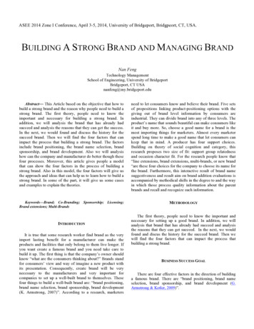
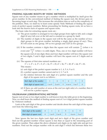
Square D Brand EX Low Voltage Distribution TransformersProduct FeaturesProduct FeaturesNew Energy Efficient Transformer Family – EXThe efficiency levels set by the U.S. Department of Energy necessitated completely new transformerdesigns. Components used within Schneider Electric transformers were optimized for performance,including: Coil—Computer designed to reduce the losses with customized wire configurations usedexclusively by Schneider Electric. Computer winding equipment to minimize variability during thewinding process. Available as standard with aluminum conductor, but also available with copper. Insulation System—The system consists of a conductor wrap or coating, layer insulation, air gapspacing, and varnish material. The system is UL listed for a specific maximum temperature foraverage temperature rise, hot spot, and ambient temperature. Schneider Electric’s EX family oftransformers have a 428 F (220 C) insulation system, with an average temperature rise maximumof 302 F (150 C). The design also allows further reduction in conductor losses, while also offeringthe product with an average temperature rise of 239 F (115 C) or 176 F (80 C).Figure 2:Insulation System Core—Transformers are designed with high grade grain oriented, non-aging silicon steellaminations with high magnetic permeability and low hysteresis and eddy current losses. Thecomputer design program allows the design to keep the magnetic flux densities well below thesaturation point. The laminations are carefully and evenly stacked in one of two coreconfigurations: distributive gap or full step mitre. Then they are clamped together to ensure themost efficient magnetic circuit while providing a quiet quality offering of low voltage transformers. Terminals—Sized to allow the lugs to align with all corresponding Schneider Electric equipment(such as: circuit breakers, switches, panels, switchboards, and so forth). Layout separates thePrimary and Secondary terminals and meet the NEC minimum bending requirements. Lugs are notshipped with the transformers to give the installer the flexibility to meet any distribution systemconductors requested. All incoming terminals are sized for 125% or 250% lug landing.NOTE: Both mechanical and compression lug kits are available from Schneider Electric.408/2016 2015–2016 Schneider ElectricAll Rights Reserved
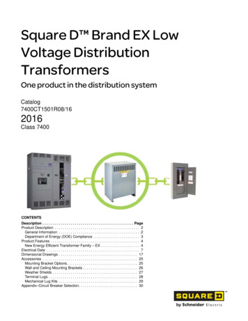
Square D Brand EX Low Voltage Distribution TransformersProduct Features Enclosure—Two new enclosure styles: K and J. See Figure 3.— Style K units are designed with no top or rear ventilation and alcove tested with ½ in.(12.7 mm)clearance from the rear and sides. The front and rear panels are designed to attach to thecover, increasing the support strength of the tops. The base is vented and designed with aconduit entry and three locations for mounting a ground terminal bar.— Style J units are designed with no rear ventilation and alcove tested at ½ in.(12.7 mm)clearance from the rear and sides. The front and rear panels are designed to attach to the covervia a u-shaped lip, increasing the support strength of the tops. The open design of theenclosure base includes three locations for mounting a ground terminal bar.Both enclosures have mounting holes on the side allowing for the use of a floor mounting kit, tomore easily bolt the unit to the floor.Figure 3: Figure 4:Style K and J EnclosureNameplate—Two nameplates are supplied with each unit (see Figure 4). One on the front coverwhich is required by standards, the second nameplate is attached to the core and coil, providinginstallation information inside the unit. The second nameplate also carries a UR listing for the coreand coil, allowing the enclosure to be removed and the device installed in other equipment.Sample NameplatesENERGY EFFICIENT LOW VOLTAGEDISTRIBUTION TRANSFORMER, DRY TYPEENERGY EFFICIENT LOW VOLTAGEDISTRIBUTION TRANSFORMER, DRY TYPEEX75T3HCAT. NO. :STYLE NO. : EAV8550503SERIAL NO. : Q2C NumberDATE CODE : 1616WEIGHT : 638LBS.75KVA :PHASE : 3FREQ. : 60 Hz% IZ :5.83TYPE : SOENCL : 20K TYPE 1, TYPE 3R WHEN 7400WS20K INSTALLEDTO BE IN ACCORDANCE WITH THE NATIONAL ELECTRIC CODE,INS CLASS : 220º CPRI ( H ) VOLTS : 480DSEC (X ) VOLTS :208Y/120PRI ( H ) AMPS : 90.2SEC (X ) AMPS : 208.2RISE : 150º CAMB :CAT. NO. :EX75T3HOCSTYLE NO. : EAV8550503SERIAL NO. : Q2C NumberDATE CODE : 161640 º CEFFICIENCY : 98.60% @ 35% LOAD & 75ºCMEETS FINAL RULE U.S. 10 CFR 431 APR 2013WEIGHT : 518ENCL : NONEKVA :75PHASE : 3FREQ. : 60 Hz5.83% IZ :LBS.TYPE : OSPRI ( H ) VOLTS : 480DSEC (X ) VOLTS :208Y/120PRI ( H ) AMPS : 90.2SEC (X ) AMPS : 208.2INS CLASS : 220 º CRISE : 150 º CAMB :40 º CEFFICIENCY : 98.60% @ 35% LOAD & 75ºCMEETS FINAL RULE U.S. 10 CFR 431 APR 2013SECTION 450.9, AND UL 1561, MAINTAIN MINIMUM CLEARANCEOF 0.5 INCH TO WALL OR OTHER OBSTRUCTIONS.TAP POSITIONSPrimaryTAPVOLTS1234567TAP 67505493480467455445433POWER TRANSFORMERPOWER TRANSFORMER127 HINS SYS. : 65 PDG220-1NOT FOR USE ON COMBUSTIBLE FLOORS127 HINS SYS :65 PDG220-1MADE IN USAMADE IN USAAttached to the Front CoverAttached to the Core and Coil5 2015–2016 Schneider ElectricAll Rights Reserved08/2016
Square D Brand EX Low Voltage Distribution TransformersProduct Features Testing—All designs are tested at state of the art test labs, UL certified, and part of the testprogram.— UL 1561 and NEMA ST-20 design and prototype testing are done on initial design— DOE product verification testing is completed yearly in compliance with 10 CFR 429— Routine testing is completed on 100% of all units shipped from the facilities.Testing is performed on all units shipped. Packaging—Shipping materials are updated to insure the new designs arrive undamaged fromhandling and logistics. Pallets are designed to increase clearances between units, and spacers areadded underneath the box to prevent small dings in the enclosure. The enclosure design is alsoenhanced to prevent damage during shipments. Quiet Quality—All units are designed and tested to sound levels 3–6 dB below the NEMA ST-20tables. Because each 3 dB cuts the audible sound in half, this new offering has the quietest units inthe marketplace. Manufacturing—All units are built in two ISO registered facilities.Product Environmental Profile:— RoHS compliant— REACH compliant— Eco-Passport608/2016 2015–2016 Schneider ElectricAll Rights Reserved
Square D Brand EX Low Voltage Distribution TransformersElectrical DataElectrical DataTable 2:kVAProduct Specifications / Catalog Numbers—Temp. Rise 150 C, Aluminum WoundPrimaryWindingDeltaFullCapacityTapsSecondary Efficiency @ 35% Temp. RiseWinding167 F / 75 C( C)Inc ClassSoundLevelCatalog No.Weight(lb.)Enclosure1598.17%39 dBEX15T3H24517K3098.38%39 dBEX30T3H40018K4598.60%39 dBEX45T3H49018K7598.69%44 dBEX75T3H71020K98.83%44 dBEX112T3H92021K47 dBEX150T3H117022K25J6–2.5% 2 4–112.5480150208Y/12099.00%15022022599.06%49 dBEX225T3H182530099.13%49 dBEX300T3H197525J50099.24%56 dBEX500T68H310030J99.34%58 dBEX750T68H412531J4–2.5% 2 2–750Table 3:kVAProduct Specifications / Catalog Numbers—Temp. Rise 150 C, Copper WoundPrimaryWindingDeltaFullCapacityTapsSecondary Efficiency @ 35% Temp. RiseWinding167 F / 75 C( C)Inc ClassSoundLevelCatalog No.WeightEnclosure(lb.)1598.10%39 dBEX15T3HCU25017K3098.48%39 dBEX30T3HCU40018K4598.57%39 dBEX45T3HCU49518K7598.70%44 dBEX75T3HCU75520K98.94%44 dBEX112T3HCU102521K112.51506–2.5% 2 4–480208Y/12015022047 dBEX150T3HCU127022K22599.04%49 dBEX225T3HCU154525J30099.12%49 dBEX300T3HCU197525J50099.32%56 dBEX500T68HCU370530J99.36%58 dBEX750T68HCU440031JWeight(lb.)Enclosure4–2.5% 2 2–750Table 4:kVA99.06%Product Specifications / Catalog Numbers—Temp. Rise 115 C, Aluminum WoundPrimaryWindingDeltaFullCapacityTapsSecondary Efficiency @ 35% Temp. RiseWinding167 F / 75 C( C)Inc ClassSoundLevelCatalog No.1598.20%39 dBEX15T3HF24517K3098.41%39 dBEX30T3HF40018K4598.62%39 dBEX45T3HF49018K7598.71%44 dBEX75T3HF92020K98.78%47 dBEX112T3HF117021K49 dBEX150T3HF182522K112.51506–2.5% 2 4–480208Y/12098.78%11522022599.08%49 dBEX225T3HF182525J30099.15%49 dBEX300T3HF197525J50099.26%56 dBEX500T68HF310030J99.35%58 dBEX750T68HF412531J7504–2.5% 2 2–7 2015–2016 Schneider ElectricAll Rights Reserved08/2016
Square D Brand EX Low Voltage Distribution TransformersElectrical DataTable 5:kVAProduct Specifications / Catalog Numbers—Temp. Rise 115 C, Copper WoundPrimaryWindingDeltaFullCapacityTapsSecondary Efficiency @ 35% Temp. RiseInc ClassWinding167 F / 75 C( C)SoundLevelCatalog No.WeightEnclosure(lb.)1598.20%39 dBEX15T3HFCU24517K3098.50%39 dBEX30T3HFCU40018K4598.60%39 dBEX45T3HFCU49018K7598.73%44 dBEX75T3HFCU92020K98.96%44 dBEX112T3HFCU117021K6–2.5% 2 4–112.5480150208Y/12011522047 dBEX150T3HFCU182522J22599.06%49 dBEX225T3HFCU182525J30099.14%49 dBEX300T3HFCU197525J50099.33%56 dBEX500T68HFCU310030J99.37%58 dBEX750T68HFCU412531JWeight(lb.)Enclosure4–2.5% 2 2–750Table 6:kVA99.01%Product Specifications / Catalog Numbers—Temp. Rise 80 C, Aluminum WoundPrimaryWindingDeltaFullCapacityTapsSecondary Efficiency @ 35% Temp. RiseWinding167 F / 75 C( C)Inc ClassSoundLevelCatalog No.1598.26%39 dBEX15T3HB40018K3098.58%39 dBEX30T3HB49018K98.73%44 dBEX45T3HB71020K98.89%44 dBEX75T3HB92021K47 dBEX112T3HB117022K45756–2.5% 2 4–112.5480208Y/12099.05%8022015099.05%49 dBEX150T3HB182525J22599.11%49 dBEX225T3HB197525J30099.15%56 dBEX300T68HB310030J99.29%58 dBEX500T68HB412531J4–2.5% 2 2–500Table 7:kVAProduct Specifications / Catalog Numbers—Temp. Rise 80 C, Copper WoundPrimaryWindingDeltaFullCapacityTapsSecondary Efficiency @ 35% Temp. RiseInc ClassWinding167 F / 75 C( C)SoundLevelCatalog No.WeightEnclosure(lb.)1598.26%39 dBEX15T3HBCU40018K3098.58%39 dBEX30T3HBCU49018K98.69%44 dBEX45T3HBCU71020K98.97%44 dBEX75T3HBCU92021K47 dBEX112T3HBCU117022K45756–2.5% 2 4–112.5480208Y/12099.03%8022015099.04%49 dBEX150T3HBCU182525J22599.12%49 dBEX225T3HBCU197525J30099.20%56 dBEX300T68HBCU310030J99.34%58 dBEX500T68HBCU412531J4–2.5% 2 2–500808/2016 2015–2016 Schneider ElectricAll Rights Reserved
Square D Brand EX Low Voltage Distribution TransformersElectrical DataFigure 5:Phase Relationships / Wiring DiagramTAPS 6 — 2.5% 2 FCAB, 4 FCBNTAPS 5-2.5% 2 FCAN, 2 FCBN9 2015–2016 Schneider ElectricAll Rights Reserved08/2016
Square D Brand EX Low Voltage Distribution TransformersElectrical DataThe transformer source impedance limits the overcurrent on the secondary terminals. Table 8 providesthe maximum amount of overcurrent available:Table 8:Technical data: IZ, IX, X/R, and Let Through Current— -H and -HCU SuffixCatalogSecondaryWindingSecondary NPCurrentSecondaryNEC 125%IZ%%IXX/RInfinite Primary BusLet .3239.1Calculation of regulation on a transformer is complex, requiring information about load power factor aswell as amperage. Since complete information is often lacking, a worse case calculation, as shownbelow, is often used to provide conservative results:Maximum load currentVoltage drop (%) x Impedance (%)Transformer secondary full load rating1008/2016 2015–2016 Schneider ElectricAll Rights Reserved
Square D Brand EX Low Voltage Distribution TransformersElectrical DataTable 9:Technical data: IZ, IX, X/R, and Let Through Current— -HF and -HFCU SuffixSecondaryWindingCatalogSecondary NPCurrentSecondaryNEC 125%IZ%%IXX/RInfinite Primary BusLet 0T68HFCU2,081.83,0005.30%5.19%4.7539.2X/RInfinite Primary BusLet ThroughkATable 10:Technical data: IZ, IX, X/R, and Let Through Current— -HB and -HBCU SuffixCatalogSecondaryWindingSecondary NPCurrentSecondaryNEC CU2,081.83,0005.30%5.19%4.3239.111 2015–2016 Schneider ElectricAll Rights Reserved08/2016
Square D Brand EX Low Voltage Distribution TransformersElectrical DataWhen voltage is applied to the input winding of a transformer there can be a brief period of inrushcurrent until the transformer core is stabilized. Inrush lasts approximately 6 power cycles, or about 0.1seconds. The magnitude of the inrush varies depending on when the switch closes on the power wave,so that inrush can be anywhere from zero to greater than the full load current rating of the transformer.In addition, the impedance of the supply system can influence the amount of inrush current thetransformer can draw. To avoid tripping breakers, or blowing fuses on the primary side of thetransformer during energizing, careful coordination of fuse sizes or breaker handle ratings andmagnetic trip settings is essential. This coordination requires information about maximum possibleinrush to be expected from the particular transformer in question.Schneider Electric has taken the inrush data for our units and plotted this data on our circuit breakers’trip curves. As a result of this data, it has been determined that circuit breakers sized at either the NEC125% or 250% levels will energize the product without tripping.Tables 19, 20, 21, 22, and 23 on pages 31-35 permits completion of the analysis by supplying themaximum inrush times rated, but also includes the type of breaker at the NEC level listed for a quickguide to choosing the proper transformer breaker.Figure 6:Primary and Secondary ProtectionThe following tables were developed by modeling the transformers in PTW softwareand plotting trip curves for each listed trip unit at the given amperage. Then, itwas verified whether or not the device could carry the full load inrush multiplier at 0.01 seconds.NOTE: Setting is the minimum instantaneous (INST) level for the sensor. For circuit breakers with tripsallowing settings, the value is shown and the sensor is in ( ).1208/2016 2015–2016 Schneider ElectricAll Rights Reserved
Square D Brand EX Low Voltage Distribution TransformersElectrical DataTransformer efficiency can be defined as the percentage of power out compared to the percentage ofpower in. A perfect zero loss transformer would have the same power in as out, and would be 100%efficient. With the implementation of EPACT2005 Final Rule 10 CFR 431 Subpart K, most low voltagetransformers exceed 98% at 35% load.For compliance with the 2005 Energy Act, manufacturers must measure and calculate the efficiencylevels using the following formula:% Efficiency 100 X P X VA(P X VA) Core Loss (P2 X Coil Loss X T)Where:P per unit load (EPACT2005 0.35)T correction factor for winding material and temperature correction (convert to 167 F [75 C])(302 F [150 C] Rise AL 0.8152; CU 0.8193)Correction factors are used because resistance losses vary by temperature and winding material.See 10 CFR 431.192 for more details on formula.Table 11:Transformer EfficiencyCoilLossTotal Loss35% / 167 F (75 C)Power In35% Load /167 F (75 C)Efficiency35% Load /167 F (75 C)Minimum EfficiencyEPACT 200510 CFR %15973.8498.60%98.40%Power Out35% Load /167 F (75 C)kVAPart 0264237.9499.34%99.23%Manufacturers are required to use sampling plans for Distribution Transformers under Department ofEnergy 10 CFR 429.47.Manufacturers can use actual test results in accordance with 10 CFR 431.193, to certify:a. Basic Modelsb. kVA GroupsManufacturers may also use Alternative Methods for Determining Efficiency for (AEDM) per 10 CFR429.70.Core loss (No-Load Loss): When a transformer is energized on the primary side, the laminated steelcore carries a magnetic field, or flux. This magnetic field causes certain losses in the core, generatingheat and dissipating real power from the primary source even when no load is on the secondary side ofthe transformer.Coil Loss (Load Loss): Under load, a transformer looses energy in the form of heat within the windingconductors. That’s because these conductors have a certain amount of resistance. Nearly all of thecoil loss can be accounted for by the simple I2R (current in amperes squared times resistance in ohms)formula for watts. There is a small amount of stray losses, and the sum of these and I2R watts equaltotal coil loss.These losses are typically reported by engineering in watts. Many contractors interested in airconditioning requirements of a building will request the BTU/HR (British Thermal Units per hour)equivalent, which can be determined as follows: BTU/HR 3.412 x Losses in Watts.13 2015–2016 Schneider ElectricAll Rights Reserved08/2016
Square D Brand EX Low Voltage Distribution TransformersElectrical DataTable 12:Transformer Core and Coil Loss–Catalog Numbers -H and -HCUWattskVACalculated Load per ST-20, 338 F (170 C)Part NumberNo Load Coil X750T68HCU78690111/6 WattsBTUs/Hr1/4 WattsBTUs/Hr1/2 WattsBTUs/Hr3/4 WattsBTUs/HrFull 41408/2016 2015–2016 Schneider ElectricAll Rights Reserved
Square D Brand EX Low Voltage Distribution TransformersElectrical DataTable 13:Transformer Core and Coil Loss–Catalog Numbers -HF and -HFCUWattskVACalculated Load per ST-20, 338 F (170 C)Part NumberNo Load Coil 0T68HFCU6674839750EX750T68HFCU78681911/6 WattsBTUs/Hr1/4 WattsBTUs/Hr1/2 WattsBTUs/Hr3/4 WattsBTUs/HrFull 10141297283374408976346044259666253853062615 2015–2016 Schneider ElectricAll Rights Reserved08/2016
Square D Brand EX Low Voltage Distribution TransformersElectrical DataTable 14:Transformer Core and Coil Loss–Catalog Numbers -HB and -HBCUWattskVACalculated Load per ST-20, 338 F (170 C)Part NumberNo Load Coil 94300EX300T68HBCU6671568500EX500T68HBCU78632761/6 WattsBTUs/Hr1/4 WattsBTUs/Hr1/2 WattsBTUs/Hr3/4 WattsBTUs/HrFull 87799016043447406129923378547311761138561608/2016 2015–2016 Schneider ElectricAll Rights Reserved
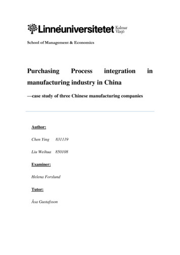
Square D Brand EX Low Voltage Distribution TransformersDimensional DrawingsDimensional DrawingsFigure 7:Enclosure 17K17.50(438)20.50(521)Approximatecenter of gravityEntering sideaccess .00(457)1.40(36)3.50(89)in.Dimensions: 85)5.36(136)Approximatecenter of gravity0.50(13)(4 Places)Entering bottomaccess pointAccessoriesWeathershield7400WS17KWall mounting bracket7400WMB17KCeiling mounting bracket7400CMB17KFloor mounting bracket7400FBMState of CA only (OSP label)7400CAOSHPDKEnclosure Parts (Replacement Parts)Top coverEAV97922Side panelEAV97912Front cover with labelsEAV97924Rear coverEAV97925Base assemblyEAV97907When ordering front cover with labels, Catalog No., Serial No., andDate Code in Engineering Notes must be supplied (see Figure 4 forlocation information on Namplate). Serial number may also beobtained from Core and Coils.17 2015–2016 Schneider ElectricAll Rights Reserved08/2016
Square D Brand EX Low Voltage Distribution TransformersDimensional DrawingsFigure 8:Enclosure 38(441)3.88(99)4.28(109)4.50(114)12.71(32
75 98.69% 44 dB EX75T3H 710 20K 112.5 98.83% 44 dB EX112T3H 920 21K 150 99.00% 47 dB EX150T3H 1170 22K 225 99.06% 49 dB EX225T3H 1825 25J 300 99.13% 49 dB EX300T3H 1975 25J 500 4–2.5% 2 2– Square D Brand EX Low Voltage Distribution Transformers . Square D