Transcription
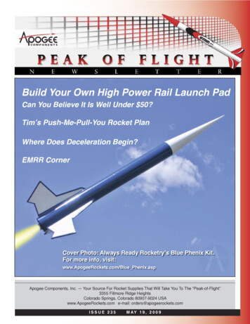
Build Your Own High Power Rail Launch PadCan You Believe It Is Well Under 50?Tim’s Push-Me-Pull-You Rocket PlanWhere Does Deceleration Begin?EMRR CornerCover Photo: Always Ready Rocketry’s Blue Phenix Kit.For more info, visit:www.ApogeeRockets.com/Blue Phenix.aspApogee Components, Inc. — Your Source For Rocket Supplies That Will Take You To The “Peak-of-Flight”3355 Fillmore Ridge HeightsColorado Springs, Colorado 80907-9024 USAwww.ApogeeRockets.com e-mail: orders@apogeerockets.comISSUE 235M AY 1 9 , 2 0 0 9
Build Your Own High Power Rail Launch PadBy Daniel Kirk{Edtor’s Note: In the last newsletter, I disclosed asecret list of ten types of products that I thought would begreat selling items (see er234.pdf). One of those items onthe list was a rail launcher for mid and high power rockets.In response to that article, Daniel Kirk of Union Grove, Wisconsin wrote me about his really cool rail launcher that hebuilt for a really cheap price using PVC pipe he bought atthe hardware store. Excluding the rail, the total cost of thelaunch pad was under ten dollars!}joint against rotational forces.Mast Construction1. Mark a longitudinal line on one length of PVC. (ASharpie marker is good for this.) Drill pilot holes on the line,and screw in rail buttons. One at each end would probablydo, but I used 4 buttons, one an inch from each end, andanother 3 inches from each end. Leave the bottom plasticwasher off the rail button for a tighter fit.Parts ListA) 1-1/4” PVC pipe 5 pieces, 3 ft ea. (I’d have to checkthe price on this again.)B) 1-1/4” PVC Tees, Slip-fit 3 @ .99 ea.C) 4” electrical junction box cover, 1 @ .55 eaD) Rail Buttons 6 @ .25 ea.E) 1 Wood screwF) 4 small machine screwsG) 7” of scrap 2 x 4 (dimension not critical)H) Rail (http://www.8020.net/): 22 plus shippingLeg ConstructionCut PVC to length with a hand saw.Base Construction1. Cut two pieces from the scrap PVC just long enoughto join the tees.2. Join two teesend-to-end with PVCcement, rotating them sothe middle leg of each teeis at a right angle to theother. When dry, add thethird tee with its middleleg at 90 degrees to thatof the center tee, and 180degrees to that of the teeat the opposite end.Bracket for Blast Deflector Construction3. When dry, drill ahole for a machine screwon either side of each joint. Insert screws to strengthen theAbout this Newsletter1.Cut one end of the 2 x 4 scrap at a 45 degree angle.Install two rail buttons onthe long side, one nearthe top, and the other3-4” below it, again omitting the bottom washer.Drill a pilot hole, andscrew the wood screwinto the angled surfaceFigure 3: Blast deflectornear the top.bracket with rail buttons.Continued on page 3Newsletter StaffYou can subscribe to receive this e-zine FREE at the ApogeeComponents web site (www.ApogeeRockets.com), or bysending an e-mail to: ezine@apogeeRockets.com with “SUBSCRIBE” as the subject line of the message.Page 2Figure 2: Base of the launcher. (A) Screws in additionto the glue to provide extra support to keep the mastpole from rotating. (B) Mast pole. (C) Rail buttons tohold rail to the mast pole.ISSUE 235Writer: Tim Van MilliganLayout / Cover Artist: Tim Van MilliganProofreader: Michelle MasonM AY 1 9 , 2 0 0 9
Continued from page 2Build A Rail Launch Pad5. Hang the deflector on the wood screw.On-Field Assembly (see photos)Generalized notes about the design:1. Slip a 3 ft leg into each of the four available openingsin the base piece.The hard part of building most rail pads is attachingthe rail to the pad. Basically most designs adapt the rail toa rod, then mount the rod to the pad. Using rail buttons issimpler, faster and cheaper.2. The leg with the rail buttons is the mast pole. Standit in the vertical leg of the center tee, and press down for asnug fit.3. Slide the rail onto the buttons on the mast.4. Slide the blast deflector bracket onto the rail.PVC pipe is inexpensive, but most pad designs thatuse it use expensive and hard-to-find connectors. Anyfitting more complex than a tee is expensive. Multiply thenumber of openings by the diameter of the pipe to get therelative cost.The 3-Tee base breaks down smaller than other bases(crosses, corners, and H’s) so it fits in a canvas bag withthe legs, without sacrificing strength or stability.One way I saved weight and cost was not making therail angle adjustable. If my rocket needs a rail, I want it going straight up. If you need to launch into the wind, it’s toowindy for big rockets.The other reason most big pads tilt is to load the rocketon the rail. With the top of my rail only 6 ft from the ground,I can easily reach it. If the rocket is awkward to raise overmy head, I can lift the mast out of the base, tilt it over, loadthe rocket, and replace the mast.Figure 4: The blast deflector (metal outlet cover) is attached to the bracket with a wood screw. The bracketis then slid down the rail itself and rests on the ground.Most mid and high power pads raise the rocket offthe ground. This adds cost and complexity, and sacrificesstability. In other words, you need longer legs or stakes inContinued on page 4Model Rocket Design and ConstructionBy Timothy S. Van MilliganNew 3rd Edition Now Shipping!This new 328 page guidebook for serious rocket designers contains themost up-to-date information on creating unique and exciting models that really work. With 566 illustrations and 175 photos, it is the ultimate resourceif you want to make rockets that will push the edge of the performanceenvelope. Because of the number of pictures, it is also a great gift to giveto beginners to start them on their rocketry future.For more information, and to order this hefty book, visit the Apogee website at: www.ApogeeRockets.com/design book.aspApogee Components3355 Fillmore Ridge HeightsColorado Springs, Colorado 80907 USAtelephone: 719-535-9335website: www.ApogeeRockets.comISSUE 235M AY 1 9 , 2 0 0 9Page 3
Continued from page 3Build A Rail Launch Padthe ground to keep your pad from tipping over in a gust ofwind. It also makes it harder to load the rocket on the pad.The main advantage of raising the pad is that you don’tContinued on page 5Figure 5-7: The pad breaks down into components, andis easly transported in a folding chair bag (left). Thepad when fully assembled (above) .Let’s Cluster Some MotorsClustering: A boost technique which uses 2 or more motors side by side in the same rocket. Safe operation of rocketswith different motor thrusts, in a cluster would be to ensure symetrical thrust around the center vertical axis of the rocket.This is also sometimes accomplished by canting motors toward the center of gravity.Cluster Ignition Tip - check thecontinuity of each igniter AFTER pluginstallation but BEFORE you twistthem all together.Fliskits has a very popularand unique way to get intoclusters with the excitingDeuce’s Wild Kit.Boris Katan and his CLUSTER TOGinator.What started as a 1.6xupscale of the FlisKits USTOG. turned into something more! Flies on 3x “G”Redline, 12x “E9” and 12x“D11” motorsThere may be copies ofthe idea and design outthere, but the Deuce ishere to stay!Brought to you by Essence’s Model Rocketry Reviews & Resourses - www.rocketreviews.comPage 4ISSUE 235M AY 1 9 , 2 0 0 9
Continued from page 4Build A Rail Launch Padhave to kneel on ground that may be rocky or wet. Solution:I bought a foam kneeling pad made for gardeners. The deluxe model is 4.50 at Wal-Mart. If the ground is really wet,I lay a plastic garbage bag on the ground under it.I fly mostly mid-power. My HPR are toward the smallerend of the scale. For larger rockets, the design could bescaled up with larger diameter pipe, longer legs, longer rail,etc. In that case, I’d add screws as added insurance thatthe mast and legs couldn’t wiggle.About the Author:Dollar for dollar, you’ll see the most results by advertising in the Peakof-Flight Newsletter. In fact, I guarantee it. If you don’t see more resultsfrom your advertisement in the Peak-of-Flight Newsletter, I’ll run youradvertisment for two more issues at NO COST!Call us at: (719) 535-9335Daniel Kirk writes: “I flew rockets as a kid in the early‘80s. Even saved enough money from collecting cans anddoing odd jobs to go to Space Camp. In 1999, I met BobWingate, who introduced me to his club, KCAR #505. Iwas amazed at the developments since I’d left the hobbyin the mid-80’s, and found it was even more fun to fly witha group. I flew with KCAR and also with SMART #644 untilI moved to Wisconsin, where I fly with WOOSH #558. Iserved as president of KCAR for 2 years.I enjoy designing, building, and flying rockets, andam always looking for new ideas and ways to improve myskills, so I especially enjoy the wealth of information available from Apogee Components.” Won’t Shatter Like Brittle Phenolic Tubes! Super Smooth Surface With Tight Spirals Standard LOC Diameters Up To 6 inches Cut and Slot With Standard Tools No Fiberglass Wrap Needed Sands and Paints Easily Cheaper than FiberglassBlue Tube FromAlways ReadyRocketrywww.ApogeeRockets.comHigh Power Tubes & Couplerswww.ApogeeRockets.com/blue tubes.aspISSUE 235M AY 1 9 , 2 0 0 9Page 5
Where Does Deceleration Start?By Tim Van MilliganI got a question this past week from a RockSim user.The situation was that he was using Aerotech’s ElectronicForward Closure in his rocket, and wanted to know how toset it up in RockSim. That is what I’ll try to explain in thisshort article.First of all, we don’t currently carry the Aerotech Electronic Forward Closure, but we can special order it for you ifyou want it. Just give us a call at (719) 535-9335.The device is an electronic timer that attaches to theforward end of the Rouse-Tech motor cases (www.apogeerockets.com/Rouse-Tech Monster Motors.asp). Itsimply replaces the regular forward closure piece on themotor. The purpose of the device is to eject the parachuteout of the rocket. Why use it? Many of the bigger motorsdo not have built-in ejection charges because the case isplugged. And many rocketeers like to get rid of the built-inpyrotechnic delay because they may not be very accurate ifimproperly assembled. So going to an electronic device canbe more accurate. Finally, it can be used for extra redundancy in the situation where you are using other electronicdevices to control the ejection of the chute.How does the Electronic Forward Closure differ fromother timers, such as the Perfect Flight MiniTimer3 (www.Figure 1: Aerotech’s Electronic Forward Closureapogeerockets.com/Staging Timer.asp)? After all, a timer isa timer; they just count the number of seconds and then fireoff an igniter to start an event (an “event” is either ignitinganother stage in the rocket, or firing off the ejection chargeto deploy a parachute).The obvious physical difference is that the ElectronicForward Closure attaches to the rocket motor, where theMiniTimer3 must be mounted elsewhere in the rocket.But the key difference is how the devices start. Mostelectronic timers, such as the MiniTimer3, start by sensing lift-off. The MiniTimer has a G-sensor that detects theContinued on page 7 Designed to ignite the topmotor in two-stage rockets. Provides an easy way tostage composite propellant motors Fires off igniters after apreprogrammed amount oftime following liftoff G-switch senses liftoff andinsures against a false launchdetection Small, lightweight design is greatfor skinny rockets Easy-to-use, and will fire off any igniter, including clusters!Battery, battery connector, mountingboard and igniter are not incuded.Page 6www.ApogeeRockets.com/Staging Timer.aspISSUE 235M AY 1 9 , 2 0 0 9www.ApogeeRockets.comStaging Electronics
Continued from page 6Where Does Deceleration Start?acceleration of the rocket as it starts to move up the launchrod. This makes it easy to set up simulations in RockSim.For example, say you wanted to use the timer to deploy adrogue chute at Apogee. You simple set the timer to thenumber displayed in the column “Time to Apogee.”That’s it,and you’re done.The Aerotech Electronic Forward Closure senses therocket decleration (where it begins to slow down). At firstglance, you would assume that you’d use the “OptmumDelay” value in RockSim to set the timer. After all, if the deceleration begins at burnout, then the optimum delay wouldbe the correct number.For most situations, this is good enough, and that iswhat I’d recommend that you do. Just look at the summaryscreen in RockSim and use the Optimum Delay value to setthe timer.But if you wanted more accuracy, then you’d have tolook at the graphs in RockSim to find out where deceleration actually begins. Why?The assumption is that deceleration begins at motorburnout. It is usually close, but if you study the graphs,you’ll see that the rocket actually decelerates (where acceleration becomes a negative number) prior to motor burnout.In Figure 2, you can see a comparison of the acceleration and the thrust curves for the Always-Ready-RocketryBlue Phenix kit using an H123W motor. Note: I use theY-Acceleration data instead of just “Acceleration” becauseit is easy to see deceleration – since the number goes to anegative value.The blue line on the graph is the thrust of the motor.You can see it burns out at 2.6 seconds. The accelerationcurve goes negative prior to that. While it depends on whatFigure 2: Comparison of where deceleration startsbased on drag coefficient. Example rocket was a BluePhenix kit, simmed with H123W motor.drag coefficient you use, it will always be prior to engineburnout.How soon will it be? Well, deceleration occurs whenthe thrust force produced by the motor is less than the sumof the drag and the gravity forces acting on the rocket. Inother words, the higher the drag and the heavier the rocket,the sooner it will begin to decelerate. That is why the curvein Figure 2 for the rocket with the Cd value of 0.9 occurssooner than the rocket with a Cd value of 0.4 (2.22 secondsversus 2.36 seconds).Remember too that the thrust of the motor also playsa role in this too. If you have a long burn motor, the thrustat the end of the burn tails off gradually, so that is going topush the deceleration point further forward.What does all this mean to us? Well, if we need toset the timer to eject right at apogee, we might be off by aContinued on page 8Your Cool Rocket DesignsLook So Much Better InRockSim Version 9!Launch It.v9www.RockSim.comSpace Foundation certifiedas an excellent teaching aid.For further information, call Apogee Components at: 719-535-9335.ISSUE 235M AY 1 9 , 2 0 0 9Page 7
Continued from page 7Where Does Deceleration Start?significant amount of time. In this example, if you read offthe graph that decleration begins at 2.22 seconds when themotor burnout is 2.6 seconds, your timer would be off by.38 seconds if you used the Optimal Delay from the summary screen in RockSim.Now 0.38 seconds really isn’t a long time in most rockets. But you get the idea. You’ll need to check your simulations to see if that is going to result in a situation wherethe rocket is still travelling at a high rate of speed when thedrouge chute is ejected.So the procedure to set the correct delay value forAerotech’s Electronic Forward Closure is to look at theaccleration curve graph and find out when it begins deceleration. Take that number and subtract it from the total burntime of the motor. This will give you how much time beforeburnout the rocket decelerates (and where the timer willstart timing). Now take this number and add it to the Optimal Delay values. The final value is the number you’d useto set the Electronic Forward Closure timer to eject right atapogee.It isn’t hard, is it?is very valuable in this situation, as it can save you fromsetting up your electronics incorrectly. That’s one reasonwhy I use it. Do you?About The Author:Tim Van Milligan (a.k.a. “Mr. Rocket”) is a real rocketscientist who likes helping out other rocketeers. Before hestarted writing articles and books about rocketry, he workedon the Delta II rocket that launched satellites into orbit. Hehas a B.S. in Aeronautical Engineering from Embry-RiddleAeronautical University in Daytona Beach, Florida, andhas worked toward a M.S. in Space Technology from theFlorida Institute of Technology in Melbourne, Florida. Currently, he is the owner of Apogee Components (http://www.apogeerockets.com) and the curator of the rocketry education web site: http://www.apogeerockets.com/education/.He is also the author of the books: “Model Rocket Designand Construction,” “69 Simple Science Fair Projects withModel Rockets: Aeronautics” and publisher of a FREE ezine newsletter about model rockets. You can subscribe tothe e-zine at the Apogee Components web site or by sending an e-mail to: ezine@apogeerockets.com with “SUBSCRIBE” as the subject line of the message.This is a great exercise to learn a bit more about thrust,drag and gravity. It is fun to play with and see what therocket may do in a lot of situations as everything changeswhen your rocket doesn’t go perfectly straight up. RockSimYes.We Have EngineMounts Too.You get:(4) AT 29/13(4) AT 41/18(2) AT 56/18(2) AT 66/18(1) AC-56(1) AC-66Price: 22.72You Save: 5.17www.apogeerockets.com/motor mount kits.aspFREE RocketConstructionVideosYou get:(6) AT 13/18(6) AT 18/18(6) AT 24/18(6) AT 33/18A new Apogeevideo every twoweeks to help youbecome a bettermodeler!www.ApogeeRockets.com/Rocketry Video tips.aspPage 8ISSUE 235Price: 26.00From Estes, you wouldspend over 44.45!http://www.ApogeeRockets.com/body tubes.aspM AY 1 9 , 2 0 0 9
Rocket Plan: Tim’s Push-Me Pull-YouBy Tim Van MilliganOn page 260 of Model Rocket Design and Construction, I showed a picture of a model I built for the NAR’scompetition event called “Four A-motors, Cluster Altitude.”As you might expect, the purpose of the event is to flythe highest possible using four A motors. I never flew therocket, but I have seen similar designs used in competition,and they worked fine.A reader of this newsletter, Tsolo Tsolo, asked me if itwas possible to simulate this design in RockSim. That gotme scratching my head, because I wasn’t sure if it was possible. I knew it wouldn’t be possible in the old version 8, butI told Tsolo that I suspected that it would be in version 9.0.Well, I had to make sure because my integrity was onthe line. Having a few minutes of free time this morning, Isat down and put it into RockSim version 9. It does work!The design is pretty complicated in version 9, as it hasa total of seven external pods, four nose cones, and eachof the four fins must be attached seperately. I input theparts the same way that I would have physically built it. Butevery time I added a part, I first had to add a pod. And eventhough I used cut-and-paste extensively throughout theprocess, I still had to revisit every part to make sure that itwas positioned and oriented properly.Figure 1: A 3D RockSim (version 9) image of the PushMe Pull-You rocket.If you would like to see how this rocket is assembledin RockSim v9, you can download the design file at: www.ApogeeRockets.com/Education/Downloads/Push-Me PullYou.rkt.zip.This rocket configuration has a lot of cool features.I wish I could say that I could take credit for the tractorengine (the motors up on top), but that goes to quite a fewContinued on page 10 Reusable Rocket Motors Save Money Holds Aerotech’s Reload Propellant Sizes: 24mm To 98mm Diameter Power Range: E Through N Cases For Any Project Rouse-Tech Quality Affordable!www.ApogeeRockets.comHigh-Power Reload Casingswww.ApogeeRockets.com/Rouse-Tech Monster Motors.aspISSUE 235M AY 1 9 , 2 0 0 9Page 9
Continued from page 9Rocket Plan: Tim’s Push-Me Pull-Youmodelers that have done it before my time.By using the tractor motors in the front, the diameterof the rocket is reduced and therefore the drag is reduced.That allows the rocket to fly higher than an arrangementwhere all the four motors were clustered at the rear of themodel. In addition to that, the tractor motors also shift theCG of the rocket forward making the model more stable.Plus, the two motors on top control two differentstreamers for recovery. That gives some redundancy to therocket in case one motor in the top does not ignite properly.According to RockSim, this rocket can reach 1,600 feet(487.7m) on four A3-4T motors. It could go higher if therewas a longer available delay. If such an motor actually existed, the rocket could top out at 2028 feet (618.1m). If youdid a delayed ignition on the tractor motors, so that theylit a little later in the flight, the rocket can go even higher.Pretty cool, eh?The one drawback is that the exhaust of the tractormotors are going to impinge on the lower nose cones.Because of that, I’d recommend they be solid balsawood,and coated with epoxy to give them some heat resistence.It is going to get pretty sooty between flights, but the effectis going to be pretty cool when you launch it.Don’t you think that RockSim v9 is very cool to allowsuch a configuration? Imagine what creative things youcould design using it.Tim's Push-me Pull-YouLength: 22.6550 In. , Diameter: 0.5440 In. , Span diameter: 5.1337 In.Mass 54.277 g , Selected stage mass 54.277 gCG: 13.6153 In., CP: 19.8343 In., Margin: 11.45 OverstableEngines: [A3T-4, A3T-4, A3T-4, A3T-4, ](S)(S)(M)(M)TMNOW ON SALE -Available Online &Worldwide throughQuality Hobby Shops& Online Retailers25% off selected model rocket kits - available from Apogee Rockets and Sunward!25 NOW ON SALE % off Nylon Parachutes, NOMEX Flame Resistant Blanketsand Shock Cord Protectorsavailable from Sunward - www.sunward1.comNEW 24” x 24”NOMEX Flame Resistant Blankets and5 foot x foot NOMEX Flame Resistant Ground Cover BlanketsSALE EXTENDED UNTIL MAY 31. GREAT SAVINGS NOWwww.sunward1.com info@sunward1.comTMDirect 416-953-1847 fax 416-245-7985Page 10ISSUE 235M AY 1 9 , 2 0 0 9TM
Mast Construction 1. Mark a longitudinal line on one length of PVC. (A Sharpie marker is good for this.) Drill pilot holes on the line, and screw in rail buttons. One at each end would probably do, but I used 4 buttons, one an inch from each end, and another 3 inches from each end. Leav