Transcription
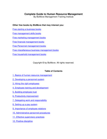
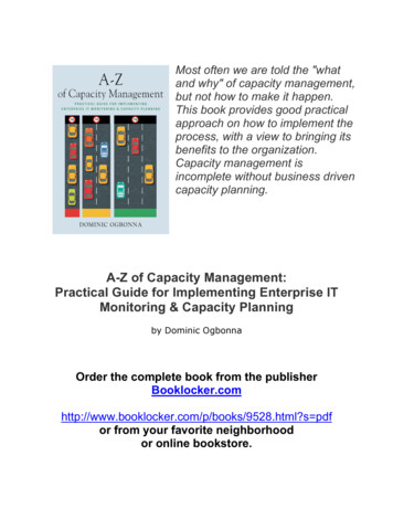
Issue date:14th June 2012FREE-ENERGY:NIKOLA TESLA SECRETS FOR EVERYBODYby Vladimir Utkin u.v@bk.ruFIRST SECRETAll of Tesla’s secrets are based onELECTROMAGNETIC FEEDBACKEXPLANATION: An ordinary energy system comprises a generator and motor (common view), and can becompleted with an electric current feedback as shown here in electrical circuit (a)NO FREE-ENERGYFREE ENERGY IS POSSIBLE(a)(b)Electrical feedbackElectroMagnetic field feedbackIn case (a), the system once started, will slow down and stop because of friction, resistance and so on. NikolaTesla arranged a feedback loop for the electromagnetic field: case (b), and he said:ELECTROMAGNETIC FIELD FEEDBACK DESTROYS THE INTERACTION SYMMETRYThis means that an action no longer has an equal and opposite reactionIn case (b), once started, the system will accelerate in spite of friction, resistance and so on (provided that thephase of the electromagnetic feedback is positive and is sufficiently large). In order for an electromagnetic field toexist in a motor, there must be some energy input, and Tesla said:ENERGY GENERATION BY IT’S OWN APPLICATIONQUESTION: How can you produce positive electromagnetic field feedback?AN ANSWER: The simplest and well-known example is Michael Faraday’s unipolar motor, as modified byNikola Tesla:(a)(b)1
An ordinary unipolar motor consists of a magnetised disk, and a voltage applied between the axis and a point onthe circumference of the disc as shown in (a) above. But an ordinary unipolar motor can also consists of anexternal magnet and a metal disc with a voltage applied between the axis and a peripheral point on the disc as in(b) above. Tesla decided to modify this version of the unipolar motor. He cut the metal disc into helical sectionsas shown here:In this case, the consumption of current produces an additional magnetic field along the axis of the disc. Whenthe current-carrying wires are tilted in one direction, their magnetic field augments the main external magneticfield. When the wires are tilted in the other direction, their magnetic field reduces the main external magneticfield. So, the current flow can increase or reduce the external magnetic field of the unipolar motor.Amplification is not possible without applying powerIf it is possible to arrange a magnetic field feedback loop for mechanical devices, then it is probably possible toarrange it for solid-state devices like coils and capacitors.The others parts of this article are devoted to devices which use coils and capacitors. All of the examples in thisarticle are only intended to help your understanding of the principles involved. Understanding would be madeeasier if we pay attention to the ferromagnetic shielding of the second coil in the transformer invented by NikolaTesla:In this case, the ferromagnetic shield separates the first and second coils in the transformer from each other, andthat shield can be used as magnetic field feedback loop. This fact will be useful for understanding the final part ofthis article. It is also helpful to consider the properties of the electrostatic field.ELECTROSTATICS(scalar field and the longitudinal electromagnetic waves)Comment: Mr. Tesla said, “there is radiant energy, perpendicular to the surface of any charged conductor,produced by a scalar electromagnetic field, thus giving rise to longitudinal electromagnetic waves”.At first glance, this contradicts the age-old experience in studying the electromagnetic field (according to modernconcepts, any electromagnetic field has components which are perpendicular to the direction of the propagated2
electromagnetic wave), also, Maxwell's equations describe an electromagnetic field as a vector. However, the firstimpression is erroneous, and no contradiction exists.Definitions of Physics: Any conductor has both inductance and capacitance, that is, the ability to accumulatecharge on it’s surface. A charge on the surface of a conductor creates an electric field (electrostatic field). Thepotential (voltage) at any point of the electric field is a scalar quantity!!! (That is, it is a scalar electric field .).If the electric charge of the conductor varies with time, then the electrostatic field will also vary with time, resultingin the appearance of the magnetic field component:Thus, the electromagnetic wave is formed (with the longitudinal component of E .).REMARK: In order to understand how a longitudinal wave interacts with conductive bodies, one needs to readthe section of electrostatics entitled "Electrification by Influence". Particularly interesting are Maxwell's equationswhere they mention the displacement current.Now we come to the first secret:3
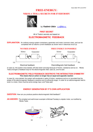
SECRET 1The power source in Nikola Tesla’s free energy device, the amplifying transformer, is aSELF-POWERED L-C CIRCUITEXPLANATIONSAN EXAMPLE OF UNLIMITED VOLTAGE RISE(Based on batteries and a switch)EXPLANATION: Batteries 1 and 2 are connected to the capacitor C alternately, through the inductances L.Voltage on capacitor C and the voltage from the batteries are increasing. As a result, there can be unlimitedvoltage rise. When the voltage on the capacitor reaches the desired level, it is connected to the load.COMMENT: Two diodes were used to avoid synchronisation requirements. Manual or relay switching can beused. One implementation used a spark gap to connect the output load but a switch is an alternative method.4
TIME LINE FOR THE PROCESS:The schematics can be simplified, and only one battery used (load is connected in the same way).COMMENT: Maybe Alfred Hubbard used an idea shown as option B, in some versions of his transformerCOMMENT: If you want to get a self-powered circuit, you have to arrange some kind of energy feedback to thebatteries. But, is this an actual Free-Energy technology? I am not sure .COMMENT: Is this the only possible way?No, of course not - there are different ways of doing it. For example, you can use fields inside andoutside of some LC circuits. How can we do that?For more secrets read the following parts 5
HOW DO WE GET THIS RESULT?AN ANSWERYou need to charge the capacitor using the electric component of the electromagnetic field of the inductor (usingthe displacement current of Maxwell’s equations)EXPLANATIONWhen the electric field in capacitor C is decaying, due to feeding electrical current into an inductor (not shown),the external electric field generated by the inductor tries to charge this capacitor with the inductor’s displacementcurrent. As a result, the capacitor draws energy in from the surrounding electromagnetic field, and the capacitor’svoltage rises cycle by cycle.IMPLEMENTATION A – a central capacitor is used:6
IMPLEMENTATION B – no capacitors are used:In this case instead of using a capacitor, the capacitance between the two sections of inductor L provides thenecessary capacitance.HOW DO WE START THE PROCESS?In implementation A, you must charge the capacitor and connect it to the inductor to start the process.In implementation B, you must use an additional pulsing or “kicking” coil, which starts the process by providing apulse in either the electrical field or the magnetic field (shown later on).HOW DO WE STOP THE PROCESS?The process of pumping energy can continue uninterrupted for an unlimited length of time and so the questionarises; how do you stop the device if you should want to?. This can be done by connecting a spark gap acrossthe coil L and the resulting sparking will be sufficient to stop the process.THE “KICKING” PROCESS USING AN ELECTRIC FIELDUse an additional special “kicking” coil, which can generate short powerful magnetic pulses, and install anamplifying Tesla coil along the electrical vector of the electromagnetic field of this coil.7
The electrical field of the driving pulse or “kicking” coil will charge the spread capacitors of the inductor, and theprocess will be started. Use pulses as short as possible in “kicking” coil, because the displacement currentdepends on the speed of the changes in the magnetic field.THE “KICKING” PROCESS WITH A MAGNETIC FIELDIt is not possible to “kick” the process by displacement of the amplifying Tesla coil in the uniform changingmagnetic field of the “kicking” coil, because the output voltage on the ends of the Tesla amplifying coil will beequal to zero in this case. So, you must use a non-uniform magnetic field. For that you must install a “kicking”coil, not in the centre of the amplifying Tesla coil, but positioned away from the centreIS THAT ALL TRUE, AND THE BEST TECHNIQUE TO USE?No, it is not! Nikola Tesla found more subtle and more powerful method – his bi-filar pancake coil!8
BI-FILAR PANCAKE COIL – MAY BE THE BEST METHODThe voltage between adjacent turns in an ordinary coil is very low, and so their ability to generate additionalenergy is not good. Consequently, you need to raise the voltage between adjacent turns in an inductor.Method: divide the inductor into separate parts, and position the turns of the first part in between the turns of thesecond part, and then connect end of the first coil to the beginning of the second coil. When you do that, thevoltage between adjacent turns will be the same as the voltage between the ends of the whole coil !!!Next step – rearrange the position of the magnetic and electric fields in the way needed for applying amplifyingenergy (as described above). The method for doing this is – the flat pancake coil where the magnetic andelectric fields are arranged in exactly the way needed for amplifying energy.Now, it is clear why Tesla always said that his bi-filar pancake coil was an energyamplifying coil !!!REMARK: for the best charging of the natural self-capacitance of the coil, you have to use electric pulses whichare as short as possible, because the displacement current as shown in Maxwell’s equation, depends to a majordegree on the speed of the change in the magnetic field.THE DUAL - LAYER CYLINDRICAL BI-FILAR COILInstead of the standard side-by-side cylindrical bi-filar coil, the coil winding may also be arranged in two separatelayers, one on top of the other:9
THE ELECTRO – RADIANT EFFECT(Inductance in an electrostatic field)EXPLANATIONThe primary coil in Tesla’s transformer is thefirst plate of the capacitor. The secondary coil - isthe second plate of the capacitor.When you charge a capacitor C from your sourceof energy, you charge a wire of the primary coilalso. As a result, a wire of the secondary coil ischarging also (as a return from ambient space).In order to start the process, you have to removecharge from the primary coil (by arranging a jumpin potential in ambient space). When this is done,a huge displacement current occurs – as a result ofthat potential jump. Inductance catches thismagnetic flux, and you have energy amplification.If this process is operating, then you generate amagnetic field in ambient space.COMMENT: The capacitance of the wire of theprimary coil is very low, and so it takes very littleenergy to charge it, and a very short spark todischarge it (without removing charge from thecapacitor C).COMMENT: Notice that the spark gap must be connected tothe ground as, in my opinion, this is a very important feature of this process, but Mr Tesla did not showgrounding. Perhaps this needs to be a separate grounding point.REMARK: In my opinion, this technology was also used in Gray’s device and in Smith’s devices and in bothcases the spark gap was connected to the ground.ALSO:Pay attention to the words used in Gray’s patent “ . for inductive load”.And, pay attention to Smith’s words “I can see this magnetic field, if I use a magnetometer”.10
MODERN IMPLEMENTATIONSin self-powered L-C circuitsEXAMPLE 1Using a bi-filar coil as the primary coil in a resonant Tesla transformerBy Don SmithExplanation: The bi-filar primary coil is used as primary for energy amplification, and is pulsed through the sparkgap.11
EXAMPLE 2By MislavskijIs comprised of two capacitor plates sandwiching a ferrite ring core with a coil wound on it:EXPLANATIONWhen a capacitor is charging (or discharging), this “displacement” current flow generates a magnetic field in thevacuum in a circular form (Maxwell’s equations). If a coil is wound on a ferrite toroid placed between the plates ofthe capacitor, then a voltage is generated in the turns of that coil:Also, if an alternating current is applied to the coil wound on the ferrite toroid,then voltage is generated on the capacitor plates.If an inductor and a capacitor are combined in an L-C circuit, then there aretwo cases inside such an L-C circuit:a) energy amplification and b) energy destructionThe situation depends on how the coils and capacitor are connected togetherEnergy GenerationEnergy DestructionCOMMENT: If the direction of the turns in the coil wound on the ferrite core is reversed,then the wires connecting the coil to the capacitor plates need to be swapped over aswell.The first experiments with a ferrite core inside a capacitor were made in 1992 by Mislavskij (a 7th-year pupil of theMoscow school), and so it is known as “Mislavskij’s transformer”.PROTOTYPE TRANSFORMER:12
THE SAME APPROACH?By Don SmithIn this arrangement, the capacitor is charged by sparks and powerful displacement current is produced. Thetransformer with the ferromagnetic core is collecting this current.COMMENT: This schematic diagram is very rough, and lacking in details. It will not perform correctly withoutback-electromagnetic force suppression of some kind (see below).13
SECRET 1.1Back-EMF suppression in a resonating Tesla coilVersion 1The primary and secondary coils, and the ground connection in this Tesla coil are arranged in special manner:Explanation: The exciting (driving) current and the load current in an electromagnetic field, are perpendicularto each other as shown here:COMMENT: In order to get an energy gain, the frequency of excitation of the primary coil must be the resonantfrequency of the secondary coil.COMMENT: Excitation with just a single spark is possible.COMMENT: In Mr. Tesla’s terminology, this is pumping charges or charge funneling, the charge is coming fromthe ground (which is a source of energy).14
POTENTIAL (VOLTAGE) DISTRIBUTION ON THE COILEXPLANATION The task of the oscillating circuit is to create a local electromagnetic field with a large electricalcomponent. In theory, it would only be necessary to charge up the high voltage capacitor just once and then alossless circuit would maintain the oscillations indefinitely without needing any further power input. In reality,there are some losses and so some additional power input is needed.THESE OSCILLATIONS ACT AS A "BAIT", ATTRACTING CHARGE INFLOW FROM THE LOCALENVIRONMENT. Almost no energy is needed in order to create and maintain such a "bait".The next step is to move to this "bait" to one side of the circuit, close to the source of the charges which is theGround. At this small separation, breakdown occurs and the inherent parasitic capacitance of the circuit will beinstantly recharged with energy flowing into the circuit from outside.At the ends of the circuit there will be a voltage difference, and so there will be spurious oscillations. The directionof this electromagnetic field is perpendicular to the original field of the "bait" and so it does not destroy it. Thiseffect is due to the fact that the coil consists of two opposing halves. The parasitic oscillations gradually die out,and they do not destroy the “bait” field.The process is repeated spark by spark for every spark which occurs. Consequently, the more often sparksoccur, the greater the efficiency of the process will be. The energy in the "bait" experiences almost no dissipation,providing a much greater power output than the power needed to keep the device operating.15
TESLA SCHEMATICSCOMMENT: Don Smith named this technology “Bird on the wire”. The bird is safe on the wire until a sparkoccurs.COMMENT: Mr. Tesla named this technology a “charge funnel” or “charge pump”THE PRINCIPLE OF THE TECHNOLOGY1. This Free-Energy device generates an AC electrical potential in ambient space (“bait” for electrons),2. Electrons flowing through the load, flow in from the environment, attracted by this “bait” (pumped in)NOT A SINGLE ELECTRON USED FOR EXCITING AMBIENT SPACE NEEDS TO FLOW THROUGHTHE LOAD16
POSSIBLE DESIGN FOR THE “CHARGE PUMP” OR “CHARGE FUNNEL”By Edwin GrayProbable Schematic for Edwin Gray’s Cold Electricity CircuitEXPLANATION: This schematic is a simplification of Gray’s patent, produced by Dr. Peter Lindemann forgreater clarification in his book.17
POSSIBLE DESIGN FOR THE “CHARGE PUMP” or “CHARGE FUNNEL”EXPLANATION: The charging system is unable to “see” the field inside a charging capacitor.COMMON VIEW OF RESONANCE: Resonance is not destroyed if you short-circuit or open a “pumping”capacitor.COMMENT: You can add an ordinary, very large capacitor in parallel with the “pumping” capacitor for moreimpressive results.Don Smith illustrationCOMMENTS: You have to use an alternating E-field, in order to charge the capacitor. But, Smith marked theNorth and South poles in his drawing. I think that this is true for only one instant. Diodes are not shown in hisdrawings, which indicates that his device as shown, is to my mind not complete.18
THE EXTERNAL APPEARANCE OF ED GRAY’S TUBEEXPLANATION: Gray’s tube with it’s two internal grids is seen in the middle. Two diodes are underneath theacrylic sheet (?). A Leiden Jar is located on the left (?) The HF HV coil is behind Gray’s tube (?)A POSSIBLE DESIGN FOR THE “CHARGE PUMP” or “CHARGE FUNNEL”THE TESTATIKA by Paul BaumanEXPLANATION: The central electrode in the jars (capacitors) is for the excitation of ambient space; the twoexternal cylinders are the plates of the charging capacitors.EXPLANATION: The charging mechanism is unable to “see” the field inside the charging capacitors.COMMENT: For more details read the section on asymmetrical capacitors.19
A POSSIBLE DESIGN FOR THE “CHARGE PUMP” or “CHARGE FUNNEL”COMMENT: This is based on Tesla’s schematicsCOMMENT: First, you need to arrange a “voltage killer” barrier on one side of the Tesla coil. This is to create a“BLIND” charging system which can’t “see” the charge on the capacitor (see below for more detail on“blindness”).COMMENTS: ‘Huge capacitor’ means: as much ordinary capacitance as possible.Effectiveness depends on voltage and coil frequency, and current in the node.Effectiveness depends also on the frequency at which the excitation spark occurs.It is very similar to Don Smith’s devices.COMMENT: For more details read part devoted to Avramenko’s plug 20
POSSIBLE DESIGN FOR THE “CHARGE PUMP” or “CHARGE FUNNEL”EXPLANATION: The charging system is unable to “see” the field inside the charging capacitor.COMMENT: For more details read the part which is devoted to Avramenko’s plug COMMENT: An ordinary piece of wire can be used in some versions of this gadget, see below .21
ENERGY REGENERATION BYL/4 COILCOMMENT: This system is based on wireless energy transmission through the groundCOMMENT: Energy radiated to ambient space lowers the efficiency of this processCOMMENT: The Receiver and Transmitter coils must have the same resonant frequencyCOMMENT: Possible alternative arrangement:COMMENT: A metal sheet can be used instead of a long wire22
The “COLD” and “HOT” ends of a Tesla Coilby Donald SmithCOMMENT: If the excitation coil L1 is positioned in the centre of coil L2, then the Tesla Coil will have a “cold”end and a “hot” end. A spark gap can only be connected to the “hot” end. You cannot get a good spark if thespark gap is connected to the “cold” end.COMMENT: This is very important for practical applications, so read Don Smith’s documents for more details.COMMENT: It is easy to understand the “Hot” and “Cold” ends, if one end of the Tesla Coil is grounded 23
The Grounded Tesla coil – a hidden form of energyEXPLANATION: We can look at the Tesla coil as a piece of metal. Every piece of metal can be charged. IfTesla coil is grounded, it has an extra charge delivered from the ground, and has an extra energy also. But, it canbe find out only in electrostatics interactions, not in electromagnetic one.Comment: This diagram shows only one instant, after half a cycle, the polarities will be swapped over.Question: How can we use this fact?Answer: We have to arrange an electrostatic interaction:Comments: Extra capacitors can be used for charging them.This looks like Smith’s plasma globe device. Maybe, he used this technology.This can be used in charge pump technology for excitation by an alternating electrical field, readthe section on the charge pump or charge funnel.The wiring can be different to that shown above.24
Examples of grounded bifilar (multi-strand) coilsFrom Tariel Kapanadze in his 100 KW devicefrom Steven Mark in big TPUfrom Donald Smith25
26
Both of the two out of phase outputs were used and both connected to the step-down transformer.1. Between sparks:There is no current in the step-down transformer and so the two ends of L2 are at the same voltage.2. During a spark:Parasitic capacitors (not shown) connected across both sections of L2 are discharged to ground, and current isproduced in the step-down transformer. One end of L2 is at ground potential. But, the magnetic field of thiscurrent in L2 is perpendicular to the resonating field and so has no influence on it. As a result of this, youhave power in the load, but the resonance is not destroyed.COMMENTS: In my opinion, these schematics have errors in the excitation section. Find those errors.Excitation by a single spark is possible.In the terminology of Mr. Tesla, this is a ‘charge pump’ or ‘charge funnel’. The charges arecoming from the Ground which is the source of the energy.There are more secrets in the following parts.27
SECRET 1.1Back EMF suppression in a resonance coilVersion 2Primary and secondary coils are placed on a rod core. All of the coils are arranged in special manner. Theprimary coil is placed in the middle of the core. The secondary coil is in two parts which are positioned at theends of the rod. All of the coils are wound in the same direction.Explanation:The electromagnetic fields produced by the resonant (excitation) current and the load current are perpendicular toeach other:So, although you have power in the load, resonance is not destroyed by that outputpower.Comments: The load must be chosen so as to get the maximum amount of power flowing into it. Very lowloads and very high loads will both have close to zero energy flowing in them.The secondary coil is shunting the primary coil, and so it has a current flowing in it even if noloads are connected.The secondary coil can be adjusted for resonance too.The “rod” material can be air, or other materials.28
SECRET 1.1Back EMF suppression in a resonance coilVersion 3(long wire usage – bifilar usage)EXPLANATION: It is very much like Version 1, but here, the two coils are combined into a single coil.IT IS IMPOSSIBLE!(Without back EMF suppression)By Don SmithMulti-coil system for energy multiplicationCOMMENT : You decide how you think it was made. Maybe short-circuited coils will be useful Read the following parts to discover more secrets 29
MODERN OPTIONS?For Back EMF suppressionVersion 3BI-FILAR USAGEBy Tariel KapanadzeBIFILAR USAGEBy Timothy TrappCOMMENT: See Trapp’s sites for more details30
POSSIBLE CORE CONFIGURATIONFor back EMF suppressionTOROIDAL CORECOMMENTS: An ordinary excitation winding is wound all of the way around a toroidal core.A bi-filar output winding is wound around the whole of a toroidal core.Remember about the “Hot” and “Cold” ends of a bi-filar coil.COMMENT: Remember about the “Hot” and “Cold” ends of the output coil31
THE BASIS OF BACK EMF SUPPRESSION(Tesla patent)32
SECRET 1.2The Spark-Exciting Generator (“SEG”)(Charge delivering to LC circuit)EXPLANATION:The spark delivers charge to the L-C circuitThe charge Q on a capacitor C with voltage U is: Q U x CWhere Q is a charge delivered by one spark.33or U Q / C
During the excitation of the L-C circuit by the sparks, the capacitance C is constant.After N excitations, the voltage Un on C will be Un N x Q / C And, energy En will be raised as N2.In other words, If the L-C circuit is excited by charges, we have energy amplification.COMMENT: You need to understand that a feedback loop in the electromagnetic field is a changing voltagelevel in the L-C circuit capacitor, a high-voltage transformer is connected to collect the excess energy.WITHOUT SYNCHRONISATION34
The Spark-Exciting GeneratorFrom Don SmithMAINTAIN RESONANCE AND GET FREE-ENERGY !!EXPLANATION: It appears that we need to charge the capacitor circuit to an energy level which is greater thanthat of the source energy itself. At first glance, this appears to be an impossible task, but the problem is actuallysolved quite simply.The charging system is screened, or "blinded", to use the terminology of Mr. Tesla, so that it cannot “see” thepresence of the charge in the capacitor. To accomplish this, one end of a capacitor is connected to the groundand the other end is connected to the high-energy coil, the second end of which is free. After connecting to thishigher energy level from the energising coil, electrons from the ground can charge a capacitor to a very high level.In this case, the charging system does not "see" what charge is already in a capacitor. Each pulse is treated as ifit were the first pulse ever generated. Thus, the capacitor can reach a higher energy level than of the source itself.After the accumulation of the energy, it is discharged to the load through the discharge spark gap. After that, theprocess is repeated again and again indefinitely .COMMENT: The frequency of the excitation sparks, must match the resonant frequency of the output coil.(capacitors 2 and 14 are used to achieve this goal). This is multi-spark excitation.COMMENT: Charges are pumping from the ground to 11-15 circuit, this device extracts charge from ambientspace. Because of this, it will not work properly without a ground connection.35
If you need Mains frequency, or don’t want use an output spark, then read the following parts Asymmetrical transformers can be used (read the following parts)POSSIBLE SEG ARRANGEMENT(From Russian forum)COMMENT: The L1 Tesla coil shown above, is energised by spark f1. Resonant, step-down transformer L2 isconnected to the L1 Tesla coil by output spark f2. The frequency of f1 is much higher than that of f2.SEG WITHOUT SYNCHRONISATIONFrom Don SmithREMARK: It must be adjusted by dimensions, materials (?)36
EXPLANATIONREMINDER: An ordinary capacitor is a device for separating charges on it’s plates,The total charge inside an ordinary capacitor is zero (read the textbooks).There is an electrical field only inside the capacitor. The electrical field outside the capacitor is zero (because thefields cancel each other).So far, connecting one plate to the ground we will get no current flowing in this circuit:REMINDER: A separated capacitor is a device for accumulating charges on it’s plates.The total charge on a separated capacitor is NOT zero (read the textbooks). So far, by connecting one plateof the separated capacitor to the ground we will get a current flowing in this circuit (because there is an externalfield).37
REMARK: We get the same situation, if only one plate of an ordinary capacitor is charged. So far, connectingan uncharged plate of an ordinary capacitor to the ground we get a current flowing in this circuit also (becausethere is an external field).Alternately charging a capacitor’s platesAvramenko’s plug – is it a free energy device?The principle: Each plate of a capacitor charges as a separated capacitor. Charging takes place in analternating fashion, first one plate and then the other plate.The result: The capacitor is charged to a voltage which is greater than that which the charging system delivers.Explanation: The external field of an ordinary charged capacitor is equal to or near zero, as noted above. So, ifyou charge plates as a separated capacitor (upload or download charge), the charging system will not “see" thefield which already exists inside the capacitor, and will charge the plates as if the field inside the capacitor isabsent.Once a plate has been charged, begin to charge another plate.38
After the second plate of the capacitor has been charged, the external field becomes zero again. Thecharging system cannot "see" the field inside the capacitor once again and the process repeats again severaltimes, raising the voltage until the spark gap connected to the output load discharges it.REMARK: You will recall that an ordinary capacitor is a device for charge separation. The charging process of acapacitor causes electrons from on one plate to be "pumped" to another plate. After that, there is an excess ofelectrons on one plate, while the other one has deficit, and that creates a potential difference between them (readthe textbooks). The total amount of charge inside the capacitor does not change. Thus the task of thecharging system is to move charge temporarily from one plate to another.The simplest Free-Energy device (?)REMARK: The capacitance of an ordinary capacitor is much greater than the capacitance of a separated platecapacitor (provided that it’s plates are close to each other).COMMENT: The time between S1 and S2 is very short.39
REMARKS: This is an illustration of energy-dependence in a coordinated system.This is an illustration of the so-called Zero-Point Energy.ASYMMETRICAL CAPACITOR(Current amplification?)COMMENT: The capacitance (size) of the plate on the right is much greater than that of the plate on the left.40
COMMENT: Charges from the ground will run on to the right hand plate UNTIL the moment when the externalfield drops to zero caused by the second spark (“S2”). It takes more charg
The power source in Nikola Tesla’s free energy device, the amplifying transformer, is a SELF-POWERED L-C CIRCUIT EXPLANATIONS AN EXAMPLE OF UNLIMITED VOLTAGE RISE (Based on batteries and a switch) EXPLANATION: Batteries 1 and 2 are connected t