Transcription
APPENDIXHardware DescriptionLanguagesAA.1 IntroductionThis appendix gives a quick introduction to the SystemVerilog and VHDL HardwareDescription Languages (HDLs). Many books treat HDLs as programming languages, butHDLs are better understood as a shorthand for describing digital hardware. It is best tobegin your design process by planning, on paper or in your mind, the hardware you want.(For example, the MIPS processor consists of an FSM controller and a datapath builtfrom registers, adders, multiplexers, etc.) Then, write the HDL code that implies thathardware to a synthesis tool. A common error among beginners is to write a programwithout thinking about the hardware that is implied. If you don’t know what hardware youare implying, you are almost certain to get something that you don’t want. Sometimes, thismeans extra latches appearing in your circuit in places you didn’t expect. Other times, itmeans that the circuit is much slower than required or it takes far more gates than it wouldif it were more carefully described.The treatment in this appendix is unusual in that both SystemVerilog and VHDL arecovered together. Discussion of the languages is divided into two columns for literal sideby-side comparison with SystemVerilog on the left and VHDL on the right. When youread the appendix for the first time, focus on one language or the other. Once you knowone, you’ll quickly master the other if you need it. Religious wars have raged over whichHDL is superior. According to a large 2007 user survey [Cooley07], 73% of respondentsprimarily used Verilog/SystemVerilog and 20% primarily used VHDL, but 41% needed touse both on their project because of legacy code, intellectual property blocks, or becauseVerilog is better suited to netlists. Thus, many designers need to be bilingual and mostCAD tools handle both.In our experience, the best way to learn an HDL is by example. HDLs have specificways of describing various classes of logic; these ways are called idioms. This appendix willteach you how to write the proper HDL idiom for each type of block and put the blockstogether to produce a working system. We focus on a synthesizable subset of HDL sufficient to describe any hardware function. When you need to describe a particular kind ofhardware, look for a similar example and adapt it to your purpose. The languages containmany other capabilities that are mostly beneficial for writing test fixtures and that arebeyond the scope of this book. We do not attempt to define all the syntax of the HDLsrigorously because that is deathly boring and because it tends to encourage thinking ofHDLs as programming languages, not shorthand for hardware. Be careful when experimenting with other features in code that is intended to be synthesized. There are manyways to write HDL code whose behavior in simulation and synthesis differ, resulting inimproper chip operation or the need to fix bugs after synthesis is complete. The subset ofthe language covered here has been carefully selected to minimize such discrepancies.699
700Appendix AHardware Description LanguagesVerilog and SystemVerilogVHDLVerilog was developed by Gateway Design Automation as a proprietary language for logic simulation in 1984. Gateway was acquiredby Cadence in 1989 and Verilog was made an open standard in1990 under the control of Open Verilog International. The languagebecame an IEEE standard in 1995 and was updated in 2001[IEEE1364-01]. In 2005, it was updated again with minor clarifications; more importantly, SystemVerilog [IEEE 1800-2009] was introduced, which streamlines many of the annoyances of Verilog andadds high-level programming language features that have provenuseful in verification. This appendix uses some of SystemVerilog’sfeatures.There are many texts on Verilog, but the IEEE standard itself isreadable as well as authoritative.VHDL is an acronym for the VHSIC Hardware Description Language.In turn, VHSIC is an acronym for the Very High Speed IntegratedCircuits project. VHDL was originally developed in 1981 by theDepartment of Defense to describe the structure and function ofhardware. Its roots draw from the Ada programming language. TheIEEE standardized VHDL in 1987 and updated the standard severaltimes since [IEEE1076-08]. The language was first envisionedfor documentation, but quickly was adopted for simulation andsynthesis.VHDL is heavily used by U.S. military contractors and European companies. By some quirk of fate, it also has a majority of university users.[Pedroni10] offers comprehensive coverage of the language.A.1.1 ModulesA block of hardware with inputs and outputs is called a module. An AND gate, a multiplexer,and a priority circuit are all examples of hardware modules. The two general styles fordescribing module functionality are behavioral and structural. Behavioral models describewhat a module does. Structural models describe how a module is built from simpler pieces; itis an application of hierarchy. The SystemVerilog and VHDL code in Example A.1 illustratebehavioral descriptions of a module computing a random Boolean function, Y ABC ABC ABC. Each module has three inputs, A, B, and C, and one output, Y.Example A.1 Combinational LogicSystemVerilogVHDLmodule sillyfunction(input logic a, b, c,output logic y);library IEEE; use IEEE.STD LOGIC 1164.all;assign y a & b & c a & b & c a & b & c;endmoduleA module begins with a listing of the inputs and outputs. Theassign statement describes combinational logic. indicates NOT,& indicates AND, and indicates OR.logic signals such as the inputs and outputs are Booleanvariables (0 or 1). They may also have floating and undefined valuesthat will be discussed in Section A.2.8.The logic type was introduced in SystemVerilog. It supersedes the reg type, which was a perennial source of confusion inVerilog. logic should be used everywhere except on nets withmultiple drivers, as will be explained in Section A.7.entity sillyfunction isport(a, b, c: in STD LOGIC;y:out STD LOGIC);end;architecture synth of sillyfunction isbeginy ((not a) and (not b) and (not c)) or(a and (not b) and (not c)) or(a and (not b) and c);end;VHDL code has three parts: the library use clause, the entitydeclaration, and the architecture body. The library useclause is required and will be discussed in Section A.7. The entitydeclaration lists the module’s inputs and outputs. The architecture body defines what the module does.VHDL signals such as inputs and outputs must have a type declaration. Digital signals should be declared to be STD LOGIC type.STD LOGIC signals can have a value of ‘0’ or ‘1,’ as well as floatingand undefined values that will be described in Section A.2.8. TheSTD LOGIC type is defined in the IEEE . STD LOGIC 1164library, which is why the library must be used.VHDL lacks a good default order of operations, so Booleanequations should be parenthesized.
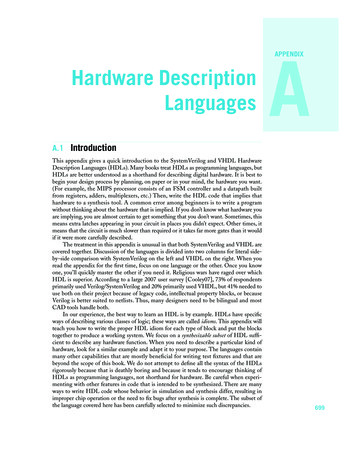
A.1Introduction701The true power of HDLs comes from the higher level of abstraction that they offer ascompared to schematics. For example, a 32-bit adder schematic is a complicated structure.The designer must choose what type of adder architecture to use. A carry ripple adder has32 full adder cells, each of which in turn contains half a dozen gates or a bucketful of transistors. In contrast, the adder can be specified with one line of behavioral HDL code, asshown in Example A.2.Example A.2 32-Bit AdderSystemVerilogVHDLmodule adder(input logic [31:0] a,input logic [31:0] b,output logic [31:0] y);library IEEE; use IEEE.STD LOGIC 1164.all;use IEEE.STD LOGIC UNSIGNED.all;entity adder isport(a, b: in STD LOGIC VECTOR(31 downto 0);y:out STD LOGIC VECTOR(31 downto 0));end;assign y a b;endmoduleNote that the inputs and outputs are 32-bit busses.architecture synth of adder isbeginy a b;end;Observe that the inputs and outputs are 32-bit vectors. They mustbe declared as STD LOGIC VECTOR.A.1.2 Simulation and SynthesisThe two major purposes of HDLs are logic simulation and synthesis. During simulation, inputs are applied to a module and the outputs are checkedto verify that the module operates correctly. During synthesis, the textualdescription of a module is transformed into logic gates.A.1.2.1 Simulation. Figure A.1 shows waveforms from a ModelSimsimulation of the previous sillyfunction module demonstrating thatthe module works correctly. Y is true when A, B, and C are 000, 100, or101, as specified by the Boolean equation.A.1.2.2 Synthesis. Logic synthesis transforms HDL code into a netlistdescribing the hardware; e.g., logic gates and the wires connectingthem. The logic synthesizer may perform optimizations to reduce theamount of hardware required. The netlist may be a text file, or it may bedisplayed as a schematic to help visualize the circuit. Figure A.2 showsthe results of synthesizing the sillyfunction module with SynplifyPro. Notice how the three 3-input AND gates are optimized down to apair of 2-input ANDs. Similarly, Figure A.3 shows a schematic for theadder module. Each subsequent code example in this appendix is followed by the schematic that it implies.a[31:0] b[31:0]y 1[31:0]FIGURE A.3 Synthesized addery[31:0]FIGURE A.1 Simulation waveformsbcyun5 yyaun8 yFIGURE A.2 Synthesized silly function circuit
702Appendix AHardware Description LanguagesA.2 Combinational LogicThe outputs of combinational logic depend only on the current inputs; combinationallogic has no memory. This section describes how to write behavioral models of combinational logic with HDLs.A.2.1 Bitwise OperatorsBitwise operators act on single-bit signals or on multibit busses. For example, the invmodule in Example A.3 describes four inverters connected to 4-bit busses.Example A.3 InvertersSystemVerilogVHDLmodule inv(input logic [3:0] a,output logic [3:0] y);library IEEE; use IEEE.STD LOGIC 1164.all;assign y a;endmoduleentity inv isport(a: in STD LOGIC VECTOR(3 downto 0);y: out STD LOGIC VECTOR(3 downto 0));end;architecture synth of inv isbeginy not a;end;a[3:0]y[3:0]y[3:0]FIGURE A.4 invThe gates module in HDL Example A.4 demonstrates bitwise operations acting on4-bit busses for other basic logic functions.Example A.4 Logic GatesSystemVerilogVHDLmodule gates(input logic [3:0] a, b,output logic [3:0] y1, y2,y3, y4, y5);library IEEE; use IEEE.STD LOGIC 1164.all;/* Five different two-input logicgates acting on 4 bit busses */assign y1 a & b;// ANDassign y2 a b;// ORassign y3 a b;// XORassign y4 (a & b); // NANDassign y5 (a b); // NORendmodule , , and are examples of SystemVerilog operators, while a, b, andy1 are operands. A combination of operators and operands, such asa & b, or (a b) are called expressions. A complete commandsuch as assign y4 (a & b); is called a statement.entity gates isport(a, b:in STD LOGIC VECTOR(3 downto 0);y1, y2, y3, y4,y5: out STD LOGIC VECTOR(3 downto 0));end;architecture synth of gates isbegin-- Five different two-input logic gates-- acting on 4 bit bussesy1 a and b;y2 a or b;y3 a xor b;y4 a nand b;y5 a nor b;end;
A.2Combinational Logic703SystemVerilog (continued)VHDL (continued)assign out in1 op in2; is called a continuous assignmentstatement. Continuous assignment statements end with a semicolon. Any time the inputs on the right side of the in a continuousassignment statement change, the output on the left side is recomputed. Thus, continuous assignment statements describe combinational logic.not, xor, and or are examples of VHDL operators, while a, b, andy1 are operands. A combination of operators and operands, such asa and b, or a nor b are called expressions. A complete command such as y4 a nand b; is called a statement.out in1 op in2; is called a concurrent signal assignment statement. VHDL assignment statements end with a semicolon. Any time the inputs on the right side of the in a concurrentsignal assignment statement change, the output on the left side isrecomputed. Thus, concurrent signal assignment statementsdescribe combinational :0]y1[3:0]y5[3:0]y2[3:0]y5[3:0]y2[3:0]FIGURE A.5 GatesA.2.2 Comments and White SpaceExample A.4 showed how to format comments. SystemVerilog and VHDL are not pickyabout the use of white space; i.e., spaces, tabs, and line breaks. Nevertheless, properindenting and use of blank lines is essential to make nontrivial designs readable. Be consistent in your use of capitalization and underscores in signal and module names.SystemVerilogVHDLSystemVerilog comments are just like those in C or Java. Commentsbeginning with /* continue, possibly across multiple lines, to thenext */. Comments beginning with // continue to the end of theline.SystemVerilog is case-sensitive. y1 and Y1 are different signals in SystemVerilog. However, using separate signals that only differ in their capitalization is a confusing and dangerous practice.VHDL comments begin with -- and continue to the end of the line.Comments spanning multiple lines must use -- at the beginning ofeach line.VHDL is not case-sensitive. y1 and Y1 are the same signal inVHDL. However, other tools that may read your file might be casesensitive, leading to nasty bugs if you blithely mix uppercase andlowercase.A.2.3 Reduction OperatorsReduction operators imply a multiple-input gate acting on a single bus. For example,Example A.5 describes an 8-input AND gate with inputs a0, a1, ., a7.
704Appendix AHardware Description LanguagesExample A.5 8-Input ANDSystemVerilogVHDLmodule and8(input logic [7:0] a,output logicy);VHDL does not have reduction operators. Instead, it provides thegenerate command (see Section A.8). Alternately, the operationcan be written explicitly:assign y &a;library IEEE; use IEEE.STD LOGIC 1164.all;// &a is much easier to write than// assign y a[7] & a[6] & a[5] & a[4] &//a[3] & a[2] & a[1] & a[0];endmoduleentity and8 isport(a: in STD LOGIC VECTOR(7 downto 0);y: out STD LOGIC);end;As one would expect, , , &, and reduction operators areavailable for OR, XOR, NAND, and NOR as well. Recall that a multiinput XOR performs parity, returning TRUE if an odd number ofinputs are TRUE.a[7:0][7:0]architecture synth of and8 isbeginy a(7) and a(6) and a(5) and a(4) anda(3) and a(2) and a(1) and a(0);end;[0][1][2][3][4][5][6][7]yyFIGURE A.6 and8A.2.4 Conditional AssignmentConditional assignments select the output from among alternatives based on an input calledthe condition. Example A.6 illustrates a 2:1 multiplexer using conditional assignment.Example A.6 2:1 MultiplexerSystemVerilogVHDLThe conditional operator ?: chooses, based on a first expression,between a second and third expression. The first expression iscalled the condition. If the condition is 1, the operator chooses thesecond expression. If the condition is 0, the operator chooses thethird expression.?: is especially useful for describing a multiplexer because,based on a first input, it selects between two others. The followingcode demonstrates the idiom for a 2:1 multiplexer with 4-bit inputsand outputs using the conditional operator.Conditional signal assignments perform different operationsdepending on some condition. They are especially useful fordescribing a multiplexer. For example, a 2:1 multiplexer can useconditional signal assignment to select one of two 4-bit inputs.module mux2(input logic [3:0] d0, d1,input logics,output logic [3:0] y);assign y s ? d1 : d0;endmoduleIf s 1, then y d1. If s 0, then y d0.library IEEE; use IEEE.STD LOGIC 1164.all;entity mux2 isport(d0, d1:in STD LOGIC VECTOR(3 downto 0);s:in STD LOGIC;y:out STD LOGIC VECTOR(3 downto 0));end;architecture synth of mux2 isbeginy d0 when s '0' else d1;end;
A.2Combinational Logic705SystemVerilog (continued)VHDL (continued)?: is also called a ternary operator because it takes threeinputs. It is used for the same purpose in the C and Java programming languages.The conditional signal assignment sets y to d0 if s is 0. Otherwise itsets y to d1.sd0[3:0]0d1[3:0]1y[3:0]y[3:0]FIGURE A.7 mux2Example A.7 shows a 4:1 multiplexer based on the same principle.Example A.7 4:1 MultiplexerSystemVerilogVHDLA 4:1 multiplexer can select one of four inputs using nested conditional operators.A 4:1 multiplexer can select one of four inputs using multiple elseclauses in the conditional signal assignment.module mux4(input logic [3:0] d0, d1, d2, d3,input logic [1:0] s,output logic [3:0] y);library IEEE; use IEEE.STD LOGIC 1164.all;entity mux4 isport(d0, d1,d2, d3: in STD LOGIC VECTOR(3 downto 0);s:in STD LOGIC VECTOR(1 downto 0);y:out STD LOGIC VECTOR(3 downto 0));end;assign y s[1] ? (s[0] ? d3 : d2): (s[0] ? d1 : d0);endmoduleIf s[1] 1, then the multiplexer chooses the first expression,(s[0] ? d3 : d2). This expression in turn chooses either d3 ord2 based on s[0] (y d3 if s[0] 1 and d2 if s[0] 0). Ifs[1] 0, then the multiplexer similarly chooses the second expression, which gives either d1 or d0 based on s[0].architecture synth1 of mux4 isbeginy d0 when s "00" elsed1 when s "01" elsed2 when s "10" elsed3;end;VHDL also supports selected signal assignment statements to provide a shorthand when selecting from one of several possibilities.They are analogous to using a case statement in place of multipleif/else statements in most programming languages. The 4:1multiplexer can be rewritten with selected signal assignment asarchitecture synth2 of mux4 isbeginwith s select y d0 when "00",d1 when "01",d2 when "10",d3 when others;end;
706Appendix AHardware Description Languages[0]s[1:0][1:0][1]un1 s 2d3[3:0]ed[1]ed[0]un1 s 3y[3:0]edd1[3:0]d2[3:0]d0[3:0]edy[3:0][0][1]un1 s 4[0][1]un1 s 5FIGURE A.8 mux4Figure A.8 shows the schematic for the 4:1 multiplexer produced by Synplify Pro.The software uses a different multiplexer symbol than this text has shown so far. The multiplexer has multiple data (d) and one-hot enable (e) inputs. When one of the enables isasserted, the associated data is passed to the output. For example, when s[1] s[0] 0,the bottom AND gate un1 s 5 produces a 1, enabling the bottom input of the multiplexerand causing it to select d0[3:0].A.2.5 Internal VariablesOften, it is convenient to break a complex function into intermediate steps. For example, afull adder, described in Section 11.2.1, is a circuit with three inputs and two outputsdefined by the equationsS A B C inC out AB AC in BC in(A.1)If we define intermediate signals P and GP A BG AB(A.2)
A.2Combinational Logic707we can rewrite the full adder asS P C in(A.3)C out G PC inP and G are called internal variables because they are neither inputs nor outputs but areonly used internal to the module. They are similar to local variables in programming languages. Example A.8 shows how they are used in HDLs.Example A.8 Full AdderSystemVerilogVHDLIn SystemVerilog, internal signals are usually declared as logic.In VHDL, signals are used to represent internal variables whose values are defined by concurrent signal assignment statements suchas p a xor b.module fulladder(input logic a, b, cin,output logic s, cout);library IEEE; use IEEE.STD LOGIC 1164.all;logic p, g;entity fulladder isport(a, b, cin: in STD LOGIC;s, cout:out STD LOGIC);end;assign p a b;assign g a & b;assign s p cin;assign cout g (p & cin);endmodulearchitecture synth of fulladder issignal p, g: STD LOGIC;beginp a xor b;g a and b;s p xor cin;cout g or (p and cin);end;sgscincoutabpun1 coutcoutFIGURE A.9 fulladderHDL assignment statements (assign in SystemVerilog and in VHDL) take placeconcurrently. This is different from conventional programming languages like C or Java inwhich statements are evaluated in the order they are written. In a conventional language, itis important that S P C in comes after P A B because the statements are executed sequentially. In an HDL, the order does not matter. Like hardware, HDL assignment statements are evaluated any time the signals on the right-hand side change theirvalue, regardless of the order in which they appear in a module.
708Appendix AHardware Description LanguagesA.2.6 Precedence and Other OperatorsNotice that we parenthesized the cout computation to define the order of operations asCout G (P · C in), rather than Cout (G P ) · C in. If we had not used parentheses, thedefault operation order is defined by the language. Example A.9 specifies this operatorprecedence from highest to lowest for each language.Example A.9 Operator PrecedenceSystemVerilogVHDLTABLE A.1 SystemVerilog operator precedenceTABLE A.2 VHDL operator precedenceOpHighestLowest *, /, % , , , MeaningNOTMUL, DIV, MODPLUS, MINUSLogical Left / Right ShiftArithmetic Left / Right Shift , , , Relative Comparison , ! Equality Comparison&, &AND, NAND , XOR, XNOR , OR, NOR?:ConditionalThe operator precedence for SystemVerilog is much like you wouldexpect in other programming languages. In particular, as shown inTable A.1, AND has precedence over OR. We could take advantageof this precedence to eliminate the parentheses.assign cout g p & cin;OpHighestLowestnot*, /,mod, remMeaningNOTMUL, DIV,MOD, REM , -,&PLUS, MINUS,CONCATENATErol, ror,srl, sll,sra, slaRotate,Shift logical,Shift arithmetic , / , , , , Comparisonand, or,nand, nor,xorLogicalOperationsAs shown in Table A.2, multiplication has precedence over additionin VHDL, as you would expect. However, all of the logical operations(and, or, etc.) have equal precedence, unlike what one mightexpect in Boolean algebra. Thus, parentheses are necessary; otherwise cout g or p and cin would be interpreted from leftto right as cout (g or p) and cin.Note that the precedence tables include other arithmetic, shift, and comparison operators. See Chapter 11 for hardware implementations of these functions. Subtractioninvolves a two’s complement and addition. Multipliers and shifters use substantially morearea (unless they involve easy constants). Division and modulus in hardware is so costlythat it may not be synthesizable. Equality comparisons imply N 2-input XORs to determine equality of each bit and an N-input AND to combine all of the bits. Relative comparison involves a subtraction.A.2.7 NumbersNumbers can be specified in a variety of bases. Underscores in numbers are ignored andcan be helpful to break long numbers into more readable chunks. Example A.10 explainshow numbers are written in each language.
A.2Combinational Logic709Example A.10 NumbersSystemVerilogVHDLAs shown in Table A.3, SystemVerilog numbers can specify theirbase and size (the number of bits used to represent them). The format for declaring constants is N'Bvalue, where N is the size in bits,B is the base, and value gives the value. For example 9'h25 indicates a 9-bit number with a value of 2516 3710 0001001012.SystemVerilog supports 'b for binary (base 2), 'o for octal (base 8),'d for decimal (base 10), and 'h for hexadecimal (base 16). If thebase is omitted, the base defaults to decimal.If the size is not given, the number is assumed to have asmany bits as the expression in which it is being used. Zeros areautomatically padded on the front of the number to bring it up to fullsize. For example, if w is a 6-bit bus, assign w 'b11 gives wthe value 000011. It is better practice to explicitly give the size. Anexception is that '0 and '1 are SystemVerilog shorthands for fillinga bus with all 0s and all 1s.In VHDL, STD LOGIC numbers are written in binary and enclosed insingle quotes. '0' and '1' indicate logic 0 and 1.STD LOGIC VECTOR numbers are written in binary or hexadecimal and enclosed in double quotes. The base is binary bydefault and can be explicitly defined with the prefix X for hexadecimal or B for binary, as shown in Table A.4.TABLE A.4 VHDL 22165516110110110101011TABLE A.3 SystemVerilog 010 1100.010101011.111A.2.8 Zs and XsHDLs use z to indicate a floating value. z is particularly useful for describing a tristatebuffer, whose output floats when the enable is 0. A bus can be driven by several tristatebuffers, exactly one of which should be enabled. Example A.11 shows the idiom for atristate buffer. If the buffer is enabled, the output is the same as the input. If the buffer isdisabled, the output is assigned a floating value (z).Example A.11 Tristate BufferSystemVerilogVHDLmodule tristate(input logic [3:0] a,input logicen,output tri[3:0] y);library IEEE; use IEEE.STD LOGIC 1164.all;assign y en ? a : 4'bz;endmoduleNotice that y is declared as tri rather than logic. logic signalscan only have a single driver. Tristate busses can have multipledrivers, so they should be declared as a net. Two types of nets in SystemVerilog are called tri and trireg. Typically, exactly one driveron a net is active at a time, and the net takes on that value. If no driveris active, a tri floats (z), while a trireg retains the previous value.If no type is specified for an input or output, tri is assumed.entity tristate isport(a: in STD LOGIC VECTOR(3 downto 0);en: in STD LOGIC;y: out STD LOGIC VECTOR(3 downto 0));end;architecture synth of tristate isbeginy "ZZZZ" when en '0' else a;end;
710Appendix AHardware Description Languagesena[3:0]y[3:0]y 1[3:0]FIGURE A.10 tristateSimilarly, HDLs use x to indicate an invalid logic level. If a bus is simultaneouslydriven to 0 and 1 by two enabled tristate buffers (or other gates), the result is x, indicatingcontention. If all the tristate buffers driving a bus are simultaneously OFF, the bus willfloat, indicated by z.At the start of simulation, state nodes such as flip-flop outputs are initialized to anunknown state (x in SystemVerilog and u in VHDL). This is helpful to track errors causedby forgetting to reset a flip-flop before its output is used.If a gate receives a floating input, it may produce an x output when it can’t determinethe correct output value. Similarly, if it receives an illegal or uninitialized input, it mayproduce an x output. Example A.12 shows how SystemVerilog and VHDL combine thesedifferent signal values in logic gates.Example A.12 Truth Tables with Undefined and Floating InputsSystemVerilogVHDLSystemVerilog signal values are 0, 1, z, and x. Constants startingwith z or x are padded with leading zs or xs (instead of 0s) to reachtheir full length when necessary.Table A.5 shows a truth table for an AND gate using all fourpossible signal values. Note that the gate can sometimes determinethe output despite some inputs being unknown. For example 0 & zreturns 0 because the output of an AND gate is always 0 if eitherinput is 0. Otherwise, floating or invalid inputs cause invalid outputs,displayed as x.VHDL STD LOGIC signals are '0', '1', 'z', 'x', and 'u'.Table A.6 shows a truth table for an AND gate using all fivepossible signal values. Notice that the gate can sometimes determine the output despite some inputs being unknown. For example,'0' and 'z' returns '0' because the output of an AND gate isalways '0' if either input is '0'. Otherwise, floating or invalidinputs cause invalid outputs, displayed as 'x' in VHDL. Uninitialized inputs cause uninitialized outputs, displayed as 'u' in VHDL.TABLE A.6 VHDL AND gate truthTABLE A.5 SystemVerilog ANDgate truth table with z and xANDA&Btable with z, x, and x0xxxuu0uuuuSeeing x or u values in simulation is almost always an indication of a bug or bad coding practice. In the synthesized circuit, this corresponds to a floating gate input or uninitialized state. The x or u may randomly be interpreted by the circuit as 0 or 1, leading tounpredictable behavior.
A.2Combinational Logic711A.2.9 Bit SwizzlingOften, it is necessary to operate on a subset of a bus or to concatenate, i.e., join together,signals to form busses. These operations are collectively known as bit swizzling. In Example A.13, y is given the 9-bit value c2c1d0d0d0c0101 using bit swizzling operations.Example A.13 Bit SwizzlingSystemVerilogVHDLassign y {c[2:1], {3{d[0]}}, c[0], 3'b101};y c(2 downto 1) & d(0) & d(0) & d(0) &c(0) & "101";The {} operator is used to concatenate busses.{3{d[0]}} indicates three copies of d[0].Don’t confuse the 3-bit binary constant 3'b101 with bus b.Note that it was critical to specify the length of 3 bits in the constant;otherwise, it would have had an unknown number of leading zerosthat might appear in the middle of y.If y were wider than 9 bits, zeros would be placed in the mostsignificant bits.The & operator is used to concatenate (join together) busses. ymust be a 9-bit STD LOGIC VECTOR. Do not confuse & with theand operator in VHDL.Example A.14 shows how to split an output into two pieces using bit swizzling andExample A.15 shows how to sign extend a 16-bit number to 32 bits by copying the mostsignificant bit into the upper 16 positions.Example A.14 Output SplittingSystemVerilogVHDLmodule mul(input logic [7:0] a, b,output logic [7:0] upper, lower);library IEEE; use IEEE.STD LOGIC 1164.all;use IEEE.STD LOGIC UNSIGNED.all;assign {upper, lower} a*b;endmoduleentity mul isport(a, b: in STD LOGIC VECTOR(7 downto 0);upper, lower:out STD LOGIC VECTOR(7 downto 0));end;architecture behave of mul issignal prod: STD LOGIC VECTOR(15 downto 0);beginprod a * b;upper prod(15 downto 8);lower prod(7 downto 0);end;[7:0]a[7:0]b[7:0][15:0]*lower 1[15:0]FIGURE A.11 Multipliers[15:8]lower[7:0]upper[7:0]
712Appendix AHardware Description LanguagesExample A.15 Sign ExtensionSystemVerilogVHDLmodule signextend(input logic [15:0] a,output logic [31:0] y);library IEEE; use IEEE.STD LOGIC 1164.all;entity signext is -- sign extenderport(a: in STD LOGIC VECTOR (15 downto 0);y: out STD LOGIC VECTOR (31 downto 0));end;architecture behave of signext isbeginy X"0000" & a when a (15) '0' else X"ffff" & a;end;assign y {{1
became an IEEE standard in 1995 and was updated in 2001 [IEEE1364-01]. In 2005, it was updated again with minor clarifica-tions; more importantly, SystemVerilog [IEEE 1800-2009] was intro-duced, which streamlines many of the annoyances of Verilog and adds high-level programming