Transcription
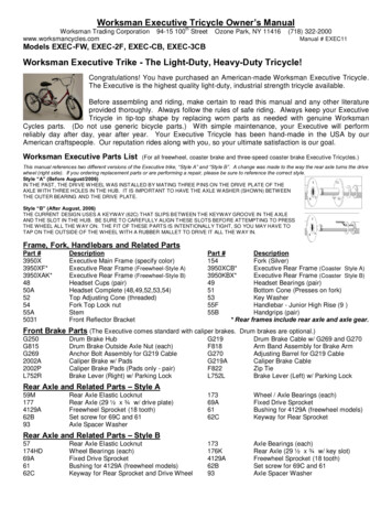
Worksman Executive Tricycle Owner’s ManualWorksman Trading Corporation – 94-15 100th Street – Ozone Park, NY 11416 – (718) 322-2000www.worksmancycles.comManual # EXEC11Models EXEC-FW, EXEC-2F, EXEC-CB, EXEC-3CBWorksman Executive Trike - The Light-Duty, Heavy-Duty Tricycle!Congratulations! You have purchased an American-made Worksman Executive Tricycle.The Executive is the highest quality light-duty, industrial strength tricycle available.Before assembling and riding, make certain to read this manual and any other literatureprovided thoroughly. Always follow the rules of safe riding. Always keep your ExecutiveTricycle in tip-top shape by replacing worn parts as needed with genuine WorksmanCycles parts. (Do not use generic bicycle parts.) With simple maintenance, your Executive will performreliably day after day, year after year. Your Executive Tricycle has been hand-made in the USA by ourAmerican craftspeople. Our reputation rides along with you, so your ultimate satisfaction is our goal.Worksman Executive Parts List(For all freewheel, coaster brake and three-speed coaster brake Executive Tricycles.)This manual references two different versions of the Executive trike, “Style A” and “Style B”. A change was made to the way the rear axle turns the drivewheel (right side). If you ordering replacement parts or are performing a repair, please be sure to reference the correct style.Style “A” (Before August/2006)IN THE PAST, THE DRIVE W HEEL W AS INST ALLED BY MATING THREE PINS ON THE DRIVE PLATE OF THEAXLE W ITH THREE HOLES IN THE HUB. IT IS IMPORTANT TO HAVE THE AXLE W ASHER (SHOW N) BETW EENTHE OUTER BEARING AND THE DRIVE PLATE.Style “B” (After August, 2006)THE CURRENT DESIGN USES A KEYWAY (62C) THAT SLIPS BETWEEN THE KEYW AY GROOVE IN THE AXLEAND THE SLOT IN THE HUB. BE SURE TO CAREFULLY ALIGN THESE SLOTS BEFORE ATTEMPTING TO PRESSTHE WHEEL ALL THE W AY ON. THE FIT OF THESE PARTS IS INTENTIONALLY TIGHT, SO YOU MAY HAVE TOTAP ON THE OUTSIDE OF THE W HEEL W ITH A RUBBER MALLET TO DRIVE IT ALL THE W AY IN.Frame, Fork, Handlebars and Related PartsPart ecutive Main Frame (specify color)Executive Rear Frame (Freewheel-Style A)Executive Rear Frame (Freewheel-Style B)Headset Cups (pair)Headset Complete (48,49,52,53,54)Top Adjusting Cone (threaded)Fork Top Lock nutStemFront Reflector BracketPart #Description154Fork (Silver)3950XCB*Executive Rear Frame (Coaster–Style A)3950KBX*Executive Rear Frame (Coaster–Style B)49Headset Bearings (pair)51Bottom Cone (Presses on fork)53Key Washer55FHandlebar - Junior High Rise (9”)55BHandgrips (pair)* Rear frames include rear axle and axle gear.Front Brake Parts (The Executive comes standard with caliper brakes. Drum brakes are optional.)G250G815G2692002A2002PL752RDrum Brake HubDrum Brake Outside Axle Nut (each)Anchor Bolt Assembly for G219 CableCaliper Brake w/ PadsCaliper Brake Pads (Pads only - pair)Brake Lever (Right) w/ Parking LockG219F818G270G219AF822L752LDrum Brake Cable w/ G269 and G270Arm Band Assembly for Brake ArmAdjusting Barrel for G219 CableCaliper Brake CableZip TieBrake Lever (Left) w/ Parking Lock17369A6162CWheel / Axle Bearings (each)Fixed Drive SprocketBushing for 4129A (freewheel models)Keyway for Rear Sprocket173176K4129A62B93Axle Bearings (each)Rear Axle (29 ½” x ¾” w/ key slot)Freewheel Sprocket (18 tooth)Set screw for 69C and 61Axle Spacer WasherRear Axle and Related Parts – Style A59M1774129A62B93Rear Axle Elastic LocknutRear Axle (29 ½” x ¾” w/ drive plate)Freewheel Sprocket (18 tooth)Set screw for 69C and 61Axle Spacer WasherRear Axle and Related Parts – Style B57174HD69A6162CRear Axle Elastic LocknutWheel Bearings (each)Fixed Drive SprocketBushing for 4129A (freewheel models)Keyway for Rear Sprocket and Drive Wheel
Worksman Trading Corporation – 94-15 100th Street – Ozone Park, NY 11416 – (718) 322-2000www.worksmancycles.comManual # EXEC07Coaster Brake Parts301SS13N-11 Speed Coaster Brake Hub3 Speed Cable and Trigger for 404N404NSS7213 Speed Coaster Brake Hub - ShimanoCoaster Brake Internal Kit (for 15Deluxe Sealed Crank Set (Upgrade)Complete Crank Set (36T,1265,3275,1380C)Stationary Washer (inside)Adjusting Cone (threaded, outside)Crank LocknutSprocket 36 Tooth (1/8”)ChainguardChain Half Link (1/8”)Chain (coaster brake - long)Chain Adjusters (for coaster addle (13” wide w/ springs - optional)Seatpost Clamp (seatpost to seat)Seatpost Clamp (seatpost to frame)Removable Front Basket (14.5”x9.5”x9”)Front Wire Basket (18”x13”x6”)Front Fender U-BraceFront “L” Bracket (fender to fork)Bolt, Nut, Washer (“L” bracket to fork)Rear Fender Brace / Clamp (one side)Complete Rear Fender Kit (24”)466AX469DAX469KAX4922E4922EKV1017B24” Front Wheel w/ Drum Brake24” Drive Wheel (Style A)24” Drive Wheel (Style B)24”x2.125” Tire24”x2.125” Kevlar Tire (Optional)24” Rim 766001Squeeze Bulb HornCable and Lock setReflector Set w/ Mounting HardwareBicycle HelmetFlashing Strobe Light (red lens)Glowspeck Light-Up Flashing PedalsSpoke WrenchCrank Cone WrenchBackrest w/ Mounting HardwareBattery Operated HeadlightPatch Kit (50)Crank Parts (Pedal Section) and rank Parts (1266,1268,1269,1271,1272,1273,1274)Crank Bearings (pair)Cups for Crank Housing (pair)Key Washer (outside)Stationary Cone (inside)Crank (one piece, forged - 5.5”)Pedals (pair)Chain Connecting Link (1/2”x1/8”)Chain (freewheel models)Chain (coaster brake - short)Seats, Seatpost, Baskets, and Saddle (13” wide w/o springs - standard)Seatpost (15”x1”x7/8”)Bolt, Nut, Washer for 4911CRear Wire Basket (21”x15”x9”)Front Wire Basket (21”x15”x9”)Front FenderFront Fender Hardware Kit (95, 4907, 4907A)Bolts, Nut, Washer (U-brace to fender)Rear FenderBolt, Nut, Washer (rear fender to brace)Wheels, Tires, and TubesM24FX469AX469AX-5/8M24A4923E6023B101824” Front Wheel w/o Drum Brake24” Free Side Wheel (Style A)24” Free Side Wheel (Style B)24” Rim (rim only – no spokes or hub)24”x2.125” Tube24”x2.125” Puncture Resistant TubeValve CapSafety and Comfort 0100139753961Ding Dong Chime BellMega-Horn (battery operated)Rear View MirrorSafety Flag on PoleFlashing Strobe Light (clear lens)Pedals with Velcro Foot Straps (pair)Air Foot PumpChain Rivet Remover ToolPedal WrenchGenerator Light SetCup Holder (tube-mounted)Part #’s and specifications subject to change without notice as we are constantly seeking ways to improve our products.
ASSEMBLY INSTRUCTIONS FOR THE WORKSMAN EXECUTIVE TRICYCLE :Please read this manual carefully prior to performing the simple finishing assembly and prior to riding. We recommend that a qualifiedbicycle mechanic assemble this cycle. Carefully remove the tricycle components from the carton, and follow the instructions in theorder presented. Keep in mind that the “left” or “right” side of the cycle is when viewed from the rear.TOOLS REQUIRED FOR ASSEMBLYSocket SetFlat-head screwdriverPliersAdjustable wrenchAir pumpBicycle greasePhillips screwdriverAllen wrench setSand paper or emery clothPACKAGINGThis tricycle comes packaged in two cartons. Check to make sure the following parts are included in each carton:Carton A- Front frame with pre-assembled seatpost binder bolt, chainguard, sprocket, and cranks- Front fork with pre-assembled wheel, tire, fender, caliper or drum brake, cable, lever, and headset- Rear wheels with tires (Free spinning wheel has two bearings. Drive wheel has one bearing.)Carton B- Rear Basket- Seatpost and seat- Grips- Handlebar- Stem- Pedals- Rear Frame Assembly (Frame, axle, axle nuts, fixed drive or freewheel sprocket)- Coaster brake kit (single or three speed, when tricycle is ordered as coaster brake model)- HardwareRear Frame Assembly to Front Framea) 2 hex bolts (3/4” x 3/8”)c) 2 hex bolts (1” x 3/8”)b) 4 flanged serrated nuts (3/8”)d) 6 washers (3/8”)Chain Partsa) Long chain (121 links – freewheel OR 103 links – coaster brake)b) Short chain (41 link – coaster brake models ONLY)c) Chain connecting links (1 for freewheel models OR 2 for coaster brake models)1) FRAME ASSEMBLY: (See illustration.)1. Remove the four 3/8” bolt/nut/washer combinations pre-mounted to therear section of the frame.2. Loosely attach rear section of frame with axle-side facing down andbasket mounting straps facing up. Install bolt/nut/washer as shown.(Note change in direction for front and rear. Bolts go in from oppositedirections on each side of frame.)2)TRANSMISSION ASSEMBLY: (See illustration. For freewheel models, connect chain with supplied connecting link from frontsprocket to rear freewheel sprocket on rear axle and proceed to step 6b of the Transmission Assembly instructions.)1. Attach coaster brake hub onto frame with brake arm facing forward on the left side of the tricycle.2. Install chain tensioners on each side of the coaster brake hub axle and place tensioner clips over threaded end oftensioner and around coaster brake dropout tips. Install two nuts on each tensioner.3. Connect the long chain with the supplied connecting link from the front sprocket (cranks) to the right-side sprocketof the coaster brake hub.4. Tighten chain by tightening the first two nuts on each chain tensioner. DO NOTOVERTIGHTEN THE CHAIN. IT SHOULD HAVE APPROXIMATELY ¼” OF SLACK ATTHE TOP/CENTER OF CHAIN, BUT NO MORE THAN 3/8”. (See illustration.)5. Attach brake arm to frame by bending brake strap around frame and fixing into position with provided nut and bolt.6. a) Connect short rear chain from coaster brake hub to rear axle using provided connecting link.b) Pull back slightly on rear section of frame and tighten the four nut/bolt/washer combinations from Step 1.7. On coaster brake models, align fixed drive gear on rear axle with coaster brake drive gear.8. Slide keyway between axle and fixed drive gear in slot on axle. Install set screw into fixed drive gear and tightenwith Allen key. MAKE SURE KEYWAY IS FULLY UNDER BUSHING.If you have a single speed coaster brake or freewheel Executive, proceed to the Attach Rear Wheels section of these instructions.
For three speed coaster brake models, see the Shimano or Sturmey Archer instruction booklet provided. Zip-tieshifter cable to underside of frame tubing leading up toward the handlebars. Cut off extra plastic on zip ties and spincut section, which may have sharp edges, toward bottom of frame.NOTE: If you have a freewheel model, you can upgrade to a 1 or 3 speed coaster brake at any time. Call 718-322-2000 for details.3) ATTACH REAR WHEELSThe right side drive wheel has one bearing on the outside, and the left side free-spinningwheel has two bearings. BE SURE TO INSTALL WASHERS BETWEEN THE OUTERFRAME BEARING AND EACH REAR WHEEL!- “Style A” axle has a plate welded to it on the right side with three prongs that match up tothree holes on the hub. Insert the prongs into the hub holes and install elastic axle nut.- “Style B” axle uses a keyway that slides between the groove in the hub and the groove inthe axle. Insert key and slide wheel on, being sure that slots are aligned. Install axlenut.Do not over-tighten axle nuts! Free-spinning wheel should spin very freely, but not move back and forth.4) TO ATTACH FRONT FORK/WHEEL ASSEMBLY TO THE FRAME:1) Grease cups (48) with Rustolene 200 lubricant or equal. Bearings (49) are pre-greased at thefactory, but it is always a good idea to add lubrication prior to assembly.2) Place one bearing (#49) onto the fork steering tube with the balls facing up.3) Slide the threaded fork (154) steering tube into the frame head.4) Place the other bearing on the top of the fork tube with the balls facing down towards the cup(#48), which is already pressed onto the frame.5) Install the top-adjusting cone (#52) onto the treaded fork steering tube. Hand-tighten, makingcertain the bearings do not bind. After hand tightening, turn back ¼ turn.6) Install the fork key washer (#53) and reflector bracket on top of the adjusting cone with tip ofwasher in slot on steering tube.7) Install head lock nut (#54) and securely tighten. Make sure that the fork rotates freely withoutbeing loose. Excess play or resistance must be adjusted. Failure to adjust properly can lead toimproper steering response.8) Install handlebar stem (55A) into the fork steering tube with the handlebar clamp facing forward. The stem must beinserted far enough to reach the minimum insertion line. Tighten the stem bolt slightly at this point. Loosen thehandlebar clamp nut and slide the handlebar through the clamp, centering the knurled center section of thehandlebar into the clamp.9) Position the handlebar to the desired angle and tighten clamp securely. Recommended torque is 300 IN. LBS.Adjust the handlebar rotation so that it is straight with the front wheel. Tighten stem bolt securely. Recommendedtorque 240 IN. LBS. Be sure not to over tighten, as damage to the parts may occur causing steering failure.10) Attach brake hand lever (and shift lever for 3 speed models) to handlebar and angle slightly downward. (Somebrake levers can be mounted on either side of handlebar.) Make sure cables are not tangled in any way.11) Make sure handlebars are clean and dry. Slide on handlebar grips until they are completely seated on handlebar.Do not use any lubricants, including soap, water, silicon, oil, etc. Do not use compressed air.5) INSTALLING PEDALS:Pedals are marked on the shaft with either an “L” or “R” denoting left orright. The “R” pedal fits on the right (sprocket side) of the crank arm.Tighten clockwise. The “L” pedal fits on the left side of the crank arm.Tighten counter-clockwise (left-hand thread). Securely tighten.Recommended torque 275 IN. LBS. CAUTION: Tightening in the wrongdirection will damage the crank and pedal threads.6) REAR FENDERS:Attach fender braces to axle housing using provided nuts, U-bolts, and washers. Bend braces if tire is rubbing thebrace.7) INSTALL REAR BASKET:1) Place basket on top of rear frame section.2) Place retention strap in basket and align holes in strap with holes in frame.3) Install bolt and washer through the top into nut and washer on the bottom, clampingframe between strap and frame. Bolt through snugly, but do not over-tighten.8) SEAT ADJUSTMENTS:1) Insert seatpost completely into seat clamp at bottom of seat. Tighten seat clamp bolt slightly.2) Insert seatpost into frame and tighten seat binder bolt. (Torque 240 inch lbs.)3) Adjust seat angle with nose of seat raised slightly upward and tighten seat clamp bolt. (Torque 240 inch lbs.)
4) Adjust the seat height to your desired level by loosening the seat clamp nut at the top of the frame’s seat tube. Retighten at desired height. Make sure a minimum of 3 1/2” of the post remains in the frame tube. There is a minimuminsertion line marked on the seatpost. Never adjust post above this level.9) FRONT BRAKE ADJUSTMENTThe front caliper brake has been pre-installed at the factory. However, it must be properly adjusted before and afteruse because cables will stretch with use and brake pads will eventually wear. It is recommended that a professionalbike mechanic inspect your brakes for proper adjustment. To use “Park” feature, when cycle is completely stopped,squeeze hand lever and push in parking plunger button on lever. To disengage, simply squeeze lever until parkingplunger button releases.MAINTENANCE TIPS:Always inspect your Worksman Cycle to ensure that all nuts, bolts, screws and hardware are tight and that no parts areworn or damaged. Do not attempt to straighten bent forks or frames.Chain:Lubricate chain once a month or as needed with light oil.Replace sprockets when teeth become worn, bent or broken.Keep chain adjusted so there is no more than 3/8” slack. Notethat we make the chains tight at the factory, as we do knowthey will stretch during the break-in period.Lubricate crank parts every six months. Replace pedals when the surface is worn or if axle becomes “tight” or frozen.Drum Brake:Some Worksman Executive tricycles may be equipped with a front drum brake. It is engaged bysqueezing the hand lever on the handlebar. To use “Park” feature, when cycle is completely stopped,squeeze hand lever and push in parking plunger button on lever. To disengage, simply squeeze leveruntil parking plunger button releases.Drum brakes are pre-adjusted at the factory. Readjust the cable tension as necessary using theadjusting barrel so that wheel spins freely and stops when brake is applied. Always replace worn brake cables anddamaged hand levers.Coaster Brake (if applicable):Coaster brakes hubs require little maintenance, but it is important to be aware of their condition to assure that they arebraking and accelerating properly. To activate this internal brake, reverse the pedaling motion until the brake engages.To avoid skidding and maintain control, apply care when braking. This is especially true on wet surfaces. Apply brakesgently, gradually increasing pressure. If you feel signs of slipping on acceleration, you should have your hub serviced orreplaced. When coaster brake hubs are new, it is common for them to squeal or sometimes make a vibrating, poppingnoise when braking because the brake pads are new. This sound will disappear with use. Replace coaster brakes whenthey become worn. Check chain tension regularly. For three speed units, pause pedaling when shifting to help meshgears. (Let the cycle coast.) This will make shifts smoother and will reduce wear and tear on the hub.Three-speed hubs have a low gear (Position 1), normal (or medium) gear (Position # 2), and a high gear (Position 3). Thedesired gear is selected by moving the lever(s) to these positions. When shifting, always stop pedaling or at least relaxchain pressure and move the shift lever to your next gear. It is recommended that you start in low gear and move upthrough the gears as you increase speed.Tires:Always check for worn or damaged tires. We recommend 40PSI as proper level of inflation unless tires specify otherwise.Replace tires that are worn or cut immediately. Replace or repair tubes that show leaks. Make sure valve is stickingstraight up from the rim and that tire is seated completely in the rim. Check air pressure with a good tire pressure gauge.When first inflating the tires, do so gradually, adding small amounts of air so as not to burst the tube or pop the tire off ofthe rim.Reflectors:See reflector kit for installation instructions. You should have 3 curved white reflectorsfor the wheels, one white square reflector for the front, and one square red reflector forthe rear. The rear reflector goes on the outside of the basket, and is held in place byattaching to the black rectangular bracket (with the small hole in the center) on theinside of the basket.Axle Bearings:Be sure to lubricate rear axle bearings and rear wheel bearings every six months. Use a bearing lubricant, which isavailable at any hardware or auto parts store. Failure to lubricate axle bearings can cause bearing to seize and cutthrough the axle. If you hear a grinding or hissing sound, lubricate bearings immediately or replace if damaged!
HERE ARE SOME OTHER EXCITING MODELS FROM WORKSMAN CYCLES!Chariot Parent / Child TrikeFolding Tandem BikeMover M2626 w/ Jumbo CabinetthWorksman Trading Corporation – 94-15 100 Street – Ozone Park, NY 11416 – (718) 322-2000www.worksmancycles.comParts list EXEC07LIMITED WARRANTY:THIS CYCLE IS W ARRANT IED AGAINST FAULT Y PARTS UNDER THE FOLLOW ING CONDITIONS: THIS W ARRANT Y DOES NOT COVER ANYFAILURE DUE TO ACCIDENT, ABUSE, MISUSE, NEGLECT OR AS THE RESULT OF NORMAL W EAR AND TEAR, OR IMPROPER ASSEMBLY.THE ENTIRE FRAME, INCLUDING ALL W ELDED JOINTS, IS WARRANT ED TO BE FREE FROM DEFECTS AND MATERIAL FOR ONE YEARWHILE IN POSSESSION OF THE ORIGINAL PURCHASER. ALL OTHER PARTS ON THIS CYCLE, EXCEPT TIRES AND TUBES, AREWARRANTIED FOR NINET Y DAYS FROM THE DATE OF PURCH ASE. REPAIR AND REPLACEMENT OF THESE PARTS IS TO BE ACCORDINGTHE WORKSMAN CYCLES PARTS AND SERVIC E PROCEDURE S AND MUST BE HANDLED DIRECT LY THROUGH THE SOURCE WHERE THECYCLE W AS PURCHASED. IF UPON EXAMINATION OF THE PARTS IN QUESTION, THE W ORKSMAN CYCLE DEALER DETERMINES THAT ITIS DEFECTIVE, EITHER REPAIR OR REPLACEMENT W ILL BE MADE AT NO COST EXCEPT THE COST OF TRANSPORTATION AND LABORCHARGES (IF ANY). UNAUTHORIZED REPAIRS OR REPLACEMENT AUTOMATICALLY VOIDS W ARRANTY. PROPER MAINTENANCE ISREQUIRED FOR W ARRANT Y TO BE VALID. IN THE EVENT THAT IT W AS DETERMINED THAT THE WARRANTY CLAIM IS THE RESULT OFMISUSE, ABUSE , IMPROPER MAINTENANCE OR SIMPLY NOT DEFECT IVE OR BEYOND THE W ARRANTY PERIOD, W ORKSMAN CYCLES ORTHE DEALER W ILL ADVISE YOU AS TO THE COST OF REPAIR, REPLACEMENT OR LABOR PRIOR TO PERFORMING ANY W ORK ORREPLAC ING ANY PARTS. IF YOU CHOOSE NOT TO HAVE THE DEALER OR W ORKSMAN CYCLES PERFORM THE W ORK, THE PARTS W ILLBE RETURNED TO YOU AT YOUR EXPENSE OR DISCARDED IF NO REPLY IS RECEIVED W ITHIN 2 WEEKS OF NOTIFICATION. THE SOLERESPONSIBILITY OF THE MANUFACTURER TO THE TERMS OF THIS W ARRANT Y, IF ANY, SHALL BE THE REPAIR AND/OR REPLACEMENTOF THE PARTS AS INDICATED ABOVE. THE LIABILITY OF THE MANUFACTURER SHALL IN NO EVENT EXCEED THE ORIGINAL PURC HASEPRICE OF THE PRODUCT, AND THE MANUFACT URER SHALL NOT BE RESPONSIBLE FOR ANY CONSEQUENTIAL DAMAGES OF ANYNATURE, INCLUD ING, BUT NOT BY W AY OF LIMITATION, DAMAGES FOR PERSONAL INJURY OR PROPERTY. THIS STATEMENTCONSTITUTES THE EXCLUSIVE EXPRESS ION OF W ARRANTIES BY THE MANUFACTURER AND IS IN LIEU OF ANY OR ALL OTHERWARRANTIES SUCH AS EXPRESSED W ARRANT IES, IMPLIED W ARRANT IES, INCLUDING BUT NOT LIMITED TO WARRANTIES OFMERCHANTABILITY, AND FITNESS OR PURPOSE, ARE LIMITED IN DURAT ION FOR ONE YEAR FROM THE DATE OF PURC HASE OF THEFRAME ONLY AND 90 DAYS FOR ALL OTHER PARTS, EXCEPT TIRES AND TUBES WHICH ARE NOT WARRANT ED. WORKSMAN TRADINGCORPORATION IS THE MANUFACT URER. MISUSE OF THE CYCLES INCLUDING OFF ROAD RIDING, INSTALLATION OF MOTORS OR POWERASSISTS, ALTERATIONS, REPAIRS USING PARTS OTHER THAN GENUINE W ORKSMAN CYCLE PARTS VOIDS W ARRANT Y. W ORKSMANTRADING CORPORATION IS NOT RESPONSIBLE FOR MAINTAINING RECORDS OF SERIAL NUMBERS. VOID W HERE PROHIBITED BY STATELAW.RULES FOR SAFE RIDING AND RESPONSIBLE OPERATION: Carefully read this manual before operating the It is the responsibility of the person who completes the assembly to properly install all parts included and to inspect the cycle prior to riding toinsure proper operation.Operator is responsible for required maintenance to keep the cycle in good operation condition.Observe all traffic regulations in the operating environment. (Stop signs, etc.)Keep to the right and in a straight line. Tricycles tend to pull toward the non-driven wheel side. This is normal. Ride in single file.Do not ride outdoors at night, and have appropriate signaling device as needed. (W e recommend the 3973 Mega Horn.)Give pedestrians the Right of W ay.Always look around you to understand the riding environment and hazards.Do not carry passengers, and check brakes prior to riding.Slow down when approaching turns or intersections. Tricycles are meant for slow pace rides, not for racing.Use proper hand signals when turning or stopping.Recommended safety options include, but are not limited to, an approved helmet, audible warning device, front/rear lights and/or reflectors.Never ride the cycle if there are known repairs required.Do not exceed the recommended weight capacity of the cycle. (250 lbs., including the rider.)Always secure cargo with appropriate tie down straps. StarLite Tricycles are not intended or warranteed for commercial use.Wipe surface of cycle clean and dry when exposed to corrosive substances or environment.Operate cycle at slow speeds, particularly in high traffic areas.Operators of cycles should be in good physical condition. Ride at your own risk.W ear proper riding attire. Check shoelaces and pant legs prior to riding so they do not become engaged in the chain and sprocket.Ride only on smooth, paved surfaces. Do not use off road.Do not operate a tricycle on steep grades. They are designed for relatively level, paved surfaces only.Always replace worn parts with genuine W orksman Cycle Repair Parts.Always keep both hands on the handlebars. Tricycles have a tendency to pull slightly to one side.Worksman highly recommends having the Executive tricycle built by a professional and experienced bicyclemechanic to avoid errors in assembly. Failure to have this tricycle professionally assembled by a qualifiedbicycle mechanic puts the rider at risk of injury or death.Visit us online at www.worksmancycles.com or call us at (888) 3-WHEELER!
This manual references two different versions of the Executive trike, Style A and Style B . A change was made to the way the rear axle turns the drive wheel (right side). If you ordering replacement parts or are performing a repair, please be sure to ref