Transcription
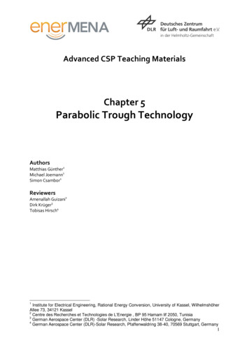
Advanced CSP Teaching MaterialsChapter 5Parabolic Trough TechnologyAuthorsMatthias Günther1Michael Joemann1Simon Csambor1ReviewersAmenallah Guizani2Dirk Krüger3Tobisas Hirsch41Institute for Electrical Engineering, Rational Energy Conversion, University of Kassel, WilhelmshöherAllee 73, 34121 Kassel2Centre des Recherches et Technologies de L’Energie , BP 95 Hamam lif 2050, Tunisia3German Aerospace Center (DLR) -Solar Research, Linder Höhe 51147 Cologne, Germany4German Aerospace Center (DLR)-Solar Research, Pfaffenwaldring 38-40, 70569 Stuttgart, Germany1
Table of ContentsSummary.61Introduction .72History of parabolic trough power plant technology .93Power plant components . 133.1Parabolic trough collector . 143.1.1 Collector geometry . 143.1.2 Mirror material . 223.1.3 Bearing structure . 273.1.4 Sun Tracking System . 403.2Receiver. 443.2.1 Receiver components. 453.2.2 Receiver efficiency . 513.3Heat transfer fluid. 553.3.1 Heat transfer fluid in indirect steam generation power plants . 553.3.2 Direct steam generation . 583.4Solar field . 643.4.1 Solar field orientation. 643.4.2 Solar field structure. 653.4.3 Solar field size. 6845Power plant integration . 714.1Solar field size, storage, solar multiple . 714.2Base load, intermediate load and peak load plant configuration . 734.3Hybridisation . 75Efficiency of parabolic trough power plants. 805.1Solar-to-electric efficiency . 805.2Solar field efficiency . 815.3Power block losses . 875.4Parasitic energy uses . 88Reference List . 89Annex . 941 Proof that a parabola has a focal point . 942 Proof that parabolas with the same rim angle are geometrically similar . 963 Derivation of the relation between rim angle, focal length and aperture width . 984 Derivation of the parabolic trough surface area . 98Questions . 1002
Answers . 102Exercises . 103Solutions . 1063
NomenclatureSymbolLatin lettersaAbCdfhIAMlsSSMTMeaningUnitaperture widthmsurface aream²active receiver surface aream²collector aperture aream²receiver aperture aream²aperture aream²total receiver surface aream²insulation thicknessmconcentration ratiogeometrical concentration ratioreceiver diametermfocal length of parabolic troughmdirect irradiance on the collector apertureW/m2irradiance in the Sun imageW/m2irradiance on receiverW/m2heat transfer coefficientincidence angle modifiercollector lengthmrated electrical powerWtotal energy inputWuseable energy outputWpower that is absorbed by the receiver glass tubeWconductive heat transferWconvective heat transferWconvective heat loss of the absorber tubeWconvective heat loss of the receiver glass tubeWoptical receiver lossWthermal receiver lossW/mheat transfer through radiationWpower loss due to radiant emittance of the absorberWpower loss due to radiant emittance of the receiver glass Wtubepower loss due to reflection on the absorberWpower loss due to reflection on the receiver glass tubeWuseable energy flowWdistance between absorber tube and mirror rimmtracking angle , radparabola length (trough cross-section)msolar multipleambient temperature C, Khigh temperature level in a thermodynamic cycle C, Ksurface temperature of heat transfer element C, Klow temperature level in a thermodynamic cycle C, Ktemperature C, K4
Greek lettersabsorptancesun beam angleweighted average absorptance for black-body radiation attemperature Tspectral absorptanceazimuth anglesolar azimuth angledispersion angleweighted average emissivity for black-body radiation at thetemperature Temissivity (in specific spectral range)efficiencypower block efficiencyoptical solar field efficiency at incidence anglesolar field efficiencymaximum thermal-to-mechanical conversion efficiencyincidence anglesolar zenith anglewavelengththermal conductivitycollector length use factorintercept variance factoroptical parameter variance factorreflectivityStefan-Boltzmann constanttransmittancerim anglehour LPCMPSASCASEGSSM’, rad ’, rad MW/(mK)W/(m² ) Archimede Solar EnergyBalance of plantConcentrating Solar PowerDirect Solar SteamGerman Aerospace CenterDirect Normal IrradiationDirect steam generationHeat Collection ElementHeat Transfer ElementHeat Transfer FluidIncidence Angle ModifierNational Renewable Energy LaboratoryPhase Change MaterialPlataforma Solar de AlmeríaSolar Collector AssemblySolar Energy Generating SystemSolar Multiple5
SummaryIn this section we will get to know the currently most frequent form of large scale CSP plants:parabolic trough power plants. We will learn about their history and their current status. We willunderstand their structure and how their components work. Important design parameters will beexplained. At the end, the efficiency of the generation of electricity with parabolic trough power plantswill be specified.Key questions Which is currently the dominating CSP technology?What are the milestones in the history of parabolic trough power plants?What are the main components of a parabolic trough power plant and how do they work?What are central parameters in the design of a parabolic trough power plant?How efficient are parabolic trough power plants?6
1 IntroductionParabolic trough power plants use parabolic trough collectors to concentrate the direct solar radiationonto a tubular receiver. Large collector fields supply the thermal energy, which is used to drive asteam turbine, which, on its part, drives the electric generator.Figure 1: Parabolic power plants in southern Spain (Andasol 1 and 2, in the back ground on the rightside the prepared construction ground for Andasol 3, source: Solar Millenium)Parabolic trough power plants constitute the biggest share of the installed concentrating solar powertechnology. Distinguishing between parabolic trough power plants, Fresnel power plants, solar towerpower plants and dish/Stirling systems, the parabolic trough power plants provide over 90% of thecapacity of concentrating solar power plant technology that is in operation or in construction inSeptember 2010. Among the planned additional capacity (at the same date) more than 50% areconstituted by parabolic trough power plants. The following figure shows the absolute numbers andthe shares of the four technology types among the plants in operation, in construction, in the planningstage, and, finally, the sum of all of them. 55Photon, Sept. 2010 ( German journal for solar technology)7
Figure 2: Percentage of different solar thermal power technologies8
2 History of parabolic trough power plant technologyJohn Ericsson constructed in 1880 the first known parabolic trough collector. He used it to power a hotair engine. In 1907, the Germans Wilhelm Meier and Adolf Remshardt obtained the first patent ofparabolic trough technology. The purpose was the generation of steam.6In 1913, the English F. Shuman and the American C.V. Boys constructed a 45 kW pumping plant forirrigation in Meadi, Egypt, which used the energy supplied by trough collectors. The pumps weredriven by steam motors, which received the steam from the parabolic troughs. The constructors usedparabolic trough collectors with a length of 62m and an aperture width of 4m. The total aperture areawas 1,200 m².7 The system was able to pump 27,000 litres of water per minute. 8Despite the success of the plant, it was shut down in 1915 due to the onset of World War I and alsodue to lower fuel prices, which made more rentable the application of combustion technologies.Figure 3: Parabolic trough collector application in Egypt built in 1913 (source: Ragheb 2011)The interest in the parabolic trough technology did not rise again until 1977, when the US Departmentof Energy as well as the German Federal Ministry of Research and Technology began to fund thedevelopment of several process heat machines and water pump systems with parabolic troughcollectors. Higher fossil fuel prices encouraged the governments to take new measures.Results of these measures were, for instance, the following:- Between 1977 and 1982, the company Acurex installed parabolic trough demonstrationsystems with a total aperture area of almost 10,000 m² in the USA for process heatapplications.- The first modern line-focusing solar power plant was a 150 kWe facility that was built in 1979in Coolidge/Arizona.9- Nine member states of the International Energy Agency participated in the project of buildingdemonstration facilities with a rated power of 500 kW at the Plataforma Solar de Almeria,which was put into operation in 1981.- The first private financed process heat machine with 5580 m² parabolic trough collectors wassuccessfully put into operation in 1983 in Arizona for thermal heating of electrolyte tanks in acopper processing company. 10 These trough systems developed for industrial process heatapplication were capable of generating temperatures higher than 260 C.In 1983, Southern California Edison (SCE) signed an agreement with Luz International Limited topurchase power from the first two commercial solar thermal power plants that should be constructed inthe Mojave Dessert in California. These power plants, called Solar Electric Generating System6See Geyer et al. 2002.See Nava et al. 1996.8See Ragheb 2011.9See Winter et al. 1991, p. 216.10See Geyer et al. 2002.79
(SEGS) I and II, started operation in the years 1985 and 1986. Later, Luz signed a number of standardoffer contracts with SCE that led to the development of the SEGS III to SEGS IX plants. Initially, theplant size was limited to 30 MW. It was later raised to 80 MW. In total, nine plants with a totalcapacity of 354 MW were built.11Figure 4: SEGS III–SEGS VII solar plants in California (source: Sandia National Laboratory)11See Price et al. 2002.10
Table 1: Characteristics of SEGS plants I – IX (Price et al. 2002)Solar field SolarSEG First year NetTurbineoutletfieldSofoutputefficienctemperatur areaPlant operation[MWe]y [%]2e [ C][m ut[GWhe]82 96031.5/ ility provided ilerGas-fired heattransferfluidheaterGas-fired heattransferfluidheaterUntil today these plants still continue in operation. The constructional and operational experience withthese plants pushed the parabolic trough technology a considerable step forward and provided thebasics for further technologic developments and project planning.A further expansion of the installed capacity of parabolic trough power plants did not take place until2007, when Nevada Solar One with a capacity of 64MWe was opened in Nevada.The first commercial parabolic trough power plant in Europe, Andasol I, is generating electricity sinceDecember 2008 at a high plane near the Sierra Nevada mountains in the Spanish Province of Granada.In the middle of 2009 Andasol II, which has the same capacity, was completed and connected to thegrid. It is located directly besides Andasol I. The same holds for Andasol III, which is underconstruction since September 2009.12 Each of the three plants has a capacity of 50 MWe. The Andasolpower plants were the first CSP power plants with large thermal storage systems. The solar multiple is2; heat can be stored for 7.5 full load hours. In summer, the power plants can be operated nearly 24hours a day.Current political support, which is reflected in the application of financial support schemes (like feedin-tariffs or renewable energy quotas), makes many new parabolic trough power plant projectspossible. Most of these projects are located in the USA or in Spain, but there are also several projectsunder construction or in planning phase in India, China, Egypt, Algeria, Morocco, Australia and othercountries.Additionally to electricity generation, parabolic troughs can also be used to provide process heat forindustrial processes. Process heat is required at different temperature levels. The major part of therequired process heat (e.g. in the chemical, food or textile industry) is needed in the mediumtemperature range between 80 to 250 C. Low temperature process heat ( 100 C) can be provided12See http://www.solarmillennium.de/index,lang2.html11
with non concentrating solar thermal collectors. Temperatures between 150 and 250 C, on thecontrary, require concentrating solar thermal collectors. There are several parabolic trough collectorsunder development for the medium temperature range. Usually these collectors are smaller than theparabolic trough collectors for electric power generation.An example is an application in the pharmaceutical industry in Cairo. It has the followingcharacteristics:Installed capacity:1330 kWCollector area:1900 m²Number of collectors:36Heat transfer medium:steamOperating temperature:173 COperating pressure:8 barsFigure 5: Process steam at a pharmaceutical company in Egypt (source: Weiss 2005)12
3 Power plant componentsThe energy flow in a parabolic trough power plant has the following structure: Direct solar radiation isconcentrated and converted into thermal energy. The thermal energy is converted into pressure energyof vapour, which is converted into kinetic energy. The kinetic energy is finally transformed intoelectrical energy, the final product of the power plant.These energy conversion steps are realized in the respective power plant components: The parabolictrough collector and the tracking system are essential for the concentration process. The receiverconverts the radiation energy into thermal energy. Heat transfer medium and thermal storage arecarriers of the thermal energy. The steam generator has the function to convert the thermal energy intopressure energy of a gaseous medium. This is done by the evaporation of water. The cooling systemhas the aim to complete the liquid/gaseous-cycle converting the steam back to water. The steamturbine converts the pressure energy in the steam into rotational energy. The electric generator, finally,converts the rotational energy into electric energy, which can be supplied to the electric grid. Thefollowing figure shows the mentioned main components of the plant and relates them to theirrespective place in the energy conversion chain.Figure 6: Energy conversion chain in a parabolic trough power plant and corresponding plantcomponentsIn this chapter, we will discuss the plant components that are specific for CSP plants. Theconventional power plant components were explained in the preceding chapter.13
3.1 Parabolic trough collector3.1.1Collector geometryThe collector, the parabolic trough, is a trough the cross-section of which has the shape of a part of aparabola. More exactly, it is a symmetrical section of a parabola around its vertex.Radiation concentration at a parabolic troughParabolic troughs have a focal line, which consists of the focal points of the parabolic cross-sections.Radiation that enters in a plane parallel to the optical plane13 is reflected in such a way that it passesthrough the focal line.Figure 7: Path of parallel rays at a parabolic mirrorA proof of the existence of a focal point is presented in the annex. An appropriate analyticrepresentation of a parabola is,where(1)is the focal length, i.e. the distance between the vertex of the parabola and the focal point.13With “optical plane” we mean the plane that contains the optical axes of the parabolic cross-sectionsof the trough.14
Parameters for the geometrical description of a parabolic troughIn order to describe a parabolic trough geometrically, the parabola has to be determined, the section ofthe parabola that is covered by the mirrors, and the length of the trough.The following four parameters are commonly used to characterize the form and size of a parabolictrough: trough length, focal length, aperture width, i.e. the distance between one rim and the other,and rim angle, i.e. the angle between the optical axis and the line between the focal point and themirror rim:Figure 8: Geometrical parabolic trough parametersThe length of the trough is an unproblematic measure and does not need any explanation.The focal length, i.e. the distance between the focal point and the vertex of a parabola, is a parameterthat determines the parabola completely (in the mentioned mathematical expression of a parabola,, the focal length f is the only parameter).Figure 9: Focal length as shape parameter15
The rim angle, i.e. the angle between the optical axis and the line between the focal point and themirror rim, has the interesting characteristics that it alone determines the shape of the cross-section ofa parabolic trough. That means that the cross-sections of parabolic troughs with the same rim angle aregeometrically similar. The cross-sections of one parabolic trough with a given rim angle can be madecongruent to the cross-section of another parabolic trough with the same rim angle by a uniformscaling (enlarging or shrinking). If only the shape of a collector cross-section is of interest, but not theabsolute size, then it is sufficient to indicate the rim angle. A proof that the cross-sections of parabolictroughs with the same rim angle are geometrically similar is presented in the annex.Two of the three parameters rim angle, aperture width and focal length are sufficient to determinethe cross-section of a parabolic trough completely, i.e. shape and size. This also means that two ofthem are sufficient to calculate the third one.can be expressed as a function of the ratio of theaperture width to the focal length:.(2)or, alternatively, the ratio of the aperture width to the focal length can be expressed as a function of therim angle:(3)The following diagram represents the a-f ratio in dependence on the rim angle.Figure 10: Relation between the rim angle and the a/f-valueGeometrical parameters of real parabolic troughsWe will have a look now at the values that take these parameters at real parabolic troughs.First, we see that the rim angle should neither be too small nor too large. The rim angle isrelated to the distance between the different parts of the mirrors and the focal line. Taking afixed aperture width the following figure represents this relation:16
Figure 11: Relation between the focal length and the rim angle for a constant trough aperture widthThe rim angle is a very important constructive trait of collectors. For instance, it has an effect on theconcentration ratio and on the total irradiance per meter absorber tube [W/m]. Qualitatively, we canunderstand in the following way that there must be some ideal rim angle range and that is shouldneither be too small nor too large:- We consider, first, perfect mirrors, disregarding possible slope errors. 14If the rim angle is very small, then the mirror is very narrow and it is obvious that a broadermirror (with a larger rim angle) would enhance the power projected onto the absorber tube. 15If the rim angle is very big, then the way of the reflected radiation from the outer parts of themirror is very long and the beam spread is very big, reducing, hence, the concentration ratio.A mirror with a smaller rim angle and the same aperture width would permit a higherconcentration ratio.14In the chapter “Solar Radiation” we demonstrated that at a rim angle of 45 the highestconcentration ratio is reached. This result, however, is valid only for plane receivers. At tubularreceivers the situation is different. The optimal rim angle is bigger because the problem of the Sunimage widening due to high incidence angles on the focal plane at high rim angles does not exist inthe same way.15Alternatively, the mirror could be allocated nearer to the absorber tube (with the same aperturewidth and a larger rim angle) and the beam spread (which exists due to the extension of the Sun disc)could be reduced, what would increase the concentration ratio.17
Figure 12: Dependence of the focal spot size on the rim angle(at a given trough aperture width)-Additionally, if we consider real mirrors with a certain degree of geometrical inexactness, thenit is important to maintain a low distance to the absorber also because the effect of thesegeometrical mirror errors. The larger the distance to the absorber, the more weight carries theradiation aberration due to mirror slope errors. Once more, at a given aperture width, verysmall rim angles as well as very large rim angles imply large distances between the mirror andthe focal line (in the case of very large rim angles for the outer parts of the mirror) and shouldbe avoided.18
Figure 13: Effects of slope errors in dependence on the rim angle-Last but not least there is an economical aspect that limits the reasonable rim angle: At highrim angles the outer parts have a low contribution to the energy yield in relation to the mirrorarea. That means a high investment is necessary, which contributes only little to the energyyield.So, there are several criteria, which together determine the rim angle. The rim angle of real parabolictroughs is around 80 .The aperture width of most actual collectors amounts to approximately 6m, the focal length is(correspondingly to the rim angle and aperture width values) approximately 1.75m, and the modulelength is between 12 and 14m. There are some collectors that have smaller (Solarlite) or largeraperture widths (Skyfuel, Heliotrough) with corresponding different focal lengths.Mirror area and aperture areaBesides the mentioned linear measures, also surface area measures are important. There is, first, theaperture area, which is an important constructive measure. At a given DNI and a given Sun position itdetermines the radiation capture. The aperture areais calculated as the product of the aperturewidth and the collector length :,(4)19
The surface area of a parabolic trough may be important to determine the material need for the trough.The area is calculated as follows:.(5)A derivation of this equation is presented in the annex.Concentration ratioThe concentration ratio is one of the central parameters of the collector. It is decisive for the possibleoperating temperatures of the parabolic trough power plant. The concentration ratiois defined asthe ratio of the radiant flux density at the focal line, or, what is the same, at the Sun image,, to thedirect irradiance at the aperture of the collector,:(6)Now, the irradiance is different in different points of the Sun image. That’s why we can consider, first,a punctual concentration ratio. In this case,has to be determined at a point within the focal line inorder to determine the concentration ratio in relation to that specific point. Or we can consider, second,a mean concentration ratio taking as the ratio of the mean irradiance at the focal line to the directnormal irradiance.Concerning the mean concentration ratio (contrary to the punctual one) there is an easy way to specifyit without any measurement: The geometrical concentration ratiois a useful approximation. It isdefined as the ratio of the collector aperture area to the receiver aperture area.(7)While it is clear what the collector aperture area is (see above), it is much less clear what has to countas the receiver aperture. In many cases, the projected area of the absorber tube is chosen. In this casethe receiver aperture area is a rectangle with the area, where is the absorber tube diameter.Figure 14: Collector aperture area and receiver aperture area20
The concentration ratio is, then:(8)In the chapter “Solar Radiation” it was demonstrated that the maximal mean concentration ratio inlinear focussing collectors, taking the Sun image area in the focal plane for, is 107.5. Themaximal geometrical concentration ratio in real systems, accepting the projected absorber tube area as, is 82.Another possibility is to take the irradiated absorber surface area as the receiver aperture area. In realparabolic troughs this would mean that the whole absorber tube surface areais the receiveraperture area16:.(9)This definition would lead to a lower geometrical concentration ratio. However, the concentration ratioaccording to the projected areas is more commonly used.16We take into consideration that the absorber tube is not only irradiated by the reflected radiation butalso by the radiation that reaches the tube directly so that the whole absorber tube surface isirradiated.21
3.1.2Mirror materialThe main requirements for appropriate mirror materials are their reflective properties. The reflectivitymust be high. The reflectivity of a surface is a number that indicates the fraction of the incidentradiation that is reflected by the surface. In general, the reflectivity is different for differentwavelengths so that it has to be specified for a given wavelength or a given wavelength range, forinstance for the visible light range. In the case of solar applications, the solar spectrum is of interest.Generally, a “solar weighted reflectivity” is indicated that takes into consideration that there aredifferent energy contents at different wavelengths in the solar spectrum. The solar weightedreflectivity indicates, hence, the fraction of solar energy that is reflected on a mirror.Furthermore, reflection can be distinguished in specular reflection and diffuse reflection. Specularreflection means that the light that comes from a single incoming direction is reflected into a singleoutgoing direction. Specular reflection is mirror-like reflection. According to the law of reflection thedirection of the incoming light and the direction of the outgoing light have the same angle with respectto the mirror surface normal. At diffuse reflection, on the contrary, the incoming light is reflected in abroad range of directions. In CSP applications, only specular reflectivity is of interest, because thereflected radiation must have a defined direction. The decisive quality criterion for efficient mirrors is,hence, the “solar weighted specular reflectivity”. 17Silver coated glass mirrorsThe most common parabolic mirrors today consist of silver coated glass mirrors. Indeed, all realizedcommercial parabolic trough power plants use them. There are experiences with these mirrors sincethe first parabolic trough power plants were built in the 1980s. The mirrors have proven to be durable:Even after more than ten years of operation they
purchase power from the first two commercial solar thermal power plants that should be constructed in the Mojave Dessert in California. These power plants, called Solar Electric Generating System 6 See Geyer et al. 2002. 7 See Nava et al. 1996. 8 See Ragheb 2011. 9