Transcription
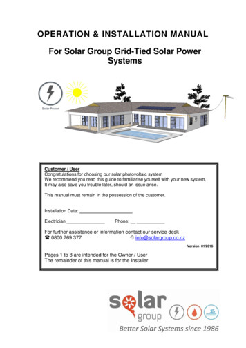
OPERATION & INSTALLATION MANUALFor Solar Group Grid-Tied Solar PowerSystemsCustomer / UserCongratulations for choosing our solar photovoltaic systemWe recommend you read this guide to familiarise yourself with your new system.It may also save you trouble later, should an issue arise.This manual must remain in the possession of the customer.Installation Date:ElectricianPhone:For further assistance or information contact our service desk 0800 769 377 info@solargroup.co.nzVersion 01/2016Pages 1 to 8 are intended for the Owner / UserThe remainder of this manual is for the Installer
IMPORTANT INFORMATIONThis owner’s manual is intended for operation of grid-tiedsolar power generation systems. Battery-backup and off-gridsystems require additional instructions.System users and professional installers should read thismanual carefully and strictly follow the instructions in themanual.This guide provides a first-hand reference point for commonquestions, solar power information, shutdown, andmaintenance information for owners and installers.Please keep this manual in a safe place for reference.This general manual provides important safety information relating to the installation,maintenance and handling of solar modules.Failure to follow these instructions may result in death, injury or property damage.The installation of solar modules requires specialized skills and should only beperformed by licensed professionals.LIMITATION OF LIABILITYThe information contained in this manual, and all other information or advice providedby Solar Group Ltd in connection with the purchase, installation, use, and service ofSolar Power generation, is given in good faith. Solar Group Ltd will not be liable forany person for any inaccuracy or omission in the information arising through or anyactions that are the fault of Solar Group Ltd, either directly or indirectly.Solar Group and suppliers included shall not be held responsible for damages of anykind, including without limitation bodily harm, injury and property damage, relating tomodule handling, system installation, or compliance or non-compliance with theinstructions set forth in this manual.Being classified as High Risk Electrical Appliance, your PV system must beinspected by a Certified Inspector.Solar Group Grid-Tied Photovoltaic System InstallationManual 01/2016Page 1
THANK YOUFor choosing a Solar Group Solar Power system.Your solar photovoltaic system, or “PV” system, has been carefully installed toprovide you with a long life, reliable and sustainable electricity generation investmentfor New Zealand conditions and is built and installed to New Zealand standards.The Solar Power system consists of: Solar PV Panels (also called modules) Inverter Framing Support Structure WiringWe hope you get the best out of your new solar generation system for years to come,and we appreciate your feedback.Electrical Safety:PV is a High Risk Electrical Appliance. PV will always be live, even in low light andcannot be switched off. PV panels are also current-limiting devices, so fuses areNOT likely to blow under short-circuit conditions and the following safety precautionsmust be made:Live parts are either not accessible or cannot be touched.All electrical work, including connection or disconnection of PV panel plugs &switches must only be conducted by a qualified electrical installer.All PV Systems must be inspected and signed off by a qualified Solar PV inspector.Solar Group Grid-Tied Photovoltaic System InstallationManual 01/2016Page 2
SOLAR POWER TYPE OF SYSTEMSTRING INVERTER SYSTEMA string inverter system is where the solar panelsare connected together, either in single or dualstrings, and then connected to an inverter in yourhouse.Information regarding the power production can befound both on your inverter or by using your loginonline at the website you are given (see page 4).This is less efficient because if one panel in thestring is shaded or dirty the whole string is limitedto the weakest link.SOLAR EDGE / TIGO / SMART MODULESSmart Modules are connected underneath each solarpanel. Each Module is connected to the Inverter in thehouse.Information regarding the power production can befound both on your inverter or by using your loginonline at the website you are given (see page 4).This is highly efficient as it allows each panel toproduce its maximum output, even if other panels areshaded or dirty.MICRO-INVERTER SYSTEMMicro-Inverters are connected underneath each solarpanel. Each inverter connects wirelessly to theCommunications Gateway which relays the informationto the Software.This means there is no inverter in the house andinformation regarding the power production can befound using your login online at the website you aregiven (see page 4).This is highly efficient as it allows each panel toproduce its maximum output, even if other panels areshaded or dirty.Solar Group Grid-Tied Photovoltaic System InstallationManual 01/2016Page 3
SOLAR POWER TIPSOwner Tip 1:Make sure that you keep careful accounts of your smartmeter. It will give you a good idea of how your systemis preforming & provide necessary data if you need toinvoice you electrical retailer for exported power.Note that the smart meter does NOT record thetotal solar power you have generated; your smartmeter will only record what is left over from your usage.Keep a separate record of your solar generation by using the datalogging tools provided with the solar inverter. This record will also be usefulto check the performance of your system.Owner Tip 2:Some Power retailers require you to invoice them periodically.Take the opportunity of reading your export meter at the same time as you read yourinverter output.If you are GST registered, you can add GST to your claim.Owner Tip 3:Your solar PV system produces most of the power during the middle ofthe day.It is advisable using 24-hour timers to shift usage to the middle of theday, ideally between 10am and 3pm.Owner Tip 4:Once installed, your solar power system can be monitored and datadownloaded either via a USB connection to download built in data logging,or remotely via Wifi, if this built in for your system.Consult the inverter manual for instructions on setting up data logging.Owner Tip 5:You can login online track your power.Website:Username:Password:Other Tip / Notes:Solar Group Grid-Tied Photovoltaic System InstallationManual 01/2016Page 4
COMMON ISSUES AND QUESTIONSMy inverter is displaying ‘PV Earth Fault’ with a red LED light, or an audiblealarm is heard.THIS MUST BE URGENTLY RESOLVED AS SOON ASPOSSIBLE BY A PV ACCREDITED ELECTRICIAN.While the inverter may continue to operate safely for a time, there is now a risk that anysubsequent fault may cause an unsafe situation to occur. Immediately contact an electricianor Solar Group technical support to schedule maintenance as soon as possible.My inverter is displaying an error code on its LCD screen.Check the troubleshooting section of your inverter Operations Manual, and contactyour installer or Solar Group technical support for any further advice you may require.My inverter seems to have stopped working entirely, and has not turned onagain.Take careful note of the digital display on your solar inverter, and contact your solarinstaller or Solar Group for detailed trouble shooting advice.We have just had a power cut, what happens to my Grid-tied inverter?When the grid goes down or grid signal is lost, a grid-tied inverter is designed tosafely shut down to protect people who may be working on the power lines.When the grid power returns, the grid-tie inverter will recognize the grid signal, andafter 60 seconds, the inverter will resume normal operation automatically.Why is the inverter power output lower during the morning or evening than inthe middle of the day?You solar production will change over the day because production is affected by thesun position relative to your panel orientation. For a Northward orientated system,you can expect most of the daily generation to occur between 10am and 3pm.For a westward facing system, you can expect a greater proportion of your powerbetween midday and late afternoon.Solar Group Grid-Tied Photovoltaic System InstallationManual 01/2016Page 5
My inverter is stopping and starting irregularly, even during sunny periodsIf this occurs frequently, contact the installer or Solar Group technical support.This most often occurs if you are in a remote rural area, or at the end of a power line,or have an island grid, since your power quality may vary outside the normalpermissible range of the inverter. In these cases, your inverter is designed to cut outto protect itself and the grid. Contact your network provider to help diagnose andsolve the problem.My inverter generated well most of today, but for some of the time, the output waslow. It is sunny outside and it looks back to normal again now what ishappening?You solar production will change over the day and on dark or cloudy days, your solaroutput may be reduced when clouds are overhead. When we calculated yourexpected system output, we took the average yearly sun-hours into account for yoursite, and this takes account of clouds during cloudy days, so your total generation forthe month should still balance out.It has been sunny all day for the last few days and the output still seems lowerthan normal for this month of the year.Your solar production will be affected by leaves or shading. Visually check if there isany new obstruction shading the PV Panels. This may be dust, pollen, or blownleaves for example. If you cannot see any obvious obstructions, contact your installeror Solar Group technical support for further assistance.I want to do alteration or maintenance to my building, which requires that Iremove DC cables or the inverter.YOUR SOLAR ARRAY IS CAPABLE OF PRODUCING DEADLY DCVOLTAGE,EVEN IF: LIGHT IS VERY LOW, DUE TO CLOUDS ORTWILIGHTEVEN IF:ALL ISOLATOR SWITCHES ARE TURNED OFFPlan ahead for all work only use an electrician who is certified and experiencedin Solar PV Systems to shutdown down the system and then decommission thesystem by unplugging all individual modules of the array so that voltage is reducedto extra low voltage. The Solar array will then be safe to dismantle and remove whilework is done in that area. You will need to re-install and re-commission the solar PVsystem using all relevant electrical safety practices, consult your technical specialistfor solar re-installation requirements.It is very sunny outside and my inverter is producing surplus power.Should I run more appliances such as the washing machine now to takeadvantage of my free electricity?Yes, absolutely! If you plan your energy usage to match the middle of the day duringmaximum generation hours, you will be able to benefit most from your solargeneration system. Make sure that you shop around for the best offer from electricityretailers to buy your energy from you.Solar Group Grid-Tied Photovoltaic System InstallationManual 01/2016Page 6
START UP, SHUT DOWN AND INVERTER STATUSSystem Shutdown ProcedureTurn the “PV System” switch off in the switch board.Turn the AC isolator (marked AC ISOLATATOR) OFFTurn the DC Isolator (marked DC ISOLATATOR) OFFThe PV System is now shut down.System Startup ProcedureTurn the DC isolator (marked DC ISOLATATOR) ONTurn the AC Isolator (marked AC ISOLATATOR) ONTurn the “PV System” switch on in the switch board.The PV System is now activated.Check Status of you inverterKnock lightly with your knuckle on the inverter beside the LCD screento cycle through menus. You can see inverter operating status, IPAddress and generation history on-screen.Inverter Serial Number ReferenceThe inverter Serial number is a 10 digit number labeled typically on the side of thebox.MAINTENANCEOnce a year or as needed by owner: Ensure that the solar panels are not covered by leaves, pollen or dust.If water will not suffice, use a light detergent that will not damage aluminium Check that the solar modules have good airflow underneath Check and record power output on the display regularly to confirm consistent operation Visual Check of all components Visual check for loose cables including under the panels Clean PV Array as required with low pressure hose or detergent5 year service by approved electrician:Repeat the Solar Group Commissioning Procedure as per page 35-41Solar Group Grid-Tied Photovoltaic System InstallationManual 01/2016Page 7
RESIDENTIAL WARRANTYRegistration of Warranty:A warranty confirmation will be emailed back to you. If the confirmation email is notreceived, contact Solar Group Ltd. 0800 769 377 or warranty@solargroup.co.nzRegistration of your inverter warranty must be carried out within 30 days ofinstallation to validate the warranty.Enasolar inverters can be registered online at http://enasolar.net/warrantyCanadian inverters are registered by the installer, and you will be supplied with awarranty card which you can complete in the unlikely event that you need to make awarranty claim.CoverageSolar Panels:Solar Panels:String Inverter:Micro Inverter:Solar Edge:Parts & labour:10-year mechanical warranty subject to 5-year service25-year linear -0.8% per year performance warranty subject to 5-year service5-year (unless extended plan was purchased)10-year subject to 5-year service25-year subject to 5-year service12 monthsFaults or ClaimsFaults or claims should be reported directly to the installer or to Solar Group LtdChanges of OwnerThe warranty extends beyond the original purchaser to subsequent owners of thesystem during the original warranty period.Consumers Statutory RightsAll benefits offered by this warranty are in addition to all other statutory rightsAncillary PartsThis warranty only applies to inverter units supplied by Solar Group, and original orgenuine company components replacement parts. NOT covered, are any electricalparts supplied by the installer, e.g. electrical conduit, cable, earthling.ExclusionsThe product is misused, neglected, abused or operated outside of original design parameters,or exposed to any chemical not recommended by Solar Group Ltd.Damage or loss of function to the solar system, and any other direct and indirect damage, asa result of debris accumulated either under or on top of the solar panel.Damage caused by force majeure, fire, lightning, flood, earthquake, landslide, storm, hail,wind, or severe adverse weather conditions.Equipment supplied by Solar Group as part of the installation kit has not been installed.Equipment or parts not supplied by Solar Group to this installation which may affect itsoperation/performance must first be authorized in writing by Solar Group Ltd.Solar Group Ltd shall not be liable for any consequential damages; damage to ceiling, floors, orany incidental expenses or inconvenience resulting from any defects of its products.For details on all other situations (commercial farming or industrial) contact Solar Group Ltd.Failures resulting from not meeting conditions of installation or regular maintenance asspecified by Solar GroupSolar Group Grid-Tied Photovoltaic System InstallationManual 01/2016Page 8
INSTALLATION SECTIONSAFETY PRECAUTIONSWarning: All instructions should be read and understoodbefore attempting to install, wire, operate and/or maintain thePV panel. Panel interconnects pass direct current (DC), evenwhen exposed to low levels of sunlight. Contact withelectrically active parts of the panel, such as terminals, canresult in injury or death, whether the panel is connected ordisconnected.All installations must be performed in compliance with allapplicable regional and local codes or other national orinternational electrical standards.Wear suitable protection gear to prevent direct contact with Low Voltage DC systemsof up to 600 Volts (non-slip gloves, clothes, etc.) Protect your hands from sharpedges during the installation.Use safety gear to prevent falling when working on the roofUse electrical insulated tools to reduce the risk of electric shock.Remove all metallic jewelry prior to installation to reduce the chance of accidentalexposure to live circuits.Cover the front of the panels in the PV array with an opaque material to haltproduction of electricity when installing or working with a panel or wiring.Do not install or handle the panels when they are wet or during periods of high wind.Do not use or install broken panels.If the front glass is broken, or the back sheet is torn, contact with any panelsurface or the frame can cause electric shock.Do not attempt to repair any part of the photovoltaic panel.For assistance on collection and recycling of PV panels, please call SolarGroup.Ensure that stickers and labels remain visible, and in good condition at all times.Solar Group Grid-Tied Photovoltaic System InstallationManual 01/2016Page 9
INSTALLER RESPONSIBILITIES Complying with all applicable local or national building codes, including any thatmay supersede this manual. Ensuring that the selected frame is appropriate for the particular installation andthe installation environment. Ensuring correct and appropriate design parameters are used in determining thedesign loading used for design of the specific installation.Parameters, such as snow loading, wind speed, exposure and topographic factorshould be confirmed with the local building official or a licensed professionalengineer. Ensuring that the roof, its rafters, connections, and other structural supportmembers can support the array by issuing a PS 1 producer statement, eithergeneric or site-specific as appropriate. Only use framing parts supplied by Solar Group. Maintaining the waterproof integrity of the roof, including selection of appropriateflashing. Ensuring safe installation of all electrical and mechanical aspects of the PV array Confirm with homeowner the location of the panels and inverter Display all the warning stickers in accordance with AS/NZS 5033 Coordinate and carry out the electrical testing and inspection of the system toensure that it functions as intended. Coordinating with the line company and the power retailer before and after theinstallation. Commissioning the system and hand-over to the client Show the client how to use the system and leaving this manual on siteSolar Group Grid-Tied Photovoltaic System InstallationManual 01/2016Page 10
ELECTRICIAN RESPONSIBILITIESGrid connected PV system is deemed high risk and so following the chart requiresSolar Group Grid-Tied Photovoltaic System InstallationManual 01/2016Page 11
BASIC TERMINOLOGY FOR PV SYSTEMS1. Cell: electrical device made of siliconthat converts the energy of lightdirectly into electricity by thephotovoltaic effect.This electricity is Direct Current (DC)2. Module: The PV Cells are assembledinto framed solar Modules, knownalso as Solar Panels3. String : Several modules connectedtogether in series with DC wiringalong your roof4. PV array: All of the Solar PV Stringsconnected to a particular inverter5. The Solar Photovoltaic Arrayproduces Direct Current, which isconverted to 230V AlternatingCurrent (AC) by an inverter. Theinverter is connected either directly toyour main switch board, or via adistribution board. When you usepower during the day, AC current willbe drawn from the inverter to yourloads. When you are producing morepower than you use, the balance of current will flow back out to the grid(export).Solar Group Grid-Tied Photovoltaic System InstallationManual 01/2016Page 12
SEQUENCE OF 9.Get pre-approval from Line CompanyGet pre-approval from Power Retailer to install smart meterObtain a site-specific PS1 for the mechanical fixing of the panelsReview the PV Layout design schematic and the Electrical PV designInstall the fixing rails to the roof structure as per site designMount the grounding clips to the panels or the grounding weeb to the railsInstall the panels on the railsLocate the position of the inverter as per site designMount the inverterConnect inverter to switch board via a dedicated switch. Rating, distance &cables must be as per electrical designRun the DC and the earth cables. Conduit, distance & cables per electricaldesignString the panels leaving the 1st and the last string openDisplay all the warning stickers in accordance with 5033Commission the systemLock the AC and the DC switchesOrganise the PV inspectionOrganise the Smart meter installationOrganise the Grid connection by Line companyUnlock the switches and hand over to the clientELECTRICIAN SEQUENCE OF WORK / DOCUMENTS1. Before starting the installation of prescribed electrical work, identify who is going toprovide the following: CD Certified Design by a designer for electrical design MI Manufacturer’s assembly and installation instructions from manufacturer SDOC Suppliers Declaration of Conformity for components usedThese are to be noted on or attached to the COC information.2. Complete design, supply, installation and testing to AS/NZS 5033:2005 and to AS/NZS47773. Issue COC, attach supporting documents, commission sheet - keep as record for 7years4. Contract an inspector to inspect the high risk category grid tied PV systemInspector will complete their own testing, view the COC and attached documents,whether all tests, components, design and installation comply with the current AS/NZS5033 and 4777 and complete a Record of Inspection. The inspector must keep a copyof the COC and ROI for 7 years and register the high risk job onto the online database.5. Complete connection , commission works and issue an ESC (Electrical SafetyCertificate)6. Supply the system owner with a copy of the COC,any attachments or records of the attachments, acopy of the ROI, a copy of the ESC and this systeminstruction manualSolar Group Grid-Tied Photovoltaic System InstallationManual 01/2016Page 13
CHOOSING THE OPTIMAL PV ARRAY POSITIONAngle and orientation:Solar PV may be installed on any roof ranging from due east, to north, to due west.Roofs sloping gently southward can also be installed upon using North-facing pitchedup frames.The angle of the solar panels relative to horizontal must be greater than 10 . Pitchedup frame can be used to increase the angle when the roof slope is flat, or less than10 Shading:Solar PV systems are extremely sensitive to shading, and so shading must becarefully avoided for the whole year when designing the PV array location. Even asmall amount of shading on one PV panel will create a bottle-neck that will reducethe performance of the entire string*. Long-term, localized shading spots on the PVpanel can cause damage known as burn-in which will reduce the operability of thesystem over time.*See page 12: for definition of a stringIf it is not possible to find a large area of the roof that is mostly clear of shading,consult with a Solar Group representative about a micro-inverter solution. In a microinverter system, shaded panels will not affect to overall performance of the arraybecause each panel generates independently of other panels.Near shading –Highly importantDo not place the array where there will be shadowing by nearby shading objectssuch as chimneys, vents, aerials, roof geometry, or treesFar ShadingTake note of larger shadings objects such as adjacent buildings and tall trees, andconsider how the shadows will be created throughout the season and the affect onperformance. Consider splitting a larger array using an inverter with multiple MPPTtrackers, so that shading on one of the sub-arrays does not affect the entire system.HorizonNote any major horizon features such as mountains or hills, and place the PV arraywith the widest north-facing view of the sky.If in doubt about optimal location, contact Solar Group for a site specificanalysis.Solar Group Grid-Tied Photovoltaic System InstallationManual 01/2016Page 14
CHOOSING INVERTER LOCATIONWarranty may be compromised if the inverter is not installed in accordance with the following:Switch Board Proximity: Should be close to (within 3m) and within sight of the Main switchboardFree Ventilation / Free air flow: The inverter can be installed indoors or outdoors. It should be installed in alocation somewhere with a free flow of air, where the ambient temperature isbetween -25 C and 50 C. Should be shaded from direct sunlight during the hottest part of the day. Do not mount the inverter in a cupboard or an enclosed space with no air flow asthis may cause the inverter to overheat and potentially cause damage.Designated Clearance: Allow at least the clearance required by inverter manufacturer.The minimum requirements for airflow around the heat sink are a majorfactor contributing to efficient cooling of the inverter and as a result theinverter should never be installed where these minimum spacerequirements are not met.Other heat sources and debris: Do not mount inverters above each other or another source of heat. Do not install the inverter anywhere that it is likely to accumulatedebris such as tree leaves or large amounts of dust.Mechanical Considerations: The inverter must be mounted at an angle no greater than 45degrees forwards or backwards with the AC and DC isolatingswitches at the bottom on a wall or other flat surface. The Wall Mount must be attached to a flat surface such as plaster board, woodsiding, masonry, or a pole assembly. Make sure the mounting surface can support the weight of the inverter beforeyou begin. If you are installing on plaster board, use supporting material such asplywood or secure the fasteners to supporting wall studs. The Wall Mount must not be installed directly on galvanized steel. Eliminate thechance of dissimilar metal corrosion by using the supplied mounting hardware.Wifi Considerations: For inverter models with Wi-Fi connection, the customer’s wireless router mustprovide a minimum of 30% signal strength at the inverter location. Any metalstructures near or around the inverter can affect the Wi-Fi signal.Solar Group Grid-Tied Photovoltaic System InstallationManual 01/2016Page 15
PV LAYOUT DESIGNOnce the desired location of the PV panels and the inverter are determined, it ishighly recommended to issue a PV Layout design.The layout design makes it the scope of the work clear to all parties involved.It also provides the home owner with site-specific energy calculation of systemoutput.Solar Group Grid-Tied Photovoltaic System InstallationManual 01/2016Page 16
HANDLING AND CHECKING THE GEARCORRECT UNPACKING AND STORAGE OF PV PANELS Do not place panels on top of each other.Do not place excessive loads on the panel or twist the panelframe.Do not stand, step, walk and/or jump on the panel.Do not drop or place objects on the panels (such as tools.)Do not mark the panels with sharp instrument.Particular attention should be taken to avoid panel back sheet tocome in contact with sharp objects, as scratches may directlyaffect product safety.Do not leave a panel unsupported or unsecured.Do not change the wiring of bypass diodes.Keep all electrical contacts clean and dry.Store panels in a dry and ventilated room.Do not allow children and unauthorized persons near theinstallation site or storage area of panels.Do not transport panels in an upright position.Unpacking panel pallet with care & follow the unpacking steps marked on thepallet.Be careful when unpacking, transporting and storing the panels.Do not carry a panel by its wires or junction box.Carry a panel by its frame with two or more people.PV PANELS ID Each panel is fitted with two identical barcodes (one on the laminate under theglass, the second on the panel frame) for its unique identification. Each panelhas a unique serial number with 13 digits.A nameplate is also affixed on the rear side of each panel. This nameplatedefines the model type, as well as the main electrical and safety characteristicsof the panel.Record the serial numbers on the Commissioning SheetCORRECT UNPACKING AND STORAGE OF INVERTERSome inverters may weight 20kg or more and therefore must be handled with carewhile lifting and installing so as to avoid personal injury.Use safe and proper handling techniques.Always check the inverter mounting point is strong enough to take the 20kg load ofthe inverter when installed, and that the inverter mounting rack is fixed securely.Solar Group Grid-Tied Photovoltaic System InstallationManual 01/2016Page 17
FRAMING COMPONENTS CHECK AND MATCHIdentify type:Each row of framing: Metal Fixing, Ceramic Tile Fixing, Direct Fixing, or Pitched UpFixingMeasure the frame length to useEvery row can be made up of a combination of 2.1m, 3.1m, 4.1m, 5.1m and 6.1msections.The sum total of rail lengths you choose in meters must be greater than the number ofpanels in a row (1m per panel) – and multiply by 2 because every row uses a pair of rails.For example,If you have 6 PV modules, you can use: 3 x 2.1m frame, or 2 x 3.1 m frame, or 1 x 6.1frame.Always prefer the longer length frame to minimise the splice kits (rail interconnector)installed.Clamps and Splice kits per row:Number of End clamps 4Number of mid clamps 2 x ( (number of panels in the row) – 1 )Number of splices 2 x ( (number of rails) -1 )Roof Fixings:Fixings must be spaced NO GREATER than the maximum allowable spacing for thewind zone on the PS1 approval form. You may allow up to 300mm overhang, or halfthe fixings separate of either end of the row before the first and last fixings.Fixing to purlins:Fixings must align with the ridges, but will nominally be around the maximumallowable length as per the PS1.Fixing to rafters:Fixings are dictated by the rafter spacing.For example, if you are allowed 1300mm spacing, and if your rafters are spaced at600mm, your spacing will be 1200mm, fixing to every second rafter.But if rafters are at 800mm, your spacing will be 800mm to match the rafters.To ensure that the penetration is done on the crown of the profile, consider addingtimber block parallel to the rafter, and fix to th
The Solar Power system consists of: Solar PV Panels (also called modules) Inverter Framing Support Structure Wiring We hope you get the best out of your new solar generation system for years to come, and