Transcription
Model service-oriented architecture with IBMRational Software Architect, Part 3: Externalsystem modelingSkill Level: IntermediateGregory Hodgkinson (greg.hodgkinson@7irene.com)IT ArchitectIBMBertrand Portier (bportier@ca.ibm.com)IT ArchitectIBM28 Aug 2007This third tutorial in this series covers how you can use an external systems model aspart of the bottom-up track of the "meet-in-the-middle" approach. It continues usingthe online DVD rental case study introduced in the previous two parts, and you willuse IBM Rational Software Architect to produce an external system model basedon that case study .Section 1. Before you startLearn what to expect from this tutorial and how to get the most out of it.About this seriesThis tutorial series gives you a detailed look at modeling service-orientedarchitecture (SOA) by using IBM Rational Software Architect. Although primarilyfor software architects and about the activities that they perform, it is also helpful topeople in other roles in the software development process, including those whoprovide input into software architecture, such as business analysts, and those whouse the software architecture as input to perform their own activities, such assoftware designers and developers (architecture realization, design, andimplementation). This series also covers several core SOA concepts that are usefulto a wide audience.External system modeling Copyright IBM Corporation 1994, 2008. All rights reserved.Page 1 of 21
developerWorks ibm.com/developerWorksThese tutorials focus on three topics: Architecture: Describe what the architecture comprises and where it fitsinto the overall software development process. Services: Create the architecture for an SOA system (services arecentral to this architecture). Models: Demonstrate how the Rational Software Architect supports amodel-driven development (MDD) approach to the specification ofservice-oriented architectures.After describing software architecture and defining the place of services within it, thisseries then introduces Rational Software Architect and its SOA- andarchitecture-related features. By using a fictitious online DVD rental case studythroughout, these three tutorials: Describe the work products used as input to the service architectureactivities, including the component business model, business processmodel, system use case model, and external systems part of the designmodel. Describe, step-by-step, how the service model representing thearchitecture is specified in Rational Software Architect, including serviceconsumers, service specifications, service partitions, atomic andcomposite service providers, services, service collaborations, serviceinteractions, and service channels. Explain how the service model is then used in the subsequent phases ofthe software development process, such as design and implementation.About this tutorialIn Part 1, we introduced the video rental case study that is used as the examplethroughout this tutorial series. We placed service architecture within the frameworkof the Rational Unified Process and introduced the IBM SOA Solution Stack forreference. We noted the various work products that are used as input to a servicearchitecture, and then used the case study to provide examples for two of them: thebusiness architecture model (described in Part 1 in the form of a componentbusiness model) and the business process model.In Part 2, we took a detailed look at what a domain model is and how it can berepresented in Rational Software Architect. You started to get hands-on experiencewith the tool and created the domain model used in this series.In this part, we'll cover how you can use an external systems model as part of thebottom-up track of the "meet-in-the-middle" approach.ObjectivesExternal system modelingPage 2 of 21 Copyright IBM Corporation 1994, 2008. All rights reserved.
ibm.com/developerWorksdeveloperWorks After completing this tutorial, you should be able to: Describe how the external system model is used to model externalsoftware systems Produce an external system model for the case studyPrerequisitesTo get the most value from this tutorial, it is recommended (but not necessary) thatyou be familiar with: Service-oriented architecture (SOA) IBM Rational Software Architect V7.0 (fix 002 recommended) or later Unified Modeling Language (UML) IBM Rational Method Composer , previously known as IBM Rational Unified Process (RUP )We highly recommend reading the first two parts in this tutorial series before readingthis part.System requirementsRational Software Architect Version 7 (FixPak 003 recommended) or later.Section 2. Positioning external systems and bottom-upanalysisPart 1 of this tutorial series mentioned the external systems model as an input to theservice architecture activity. The brief description given was this: The non-SOAsystems that you can leverage. As we noted previously, the external systems modelcan be used as part of the bottom-up track of our meet-in-the-middle approach.Next, we explain why having a view on the non-SOA systems that you leverage aspart of the solution important in an SOA-style integration project, along with how thisis achieved by using the external systems model.Positioning the external systems modelThe external systems model does not formally exist in RUP. However it does mapExternal system modeling Copyright IBM Corporation 1994, 2008. All rights reserved.Page 3 of 21
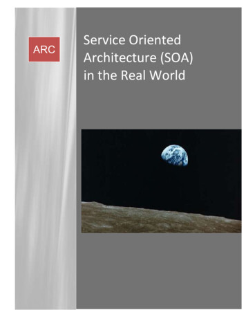
developerWorks ibm.com/developerWorksonto an existing RUP work product: The design model. Figure 1 attempts to illustratehow this mapping works.Figure 1. Mapping the external system model to the design modelUsing Figure 1 as reference, we define the following about the external systemmodel: It captures, at a design level, a representation of non-service-orientedsoftware that forms a part of the solution. The software that it covers can include both software that is new to thebusiness (for example, new packages that are being purchased andrequire integration), as well as existing software used by the business(commonly known as legacy software), although the focus is still onnon-service-oriented software. Its purpose is to capture the form and constraints of software that isexternal to but that is integrated into service-oriented software systems. As it maps to the design model, we it is "owned" by the RUP Analysis andDesign discipline. The owning role is the designer who would create or source (get) most ofthe model during the Inception phase in a RUP-based project. We say"create or source" because the designer may be either leveraging existingmodel elements and diagrams or creating new ones. We include the external system model as one of the work productscreated as part of the bottom-up track of the meet-in-the-middleapproach.The service model is a design-level model, as well. When the distinction is madebetween a service model and a design model, the service model will contain thespecification of the design at a higher level of abstraction and use only SOAelements (service provider, service, service consumer, service specification, forexample). The design model then acts as a detailed design model and contains bothSOA and non-SOA artifacts.External system modelingPage 4 of 21 Copyright IBM Corporation 1994, 2008. All rights reserved.
ibm.com/developerWorksdeveloperWorks In practical terms, the external system model can be seen either as a set ofpackages within the design model containing the information, as scoped in Figure 1,or as totally separate from the design model but at the same level of abstraction.Note:We use the word system as it is defined in the Rational Unified Process (seeResources for more information): "A collection of connected units that are organizedto accomplish a specific purpose." Wherever we use the word system, you canpotentially replace it with sub-system, solution, application, composite application, orbusiness application.Bottom-up analysis in an SOA or integration projectIn SOA, the bottom-up approach is about analyzing existing IT assets (such aslegacy applications and systems) and finding functionality that could be exposed asservices to be reused for many purposes. For example, the bottom-up approachanalyzes existing Information Management System (IMS) transactions or COBOLprograms.Reuse is an important part of SOA and critical to its success. As you probably know,your legacy applications (that is, those that have already been deployed) are yourcompany's most valuable assets, thus it is important to take advantage of themwhenever and however you can.Note:IBM offers methods, techniques, and engagement models specifically for "legacy toSOA transformation." Also, using existing asset-analysis tools, such as IBMWebSphere Studio Asset Analyzer, is critical, because, often, nobody knows exactlywhat is deployed and running! However, this is not the subject of this article. Here,we just want to show how you would capture the results of a bottom-up approach byusing Rational Software Architect.The bottom-up approach is used on integration projects where some software needsto be integrated into the overall solution and this software has not been designedand built as service-oriented software. By that, we mean software where the parts ofthe architecture were not specifically designed as interacting service consumers andservice providers. This involves more than just simply adding services onto yoursoftware parts. Specifically, a service-oriented solution needs its logic factored insuch a way that its individual parts can be integrated into a number ofservice-oriented systems.Bottom-up analysis is all about investigating the external form of the software that isbeing integrated into your solution, so that you have a clear understanding of twokey things: The functionality provided by that software Any constraints that this places on the solutionExternal system modeling Copyright IBM Corporation 1994, 2008. All rights reserved.Page 5 of 21
developerWorks ibm.com/developerWorksThis analysis work is done during the RUP Inception phase for integration projects,because this information may have an important bearing on the cost and schedule ofthe project.A handful of examples: You may discover that there is software that needs to be integrated intothe solution that has considerable complexity in its exposed API(application programming interface). There may be functionality that needs to be integrated that was notapparent from the top-down work (in other words, from looking at thebusiness processes). In engaging with system specialists for these external systems, you maydiscover that there are changes being made to their exposed APIs thatwill affect the timelines of your own project. There might be duplication of data between systems that will need to beaddressed by the architecture of the solution. Where external systems are being provided by third parties and these arenew to the organization, the bottom-up analysis might challengehigh-level statements made by the third party about the accessibility,completeness, and versioning stability of the API exposed by theirsystem.Important:It is crucial that the "unknown" risks associated with integrating with an externalsystem are mitigated during Inception, before budgets and time constraints areagreed upon for the project. Otherwise, there might be some nasty surprises instore!Section 3. Modeling external systems and theirinterfacesCreating an external systems model in Rational SoftwareArchitectThe starting point here is the SOA tutorial project that is the result of Part 2, whichcontains our domain model. Download the file (from the Downloads section here),and then follow these instructions to import the project into your workspace.Note:If you still have the workspace available from Part 2, skip these steps and proceed toExternal system modelingPage 6 of 21 Copyright IBM Corporation 1994, 2008. All rights reserved.
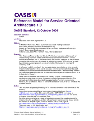
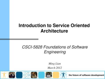
ibm.com/developerWorksdeveloperWorks Step 8.1.Start Rational Software Architect. Use the default workspace, or createa new one.2.After Rational Software Architect has launched, close the WelcomeScreen if you are in a new workspace.3.Select File Import.4.In the Import wizard, type project in the Select an import sourcefilter field, and then select Project Interchange and click Next (Figure 2).Figure 2. Import Project Interchange5.Click Browse and point to the location where you saved ip file.External system modeling Copyright IBM Corporation 1994, 2008. All rights reserved.Page 7 of 21
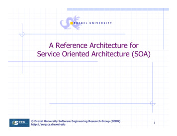
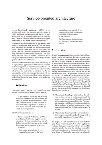
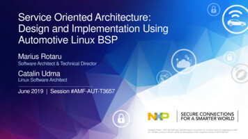
developerWorks 6.ibm.com/developerWorksSelect SOA Tutorial and click Finish (Figure 3).Figure 3. Import the SOA tutorial project7.Select Window Open Perspective Modeling to switch to theModeling perspective.8.Expand SOA Tutorial Models, and double-click Domain Model toopen it. Click OK if prompted by a Warning that referenced models arenot available.9.You should see something like Figure 4 in your Project Explorer view.Figure 4. Initial Project Explorer viewExternal system modelingPage 8 of 21 Copyright IBM Corporation 1994, 2008. All rights reserved.
ibm.com/developerWorksdeveloperWorks We will use a section of our design model as our external system model. So to startwith, you need to create a new UML model for the design model.10. Select the SOA Tutorial project. Right-click it, and then click New UMLModel.11. From the New UML Model dialog, leave the Standard template selectedand click Next.12. Enter Design Model as the file name, and deselect Create a defaultdiagram in the model.13. Click Finish.You will now have an empty design model in your SOA tutorial project.14. Select the Design Model, right-click it, and then click Add UML Package.15. Name it External Systems.16. Delete the Main diagram in this package by right-clicking on it, and thenclicking Delete from Model. This results in a new model, as shown inFigure 5.Figure 5. New external systems package (in the design model)External system modeling Copyright IBM Corporation 1994, 2008. All rights reserved.Page 9 of 21
developerWorks ibm.com/developerWorksIdentifying the external systemsNow we need to understand what external systems will be a part of our solution. Inmodeling the Return Video business process, we had noted that the Retrievemember's standing automated task needs to be done by integrating with an existingCustomer Relationship Management (CRM) system. Assume that your discussionwith the business process owner has resulted in you being put in touch with a seniordeveloper who is responsible for the CRM system. He has given you the followinginformation: The system is an off-the-shelf package that was purchased from a smallCRM vendor several years ago. The software runs on a .NET platform, but it has a Web services APIexposed. There are notes in a PDF document called "Integrating with the CRMSystem's API" provided with the software. It describes the form of theWeb services API, along with instructions about how to invoke it.This is good, because there should be enough information in the PDF document topopulate our external systems model. However this remains to be seen.1.Create a new package under External Systems for our CustomerRelationship Management system. Call it CustomerRelationshipMgt.2.Right-click on the package in the Project Explorer view, and select AddUML Subsystem. Name it CustomerRelationshipMgt also. (Makesure that you keep the subsystem stereotype when you rename it.)3.Rename the default diagram that was created in the package toCustomerRelationshipMgt ExternalSystemSpec.4.Make sure that the diagram is open, and drag the new subsystem onto it.The result of all this is as shown in Figure 6.Figure 6. The CustomerRelationshipMgt external systemNow we're ready to model our external system.External system modelingPage 10 of 21 Copyright IBM Corporation 1994, 2008. All rights reserved.
ibm.com/developerWorksdeveloperWorks Identifying the provided interfacesWhile reading the "Integrating with the CRM System's API" document, we find outthat the system has several Web service-based APIs, each of which exposes adifferent set of CRM-related functionality. However, we find a specific API called theCustomer Functions API that gives us access to the CRM information that werequire. Instead of modeling all of the exposed APIs, we will focus on just modelingthe API that we require. Based on the information in the document, we create aninterface for this API in our model:1.Create a package under the CustomerRelationshipMgt package. Nameit Provided Interfaces, and delete the default diagram.2.Create a package under the Provided Interfaces package. Name itCustomerFunctionsAPI. Rename the default diagram toCustomerFunctionsAPI InterfaceSpec.3.Right-click on the CustomerFunctionsAPI package, and then select AddUML Interface. Name it CustomerFunctionsAPI.4.The CustomerFunctionsAPI InterfaceSpec diagram should be open.Drag the new interface onto it.The diagram should appear as in Figure 7.Figure 7. The CustomerFunctionsAPI InterfaceSpec diagramWe'll look at detailing this interface later (note that, for this system, we have only aprovided interface --- there are no required interfaces). For now, we'll link it to ourexternal system spec:5.Open the CustomerRelationshipMgt ExternalSystemSpec diagram.6.Select the CustomerFunctionsAPI interface in the Project Explorerview, and drag it onto the diagram that we've just opened.7.From the Palette, find Realization under the Class section. Click on it,and then click on the CustomerRelationshipMgt subsystem on thediagram, and drag a realization to the CustomerFunctionsAPI that wasExternal system modeling Copyright IBM Corporation 1994, 2008. All rights reserved.Page 11 of 21
developerWorks ibm.com/developerWorksjust placed on the diagram.The diagram should now look like Figure 8.Figure 8. The CustomerRelationshipMgt ExternalSystemSpec diagramWe'll change the way this diagram appears now and add a link to the interface specdiagram:8.Right-click on CustomerRelationshipMgt, Filters Show ExternalView.The external view shows the provided interface using what is commonly called thelollipop (or lollypop) notation, because of the symbol.9.To remove the CustomerFunctionsAPI from the diagram, right-click on itfrom the diagram, and select Delete from diagram.10. Select the CustomerFunctionsAPI InterfaceSpec diagram from theProject Explorer view. Drag it onto the CustomerRelationshipMgtExternalSystemSpec diagram that we had open, so that you create adiagram shortcut.Tip:Adding diagram shortcuts makes the model easier to navigate. This is especiallyuseful when the models are published in HTML format.11. Click Note Attachment in the Palette (see Figure 9) and draw a noteattachment between the new diagram shortcut that we've created and thelollipop symbol representing the CustomerFunctionsAPI on theCustomerRelationshipMgt subsystem.Figure 9. Creating a note attachmentExternal system modelingPage 12 of 21 Copyright IBM Corporation 1994, 2008. All rights reserved.
ibm.com/developerWorksdeveloperWorks The diagram should now appear as in Figure 10.Figure 10. The finished CustomerRelationshipMgt ExternalSystemSpecdiagramSection 4. Modeling external system information andinterfacesAs we've learned earlier in Part 2, our domain model provides a structured view ofthe information that exists in the business domain. This is extremely useful whencommunicating internally within IT, as well as when IT needs to communicate aboutthe business. However it's important to note that, although the domain model willinfluence the form of the software solution, it is not modeling software directly.It is, however, useful to have a domain model-type view of the information that ismanaged by a specific system. Instead of structuring the terms (domain types) usedby the business, it will structure the terms used by the external system interfaces(provided and required). It will specifically focus on those types that are stored andmanaged by the external system.This domain model-type view is called an information model. We create anExternal system modeling Copyright IBM Corporation 1994, 2008. All rights reserved.Page 13 of 21
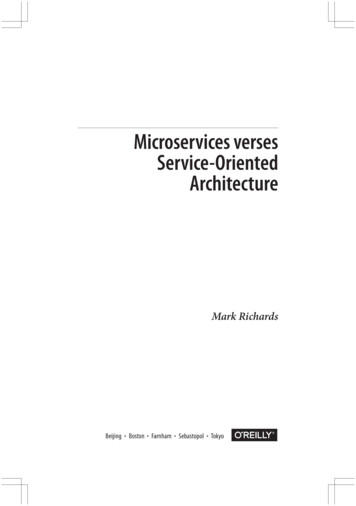
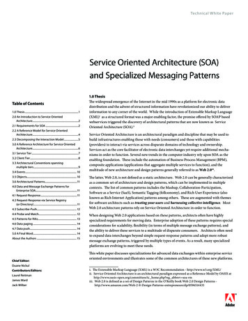
developerWorks ibm.com/developerWorksinformation model for each external system that persists some information (which ismost systems). (We can also use information models within our service model –more on that in a future part of this series.)Modeling the information viewAn information model looks very much like a domain model. The main difference isthat this model contains information types (info types) rather than domain types. Inmany respects, an info type looks exactly like a domain type. The difference is thatan info type describes a structured type of information that exists in a softwaredomain (external system or architectural part); whereas, a domain type describes astructured type of information that exists in a business domain.Looking at the "Integrating with the CRM System's API" document again, wediscover that the information types stored by the Customer RelationshipManagement system that is relevant to the Customer Functions API are customerand customer category. We also note a description of the attributes of both of thesetypes of information, along with a note that a customer is related to a singlecustomer category.Let's add this information to our model.1.Create a new package under the CustomerRelationshipMgt package.Name it Info Types.2.Delete the default diagram and create a new class diagram. Name itCustomerRelationshipMgt InfoTypes.3.Create the following model elements: An infoType Customer Class with the following attributes: customerId: String name: String address: String telephoneNumber: String [0.1] An infoType CustomerCategory with a name String attribute A * to [0.1] association between Customer and CustomerCategoryThe result is shown in Figure 11.If you need help doing this, check Part 2. Modeling the business domain, aboutcreating the domain model. Note that infoType is a keyword.Figure 11. CustomerRelationshipMgt InfoTypes diagramExternal system modelingPage 14 of 21 Copyright IBM Corporation 1994, 2008. All rights reserved.
ibm.com/developerWorksdeveloperWorks Although we haven't modeled any in this example, as with a domain model, aninformation model can have enumerations and constraints.The last thing we'll do with our info model is add a diagram shortcut to ourCustomerRelationshipMgt ExternalSystemSpec diagram (see Figure 12).Figure 12. Adding a diagram shortcut to the information modelDetailing the interfacesWhat we modeled in the previous subsection is a representation of the informationthat is persisted by the external system. We also need to flesh out the interfacespecification that we created earlier. We do this by detailing the operations that existon the interface. The operation's signature is expressed in terms of parameters and,optionally, a return type. These are based on a another kind of type: the parameterExternal system modeling Copyright IBM Corporation 1994, 2008. All rights reserved.Page 15 of 21
developerWorks ibm.com/developerWorkstype. Let's look at an example.Again looking at the "Integrating with the CRM System's API" document, we find adescription of the operations that the Web service provides. We'll add thisinformation to our model.1.Open the CustomerFunctionsAPI InterfaceSpec diagram.2.Right-click on the CustomerFunctionsAPI Add UML Operation. Name itretrieveCustomer.Let's first look at the operation's parameters.3.Click the retrieveCustomer operation.4.In the Parameters section of the Properties view, right-click in the emptylist, Insert New Parameter (Figure 13).Figure 13. Insert New Parameter5.Change Name to customerId, and set Type to String.We'll now change the diagram so that this information is shown.6.Right-click on CustomerFunctionsAPI in the diagram, and select Filters Show Signature.The CustomerFunctionsAPI InterfaceSpec should appear as in Figure 14.Figure 14. The retrieveCustomer operation with a parameter addedExternal system modelingPage 16 of 21 Copyright IBM Corporation 1994, 2008. All rights reserved.
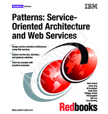
ibm.com/developerWorksdeveloperWorks We'll now define the return type of the operation. This will need to be based on aparameter type. Note that, in our example here, we use a parameter type for thereturn type. However, parameters can be described in terms of parameter typeswhere required.7.Create a new package under the CustomerRelationshipMgt package,and name it Parameter Types.8.Rename the default diagram to CustomerRelationshipMgtParameterTypes.9.Create a new class called Customer and add the parameterType keyword to it.10. Add attributes as shown below in Figure 15.Figure 15. The new parameter types package11. Open the CustomerFunctionsAPI InterfaceSpec diagram.12. Drag the Customer parameter type onto the diagram.13. Select the retrieveCustomer operation.14. In the General section of the Properties view, click Set return type.15. Set the return type to Customer, thereby ensuring that you select theCustomer parameter type that is owned by the CustomerRelationshipMgtexternal system.The diagram should now appear as in Figure 16.External system modeling Copyright IBM Corporation 1994, 2008. All rights reserved.Page 17 of 21
developerWorks ibm.com/developerWorksFigure 16. The retrieveCustomer operation with return type definedWe've now reached the point where we have a concrete view of the external systemthat we need to integrate (albeit a very simple example for this tutorial). We have afirm view of what the interface that we will be integrating with looks like, and we alsounderstand what information we are using from the system and how it is structured.Although this is quite a simple example, the same principles are essential whentackling larger external systems and managing their complexity.Section 5. What's nextIn this part of this tutorial series, we looked at the bottom-up track of the meet-in-themiddle approach, and, more specifically, the external non-SOA systems that are itsfocus. We discussed the importance of this activity in an SOA project, and then welooked, in detail, at how to create an external systems model by using RationalSoftware Architect. More specifically, we looked at modeling provided interfaces andinformation models. In the parts of this series that follow, we will get into the core ofSOA modeling: Creating the service model.External system modelingPage 18 of 21 Copyright IBM Corporation 1994, 2008. All rights reserved.
ibm.com/developerWorksdeveloperWorks DownloadsDescriptionNameSizeDownload erchange.zip9KBHTTPprojectDVD ge.zip13KBHTTPInformation about download methodsExternal system modeling Copyright IBM Corporation 1994, 2008. All rights reserved.Page 19 of 21
developerWorks ibm.com/developerWorksResourcesLearn Read Part 1 of this series, "Model Service-Oriented Architectures with RationalSoftware Architect: Part 1. Case study, tools, and the business view ". Read Part 2 of this series, "Model Service-Oriented Architectures with RationalSoftware Architect: Part 1. Case study, tools, and the business view ". A four part tutorial series by the same author: Design SOA services withRational Software Architect In the Pattern Solutions area on developerWorks, get the resources you need toadvance your skills in patterns-based development. Read the developerWorks introductory article, "The Rational UML profile forbusiness modeling" by Simon Johnston (April 2004). The Rational UML profilefor Business Modeling is a component of the Rational Unified Process (RUP). Itpresents a UML language for capturing business models and is supported bythe Business Modeling Discipline in the RUP. Read the developerWorks intermediate-level article, "Business servicesmodeling, Integrating WebSphere Business Modeler and Rational SoftwareModeler" by Jim Amsden (December 2005). Business Services Modeling formsthe foundation for the integration between IBM WebSphere Business Modeler,Rational Software Architect (and UML), and the Rational Unified Process (RUP)business modeling guidelines to better support model-driven development(MDD). Visit the Rational software area on developerWorks for technical resources andbest practices for Rational Software Delivery Platform products. In particular,visit the Rational Software Architect area. Subscribe to the developerWorks Rational zone newsletter. Keep up withdeveloperWorks Rational content. Every other week, you'll receive updates onthe latest technical resources and best practices for the Rational SoftwareDelivery Platform. Browse the technology bookstore for books on these and other technical topics.Get products and technologies Download a trial version of Rational Software Architect. Download trial versions of IBM Rational software. Download IBM product evaluation versions and get your hands on applicationdevelopment tools and middleware products from DB2 , Lotus , Rational ,Tivoli , and WebSphere .Discuss Rational Software Architect, Data Architect, Software Modeler, ApplicationDeveloper and Web Developer forum: Ask questions about Rational SoftwareExternal system modelingPage 20 of 21 Copyright IBM Corporation 1994, 2008. All rights reserved.
ibm.com/developerWorksdeveloperWorks Architect. Check out developerWorks blogs and get involved in the developerWorkscommunity.About the authorsGregory HodgkinsonGregory Hodgkinson is founder, director, and the SOA lead at 7irene, an IBM Tier 1Business Partner in the United Kingdom (www.7irene.com). He has 10 years ofexperience in software architecture, initially specializing in the field ofcomponent-based development (CBD), then moving seamlessly into servi
Models: Demonstrate how the Rational Software Architect supports a model-driven development (MDD) approach to the specification of service-oriented architectures. After describing software architecture and defining the place of services within it, this series then introduces Rational Software Architect a