Transcription
1111 Canfield Avenue Randolph, New Jersey 07869 1-800-LANDICE FAX 973-927-06308700-SeriesHome and Commercial TreadmillDiagnostic and Service Manual2001This guide covers all 8700 series treadmills manufactured from1993 – 2000.HOME TREADMILLS – 8700 SPRINT 1-4 / PRG / SSTNOTE: Early HOME treadmills listed as: 8700R & 8700P are the same as the LTD models.The only difference was the warranty coverage.LTD / 110V UNITS – 8700R (REGILAR NO PROGRAMS) / P (WITH PROGRAMS) / PT1 / PT2CLUB / 220V UNITS – 8700R (REGILAR NO PROGRAMS) / P (WITH PROGRAMS) / PT1 / PT2Version M/C.1For Technical Service Call 1-(800)-LANDICE
2Service Manual Ver M/C.1Page 2Table of ContentsSECTION 1- IntroductionPage 3How to use this manualPage 4-5Landice warranty and policyPage 6Tools needed for repairsSECTION 2- InstallationPage 7-9Safety warningsPage 10-13 Membrane panel identificationSECTION 3- - Parts IdentificationPage 14-16 Parts listingPage 17Commercial motor pan picturePage 18Commercial (LTD / CLUB) motor pan lower wiring schematicPage 19-20 LED lights / SCR lower boardPage 21Home motor pan picturePage 22Home motor pan wiring schematicPage 23LED lights / PWM boardPage 24LED lights / RELAY boardPage 25SST, PRG, SPRINT-3 (Open Loop); lower wiring schematicPage 26SPRINT – 2; lower wiring schematicPage 27SPRINT – 1; lower wiring schematicPage 28SPRINT – 1&2; upper wiring schematicSECTION 4 –Servicing Landice TreadmillsPage 29-31 Definitions of componentsPage 32-34 Testing componentsPage 35-37 Common symptomsPage 38Calibrating speed potentiometersPage 39-45 Removal and replacement of componentsPage 46-48 NoisesPage 49Voltage checksPage 50Diagnostics and error codesPage 51-59 8700 LTD / CLUB diagnostic flow chartsPage 60-65 8700 HOME (Closed Loop / SPRINT-4, SST, PRG) diagnostic flow chartsPage 66-68 SPRINT –3 DiagnosticsPage 69-75 SPRINT –2 DiagnosticsPage 76-77 Tracking and TensioningPage 78-79 Treadmill maintenancePage 80-84 Index
3How to Use this ManualThis manual is designed to help service technicians in the installation, maintenance, or repair ofLandice 8700 model treadmills. It covers terminology, installation, tools needed, diagnostics, removaland replacement of parts, estimated time of repairs, warranty forms, wiring schematics, andrecommended maintenance. If you find a problem not covered in this manual please call 1-800LANDICE to talk to a Landice Service Technician.
4Landice Warranty and PoliciesPARTSOur policy requires that all defective parts be returned to Landice. All warranty partswill be billed to the dealer at dealer cost. Landice will credit this invoice upon receiptof defective parts. Landice will pay the freight to send out any defective parts. It is thedealer's responsibility to pay the freight to return the defective parts to Landice. If thedefective parts are not returned within 30 days, payment of invoice is expected in full.LABORLandice will reimburse the selling dealer according to our flat rate labor schedule. Ifyou are a service provider for Landice and do not sell our product, you have the optionof billing us direct or you can bill the dealer your providing service for. Generally, if ourcapped rate does not cover your labor charge you would bill the selling dealer. Thecurrent rate is 30.00 per hour and is capped at a maximum of one hour labor andone hour travel per treadmill failure. Diagnosticand return trips are not covered. Note that treadbelt tracking, treadbelt/drivebelttensioning, blown fuses, and set-up procedures are not covered by this warranty.Set-Up Includes: Assembly, adjusting treadbelt and drive belt (if needed), walkingthe treadbelt and deck wax in and performing any additional adjustments that mayhave been upset during shipping.The dealer must call for a service authorization number prior to performing any serviceto verify the treadmill is under labor warranty. It is advisable to call Landice from thetreadmill location to successfully diagnose the problem. This will ensure that thecorrect part will be shipped out the first time. Labor claim forms must be submittedwithin three months from the date service was performed. Labor claim forms must becompletely filled out and have the Landice authorization number at the top.FLOOR MODELSThe following warranty applies to floor models and dealer stock.If the dealer sells a treadmill to a customer within one year of its purchase fromLandice, the warranty period will be extended to start from the date of sale to thecustomer.If a treadmill is over 1 year old when sold to a customer, the remainder of the partswarranty will be honored from the date of shipment and 1 year labor.
5September 1, 2001Treadmill Warranty SummaryLandice Factory Warranty SummaryHome Treadmills07-15-199807-15-199607-15-1993Lifetime FrameLifetime FrameLifetime Frame5 Year Parts3 Year Parts2 Year Parts1 Year Labor1 Year Labor1 Year Labor8700LTD Limited Institutional Use Treadmills (120VAC)(In applications with under 5 hours usage per day)09-01-199609-01-19933 Years Parts1 Year Parts1 Year Labor1 Year Labor8700 CLUB Treadmills (220VAC)11-15-199611-15-1993(Scheduled maintenance required)3 Years Parts1 Year Labor1 Year Parts1 Year LaborTREADMILL PARTSAll defective parts must be delivered to Landice (freight prepaid) where they will either be repaired orreplaced at Landice's discretion. This warranty does not cover cosmetic damage, damage due to actsof God, accident, misuse, abuse, improper maintenance, or negligence to the product. This warrantydoes cover normal wear and tear. This warranty is valid only in the United States and Canada.SERVICE LABORFor a period of 1 year, Landice will reimburse the selling dealer according to the terms, rates andconditions in effect at the time of service. A service authorization number must be obtained prior toperforming service in order to qualify for service reimbursement. This service warranty does not covercustomer instruction, installation, setup, or adjustments. Note that treadbelt tensioning and tracking isthe responsibility of the user and is not covered by this warranty. Instructions for treadbelt tensioningand tracking are located in the owner's manual. This warranty is valid only in the United States andCanada.
6Recommended tools for servicing Landice treadmills1. Deep socket set 3/8 drive with ratchet and extension: Must have 3/8, 7/16, 1 /2, 5/16, 9/16 socket.2. Combination wrench set: Must have 3/8, 7/16, 1 /2, 5/16, 9/163. #1, 2, and 3 Philips head screwdriver (or electric screwdriver)4. #1, 2, and 3 flat head screwdriver (or electric screwdriver)5. Socket head cap screw wrench set/ multi Allen Wrench6. Rubber mallet7. Diagonal cutting pliers8. Wire stripper9. Wire crimping tool10. Digital voltmeter (We recommend Radio Shack Pocket Digital Voltmeter). Analog voltmeters arenot recommended.11. Utility knife12. Pulse simulator
7Important Operating Safety InstructionsWARNING: Failure to observe the following operating instructions can result in seriousinjury!1If you are suffering from any illness, condition, or disability which affects your ability torun, walk or exercise, do not use this product without consulting your doctor first.2If you are suffering from any illness, condition, or disability which affects your ability torun, walk or exercise, do not use this product without supervision present. Failure to doso can result in serious injury should you fall while the treadbelt is moving.3Failure to leave ample clearance around the treadmill could result in the user becomingtrapped between the treadmill and a wall, resulting in burns or other serious injury fromthe moving treadbelt.Allow a minimum clearance of 18 inches on each side of the treadmill.Allow a minimum clearance of 4 feet at the rear of the treadmill.4Never stand on the treadbelt when starting the treadmill. A sudden start could cause youto lose your balance. Always stand with one foot on each side rail until the belt startsmoving.5Always wear the emergency stop safety strap securely around your wrist whileexercising. Failure to do so can result in severe injuries should you accidentally fall whileexercising.6Test the emergency stop safety key on a regular basis by pulling on the cord andensuring that the treadbelt comes to a complete stop.7Always remove the safety key from the treadmill when you are through exercising,especially if children are present. This will prevent them from accidentally starting thetreadmill.8Be sure to familiarize yourself with the owner manual. Look it over carefully. Be sure youunderstand the control panel operation before using the treadmill.
8DANGERTo reduce the risk of electric shock, always unplug the treadmill from the electrical outletimmediately after using. Always unplug the treadmill before cleaning or removing themotor cover.WARNINGTo reduce the risk of burns, fire, electric shock, or injury to persons:1234Treadmill should never be left unattended when plugged in. Unplug from outlet when notin use.Close supervision is necessary when this unit is used by or near children or disabledpersons.Use this treadmill only for its intended use as described in this manual.Do not operate this treadmill if it has a damaged cord or plug, if it is not working properly or if ithas been damaged. Call your selling dealer immediately for examination and repair.5Keep the power cord away from heated surfaces. Be sure the line cord has plenty ofslack and does not get pinched underneath the treadmill when it elevates and lowers. Ifan extension cord must be used do not use one longer than 6 feet with 12 gauge wire.6Never operate the treadmill with the air openings blocked. Keep the air openings free oflint, hair, and the like.7Never drop or insert any object into any opening. Be sure no objects are near orunderneath the moving treadbelt when using the treadmill.8Do not use outdoors.9Do not operate where aerosol spray products are being used or where oxygen is beingadministered.10 Connect this appliance to a properly grounded outlet only. Do not use a GFI outlet.11 To disconnect, press the OFF button, remove the SAFETY LANYARD, and unplug theunit from the wall outlet.GROUNDING INSTRUCTIONSThis product must be grounded. If it should malfunction or break down, grounding provides apath of least resistance for electric current to reduce risk of electric shock. This product isequipped with a cord having an equipment-grounding conductor and a grounding plug. Theplug must be plugged into an outlet that is properly installed and grounded in accordance withall local codes and ordinances. We do not recommend using a GFI outlet.120 Volt Treadmills (15 Amp dedicated line)Treadmills marked 120 VAC are intended for use in a nominal 120-volt circuit with agrounding plug. Make sure the product is connected to an outlet having the sameconfiguration as the plug. No adapter should be used with this product.
9200 - 250 Volt Treadmills (15 Amp dedicated line)Treadmills marked 200-250 VAC are intended for use on a circuit having a nominal ratingmore than 120V and are factory-equipped with a specific cord and plug to permit connectionto a proper electric circuit. Make sure the product is connected to an outlet having the sameconfiguration as the plug. No adapter should be used with this product. If the product mustbe reconnected for use on a different type of electric circuit, the reconnection should be madeby qualified service personnel.DANGER! Improper connection of the equipment-grounding connector can result in a risk ofelectric shock. Check with a qualified electrician or serviceman if you are in doubt as towhether the product is properly grounded. Do not modify the plug provided with the product.If it will not fit in the outlet, have a proper outlet installed by a qualified electrician.
108700 Standard MembraneModels That Used This Membrane: 8700, 8700-R, 8700-LTD, 8700-LTD-VFX,8700-CLUB, 8700-CLUB-VFXProduction Time Frame: 1991-1999Electronics: Standard 110V SCR (220V SCR for CLUB units), commercial motor pan.See Wiring Diagram.Settings Used In: Home and Commercial (LTD’s and CLUB’s)Key Features: Closed Loop Treadmill (w/ speed sensor), Safety Lanyard, 0.5-11MPH Push ButtonSpeed and Elevation Control8700 Sprint MembraneModels That Used This Membrane: 8700 Sprint-1, 8700 Sprint-2Production Time Frame: Sprint-1 1991-1995, Sprint-2 1995-1996Electronics: 110V Unit, See Wiring Diagrams for 8700 Sprint-1 and Sprint-2Settings Used In: HomeKey Features: Open Loop Treadmill (w/o speed sensor), Safety Lanyard on Sprint-2 only, 1.09.0MPH Rheostat Speed Control, Rocker Switch Elevation Control.
118700 EP/PT MembraneModels That Used This Membrane: 8700EP, 8700-PTProduction Time Frame: 1991-1993Electronics: Standard 110V SCR (220V SCR for CLUB units), commercial motor pan.See Wiring Diagram.Settings Used In: Home and CommercialKey Features: Closed Loop Treadmill (w/ Speed sensor) Safety Lanyard, 0.5-11.0MPH Push ButtonSpeed and Elevation Control, 10 Built In Programs, 4 User Programs, Wireless Heart Rate Control(Optional), LED Graphic Display.8700 P MembraneModels That Used This Membrane: 8700-P, 8700-LTD-P, 8700-CLUB-PProduction Time Frame: 1991-1999Electronics: Standard 110V SCR (220V SCR for CLUB units), commercial motor pan.See Wiring Diagram.Settings Used In: Home and Commercial (LTD’s and CLUB’s)Key Features: Closed Loop Treadmill (w/ speed sensor), Safety Lanyard, 0.5-11MPH Push ButtonSpeed and Elevation Control, 5 Built In Programs.
128700 PT2 MembraneModels That Used This Membrane: 8700-PT2, 8700-CLUB-PT2Production Time Frame: 1994-1998Electronics: Standard 110V SCR (220V SCR for CLUB units), commercial motor pan.See Wiring Diagram.Settings Used In: Home and CommercialKey Features: Closed Loop Treadmill (w/ Speed sensor) Safety Lanyard, 0.5-11.0MPH Push ButtonSpeed and Elevation Control, 9 Built In Programs, 4 User Programs, Wireless Heart Rate Control,SONAR ranging capability (Optional), LED Graphic Display.8700 SST MembraneModels That Used This Membrane: 8700-SST, 8700-SST-VFXProduction Time Frame: 1995-1999Electronics: 8700-SST used Sprint-3 electronics, 8700-SST-VFX used Sprint-4 electronics,See Wiring Diagrams.Settings Used In: HomeKey Features: 8700-SST Open Loop Treadmill (w/o speed sensor), 8700-SST-VFX Closed LoopTreadmill (w/ Speed sensor) Safety Lanyard, 0.5-12.0MPH Push Button Speed and Elevation Control.5 Built In Programs, 5 User Programs, Wireless Heart Rate Control, SONAR ranging capability.
138700 Programmable MembraneModels That Used This Membrane: 8700-PRG, 8700-PRG-VFX, 8700-CLUB-PRGProduction Time Frame: 1996-1999Electronics: 8700-PRG used Sprint-3 electronics, 8700-PRG-VFX used Sprint-4 electronics,8700-CLUB-PRG used 220V PWM commercial motor pan. See Wiring Diagrams.Settings Used In: Home and Commercial (LTD’s and CLUB’s)Key Features: Closed Loop Treadmill (w/ speed sensor), Safety Lanyard, 0.5-12MPH Push ButtonSpeed and Elevation Control, 4 Built In Programs, 2 User Programs.8700 Sprint FaceplateModels That Used This Faceplate: 8700 Sprint-3, 8700 Sprint-4, 8700-Sprint-4-VFXProduction Time Frame: Sprint-3 1997-1998, Sprint-4 1998-1999Electronics: 110V Unit, See Wiring Diagrams for 8700 Sprint-3 and Sprint-4Settings Used In: HomeKey Features: Sprint-3 Open Loop Treadmill (w/o speed sensor), Sprint-4 Closed Loop Treadmill (w/Speed sensor) Safety Lanyard, 0.5-12.0MPH Push Button Speed and Elevation Control.
14Section 3 – Parts IdentificationModel 8700 Treadmill PartsItemTreadbeltTreadbelt - XLSlider Deck (Non-VFX)Slider Deck - XL (Non-VFX)VFX DeckVFX Deck SpacerVFX Deck SlatVFX Deck PostVFX Deck Load WasherVFX Deck, Flet WasherVFX Deck, Impact AdjusterDrive Motor, 3 HP, 110VFlywheelMotor BracketTension ScrewMetal SpacerRubber SpacerHitch PinDrive BeltMotor Brush, 110VMotor Brush HolderMotor Brush CapFoam BlockElevation AssemblyElevation Motor, 110VElevation PotentiometerElevation PinsElevation NutElevation ClevisBearing BlockPanPWM 110VRELAY Board, PWMNylon Spacer, # 8 ScrewReading Rack ClearDisplay Board - 8700PRG (Closed Loop)Display Board - 8700SST (Closed Loop)Display Board - SPRINT4 (Closed Loop)Display Board - SPRINT - MetricDisplay Board - SPRINT -7 MphSONAR Transducer W/ cableSONAR Ranging BoardSONAR P 326.00 381.00 208.75 258.35 200.00 9.00 25.05 5.00 3.40 2.50 0.20 584.50 75.15 59.70 2.50 1.89 1.65 0.42 25.05 15.53 58.16 7.11 8.35 181.02 275.00 32.72 2.83 25.05 17.28 14.00 150.00 280.50 100.50 0.25 35.00 518.00 541.08 275.00 285.00 285.00 60.15 100.20 8.75Note2 per tread3 per tread6 per tread6 per tread6 per tread6 per treadmust order w/ 700103 per tread2 per tread2 per tread2 per tread2 per tread
15Membrane Panel - SPRINT3/4Membrane Panel - 8700PRGMembrane Panel - SSTMembrane Panel - NMA (CRT,PRT)Velcro CircleVelcro StripDrive Roller AssemblySheave, Frt RollerTake Up Roller AssemblyDC Transformer, 9V 110VControl Panel FrameControl Panel W/ Sonar HoleBracket SonarUpright, LeftUpright, RightStablizer PlateControl Panel End Cap, RightControl Panel End Cap , LeftFrame Rail , LeftFrame Rail, RightDecal, Frame, RightDecale, Frame, LeftSide FrameTop CoverHarness, SPRINT4 UpperHarness, SPRINT4 LowerIsolation TransformerSupression kitAxi Shock Supension FOOTFoot Clamp (Solid foot)Motor Cover Grey8700 Landice name plateMotor Cover , Fire Retardant BlackMotor Cover, Clear8-32 x 3/4 PPHTT BL OXSpeed SensorSpeed Sensor BracketLine Cord, with 5-15P PlugPlug, 5-15P, Hospital Grade (110V)Strain ReliefFuse, 110VFuse 2970008700447020970044-FR70044-CLEAR8-32 3/4 TTB710077006752115-15PHGP1250MDA-20MDA-HOLDER 167.00 225.45 225.45 210.42 0.85 5.00 215.75 20.04 200.40 24.63 114.90 116.90 5.00 116.57 116.57 25.00 8.52 8.52 215.17 215.17 22.45 22.45 51.35 30.00 15.05 429.50 17.00 60.00 15.00 158.65 8.25 242.15 317.30 0.75 58.50 3.76 48.26 33.00 0.58 2.51 3.25must order w/ CV-18-2Right or Leftmust order w/70209 (no charge)screw for motor cover
16Wireless Pulse Option "Pulse Kit"Extender KitReceiver KitPulse Belt/TransmitterPulse ReceiverExtender CableRight Angle AdapterIsolation Leakage OptionIsolation Leakage Option Dealer InstalledTraction StripCover, Side FrameSIDE FRAME XLSide RailRail ClampCross BarCross Bar FoamHardware KitMedical RailFoam Medical & Runners RailInstallation Charge, Optional 85MISC 167.00 25.05 125.25 108.55 100.20 16.70 8.35 167.00 20.00 11.41 51.35 190.00 53.44 33.57 25.05 must order w/1858 7.55 25.05 104.38 must order w/70185 8.35 108.55Spacer, Rail SupportEnd CapWheelNMA StickerSafety Lanyard8700SPRINT User's Manual8700PRG User's Manual8700SST User's ManualInstitutional BrochuresHome BrochuresQuality Construction 7020072017 5.01 12.53 6.68 1.67 15.50 8.35 8.35 8.35Touch Up PaintSlipcote Lubricant 1oz PacketSlipcote Lubricant QUARTSlipcote Lubricant GALLONApplicator7022471037710307103171016 25.05 1.50 35.00 96.00 4.002 per tread4 cans/save 4.0016cans/save 39.00
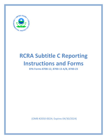
178700 COMERCIAL MOTOR PAN COMPONENTS
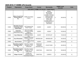
188700 COMMERCIAL LOWER WIRING SCHEMATIC
19LED (light emitting diode) configurations: SCR lower boardThe SCR lower board is designed with diagnostic LED lights. The LED’s are color coded according totheir specific function. Green indicates a properly operating treadmill; the green lights should alwaysbe ON when power is supplied to the treadmill. Yellow indicates a treadmill function. Red indicates atreadmill malfunction. Here is a list of each LED and what it signifies:MOTOR (yellow) – The MOTOR LED illuminates when dc (direct current) voltage is sent to the drivemotor. The LED gets brighter when the dc output is increased.RLC (yellow) – The RLC (R Reactance / L Inductance / C Capacitance) LED illuminates whenthe filtering system is properly working. The filtering system includes the capacitor and filter choke. Ifthere is a short in either component then the RLC light will not come on.DN & UP (yellow) – The DN and UP LED lights tell us if the elevation DN and UP relays arefunctioning properly. When the LED lights, it tells us that the relay has energized and is sending highvoltage (110vac or 220vac) to the elevation motor.AC PWR (green) – The AC PWR (Alternating Current Power) illuminates when AC line voltage isdelivered to the treadmill. It then passes through the in-line fuse (110)/s(220) and lights the AC PWRLED. 12V (green) – When the proper AC voltage is delivered to the treadmill, passes through the in-linefuse/s, through the full wave bridge rectifier (changes AC to DC), through the transformer (steps downDC to 12vdc) then the 12V LED lights.
20C. LIM (red) – The C.LIM or Current Limit LED should NEVER come on. This diagnostic light is usedto determine the condition of the treadbelt and deck. The SCR board has a built-in amp meter. Whenthe treadbelt belt and deck system wears, the amperage will increase. When this amperage reachesits max limit, the lower board will shut down its power (treadbelt will slow down / low torque) to thedrive motor and the C.LIM LED will illuminate.SPD (yellow) – The SPD LED flashes on and off (relative to speed) when the speed sensor isoperating properly.GRD (red) – The GRD LED should NEVER come on. It illuminates only when the elevationpotentiometer becomes out of calibration.SERIAL (red) – The SERIAL LED should NEVER come on. It illuminates only when there is a serialerror. This could be a loose or pushed pin on the main wire harness. 5V (green) – The 5V light comes on when there is power going to the Upper Display. If the light isnot on check wire harness for connections. If it ‘s not the wire harness then the MCB is defective.
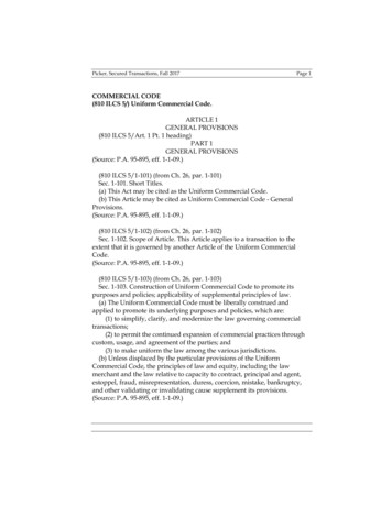
218700 HOME SST VFX, PRG VFX, SPRINT VFXCLOSED LOOP (SPEED SENSOR)
228700 SST, PRG and SPRINT VFX TREADMILLAll VFX treadmills utilize CLOSED LOOP speed control.All treadmills listed as VFX in the warranty database use a speed sensor.
23LED LIGHTS ON PWMThe PWM lower board is designed with two diagnostic LED lights. The LED’s are color codedaccording to their specific function.LED 1 (red) – This indicates a high current draw similar to the C.LIM LED on our SCR lower controlboard. LED 1 will only light if there is high current being used due to a possible worn out treadbelt anddeck system or it can also light if the IR pot is out of adjustment. The IR pot controls how the PWMboard reacts to varying loads (users’ weights). If the IR pot is out of adjustment you will notice thetreadbelt will surge and the red LED 1 will flash in unison with the belt surge.LED 2 (green) – This indicates proper line voltage is being supplied to the PWM board. This linevoltage is delivered to the PWM via the belt relay located on the relay board. When the belt relayenergizes 110VAC or 220VAC is sent to the input terminals (L1 & L2) on the PWM board and LED 1illuminates.
24LED (light emitting diode) configurations: RELAY BOARDThe RELAY board is designed with diagnostic LED lights. The LED’s are color coded according totheir specific function. Green indicates a properly operating treadmill; the green lights should alwaysbe ON when power is supplied to the treadmill. Yellow indicates a treadmill function. Red indicates atreadmill malfunction. Here is a list of each LED and what it signifies:AC PWR (green) - The AC PWR (Alternating Current Power) illuminates when AC line voltage isdelivered to the treadmill. It then passes through the in-line fuse (110)/s(220) and lights the AC PWRLED.VDC (green) – The VDC LED will light when it receives DC voltage from the DC power supply.DN & UP (yellow) – The DN and UP LED lights tell us if the elevation DN and UP relays arefunctioning properly. When the LED lights, it tells us that the relay has energized and is sending highvoltage (110vac or 220vac) to the elevation motor.UPSW (green) – This LED will illuminate when the low voltage dc is delivered from the upper displayboard to the elevation UP relay. This low voltage dc is what energizes the coil of the relay.DNSW (green) - This LED will illuminate when the low voltage dc is delivered from the upper displayboard to the elevation DOWN relay. This low voltage dc is what energizes the coil of the relay.BELTSW (green) - This LED will illuminate when the low voltage dc is delivered from the upperdisplay board to the belt (motor start) relay. This low voltage dc is what energizes the coil of the relay.SPD (yellow) – The SPD LED flashes on and off (relative to speed) when the speed sensor isoperating properly.PWM (yellow) – This LED will light when the upper board is sending a speed signal to the PWM.Both the PWM LED and BELTSW LED must be lit for belt movement.
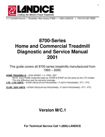
258700 SST, PRG and SPRINT 3, NON VFX TREADMILLAll NON VFX treadmills utilize OPEN LOOP speed control and no relay boards.Sprint 3 treadmills have push button controls
268700 SPRINT 2Safety lanyard, speed control dial (not push button), KBWT-110 SCR motor control
278700 SPRINT 1 – LOWER WIRING SCHEMATICNO safety key, speed control dial (not push button), KBLC-118 Motor Control Board
288700 SPRINT 1&2 UPPER WIRING SCHEMATIC
29Section 4- Servicing Landice TreadmillsDefinitions12 VDC POWER SUPPLY (Transformer)This transformer converts AC power to DC power. It provides low voltage current for the upperdisplay board. This component is found on treadmills with PWM motor control boards. It isincorporated into the SCR motor control boards.CAPACITORStores energy to smooth out voltage to drive motor. Used with SCR motor control boards.CHOKE (Inductor)Acts like a filter to smooth out voltage to drive motor. Used with SCR motor control boards.DECKWooden board 1” thick with a phenolic coating. Treadbelt rides over it. It is reversible.DRIVE BELTThis connects drive motor to sheave (pulley) on drive roller.DRIVE MOTORProvides power to drive belt to turn pulley on drive roller to move treadbelt. This gets its power fromthe PWM or SCR. Landice drive motors are either 110v for 220v.DRIVE ROLLER W/ SHEAVEThis is the roller at the front of the treadmill. The sheave (pulley) is pressed onto the roller and allowstransfer of movement from drive belt to treadbelt.ELEVATION LEG ASSEMBLYConnects to elevation motor to allow movement of front of treadmill up or down.ELEVATION MOTORThis motor works through the elevation leg assembly to raise or lower the front of the treadmill. It getsits power from the relay board on home models and from the SCR on LTD and CLUB models.ELEVATION POTENTIOMETERAttaches to elevation motor and gives feedback to upper display as to what incline the treadmill is at.Needs to be calibrated whenever elevation motor is replaced. A potentiometer should be checkedwhenever there is a problem with elevation or when error code PO comes up.FACE PLATEThis overlay is found on our Sports Trainer, Pro Sports Trainer, and CRT models and is screwed ontothe Upper Display Board.SIDE FRAMESOne on either side, these connect with the Deck Slats and Motor Pan to form the frame of themachine.
30SIDE FRAME COVERSThese sit on top of the frame rails and keep deck in place. They also form the base for the tractionstrip.IR POTENTIOMETERThe IR Pot is located on the PWM motor control board and is used to adjust the time it takes thePWM to react to a load or amperage spike. It normally requires adjustment if the motor feels like itssurging.MEMBRANE PANELThis takes information from the display membrane keys and transmits it to upper display board via theribbon cable. It is found on the PT, CT, and ET models.PWM (Pulse Width Modulation) Motor Control Boards- Used in home models.This circuit board is designed to run the drive motor. It takes the AC voltage from the wall outlet andchanges it to DC voltage to run the drive motor. The AC voltage comes in on the L1 line and L2 lineterminals on the PWM where it’s rectified (change from AC to DC) and comes out as DC on terminalsA and A- (Armature and Armature -). Since the PWM motor control switches at such a highfrequency, the DC voltage produced is “clean” and relatively free of electrical noise or static. In otherwords, it needs no external Capacitor or Choke (Inductor) to run the drive motor. It receives itscommands from the Upper Display Board via the Relay Board. Generally these need the voltagecoming out of the outlet to be or – 8 % of the PWM rating. For example a 115v PWM should haveoutlet voltage of at least 106v with a maximum of 124v.RELAY BOARDSThis circuit board controls the elevation relays, belt relays, DC transformer (for Upper Display Power),and diagnostic lights. It is only found on mills with PWM Motor Control Boards.SAFETY LANYARDThis is a safety feature that completes a switch in the display board. If it is not connected the treadmillwill not run.SCR (Silicon Controlled Rectifier) Motor Control Boards-Used in LTD (110v) and Club Models (220v)This circuit board is designed to run the drive motor, elevation relays, the belt relay, DC transformerfor power to Upper Display Board, and on board diagnostic lights. The SCR requires a Capacitor andChoke to provide “clean” power to the Drive Motor. It receives its commands from the Upper DisplayBoard and eliminates the need for a Relay Board. These require outlet voltage of or – 10% of theSCR rating.SLIPCOTE LUBRICANTRecommended treadbelt lubricant for Landice commercial treadmills.SPEED SENSORLandice uses a magnetic speed sensor to receive accurate speed readings. Readings are takendirectly from the flywheel on the motor and sent to the Relay Board or SCR. Distance between thesensor and the flywheel is critical but the senso
3 Failure to leave ample clearance around the treadmill could result in the user becoming trapped between the treadmill and a wall, resulting in burns or other serious injury from the moving treadbelt. Allow a minimum clearance of 18 inches on each side of the treadmill. Allow a minimum clearance of 4 feet at the rear of the treadmill.