Transcription
Maintenance and ServiceGuideHP Pavilion dv6000 Notebook PCDocument Part Number: 416618-003April 2007This guide is a troubleshooting reference used for maintainingand servicing the computer. It provides comprehensiveinformation on identifying computer features, components, andspare parts; troubleshooting computer problems; and performingcomputer disassembly procedures.
Copyright 2006, 2007 Hewlett-Packard Development Company, L.P.Microsoft, Windows and Windows Vista are either trademarks or registeredtrademarks. Intel, Core, and Celeron are trademarks or registeredtrademarks of Intel Corporation or its subsidiaries in the United States andother countries and regions. Bluetooth is a trademark owned by itsproprietor and used by Hewlett-Packard Company under license. SD Logois a trademark of its proprietor. AMD, the AMD Arrow logo andcombinations thereof are trademarks of Advanced Micro Devices, Inc.The information contained herein is subject to change without notice. Theonly warranties for HP products and services are set forth in the expresswarranty statements accompanying such products and services. Nothingherein should be construed as constituting an additional warranty. HP shallnot be liable for technical or editorial errors or omissions contained herein.Maintenance and Service GuideHP Pavilion dv6000 Notebook PCThird Edition: April 2007First Edition: August 2006Document Part Number: 416618-003
Safety warning noticeÅWARNING: To reduce the possibility of heat-related injuries or ofoverheating the computer, do not place the computer directly on yourlap or obstruct the computer air vents. Use the computer only on a hard,flat surface. Do not allow another hard surface, such as an adjoiningoptional printer, or a soft surface, such as pillows or rugs or clothing, toblock airflow. Also, do not allow the AC adapter to contact the skin or asoft surface, such as pillows or rugs or clothing, during operation. Thecomputer and the AC adapter comply with the user-accessible surfacetemperature limits defined by the International Standard for Safety ofInformation Technology Equipment (IEC 60950).
Contents1 Product Description1.11.21.31.41.5Features . . . . . . . . . . . . . . . . . . . . . . . . . . . . . . . . . . . 1–2Resett ing the Computer . . . . . . . . . . . . . . . . . . . . . . 1–4Power Management. . . . . . . . . . . . . . . . . . . . . . . . . . 1–5External Components . . . . . . . . . . . . . . . . . . . . . . . . 1–6Design overview . . . . . . . . . . . . . . . . . . . . . . . . . . . 1–212 Troubleshooting2.1 Setup Utility in Windows XP . . . . . . . . . . . . . . . . . . 2–1Using the Setup Utility . . . . . . . . . . . . . . . . . . . . . . . 2–1Setup Utility Menus . . . . . . . . . . . . . . . . . . . . . . . . . 2–52.2 Setup Utility in Windows Vista . . . . . . . . . . . . . . . . 2–8Using the Setup Utility . . . . . . . . . . . . . . . . . . . . . . . 2–8Setup Utility Menus . . . . . . . . . . . . . . . . . . . . . . . . 2–112.3 Troubleshooting Flowcharts . . . . . . . . . . . . . . . . . . 2–15Maintenance and Service Guidev
Contents3 Illustrated Parts Catalog3.13.23.33.43.53.63.7Serial Number Location . . . . . . . . . . . . . . . . . . . . . . 3–1Computer Major Components. . . . . . . . . . . . . . . . . . 3–2Display Assembly Components . . . . . . . . . . . . . . . 3–22Mass Storage Devices . . . . . . . . . . . . . . . . . . . . . . . 3–24Plastics Kit . . . . . . . . . . . . . . . . . . . . . . . . . . . . . . . 3–26Miscellaneous . . . . . . . . . . . . . . . . . . . . . . . . . . . . . 3–28Sequential Part Number Listing . . . . . . . . . . . . . . . 3–314 Removal and Replacement Preliminaries4.1 Tools Required . . . . . . . . . . . . . . . . . . . . . . . . . . . . .4.2 Service Considerations . . . . . . . . . . . . . . . . . . . . . . .Plastic Parts . . . . . . . . . . . . . . . . . . . . . . . . . . . . . . . .Cables and Connectors . . . . . . . . . . . . . . . . . . . . . . .4.3 Preventing Damage to Removable Drives . . . . . . . .4.4 Preventing Electrostatic Damage . . . . . . . . . . . . . . .4.5 Packaging and Transporting Precautions . . . . . . . . .4.6 Workstation Precautions . . . . . . . . . . . . . . . . . . . . . .4.7 Grounding Equipment and Methods . . . . . . . . . . . . intenance and Service Guide
Contents5 Removal and Replacement Procedures5.1 Serial Number . . . . . . . . . . . . . . . . . . . . . . . . . . . . . . 5–25.2 Disassembly Sequence Chart . . . . . . . . . . . . . . . . . . 5–35.3 Preparing the Computer For Disassembly . . . . . . . . 5–55.4 Hard Drive. . . . . . . . . . . . . . . . . . . . . . . . . . . . . . . . . 5–75.5 Computer Feet. . . . . . . . . . . . . . . . . . . . . . . . . . . . . 5–115.6 Memory Module . . . . . . . . . . . . . . . . . . . . . . . . . . . 5–125.7 RTC Battery . . . . . . . . . . . . . . . . . . . . . . . . . . . . . . 5–155.8 Mini Card Module. . . . . . . . . . . . . . . . . . . . . . . . . . 5–165.9 Optical Drive. . . . . . . . . . . . . . . . . . . . . . . . . . . . . . 5–215.10 Switch Cover. . . . . . . . . . . . . . . . . . . . . . . . . . . . . 5–235.11 Keyboard . . . . . . . . . . . . . . . . . . . . . . . . . . . . . . . . 5–265.12 Speaker Assembly. . . . . . . . . . . . . . . . . . . . . . . . . 5–305.13 Power Button Board . . . . . . . . . . . . . . . . . . . . . . . 5–315.14 Display Assembly . . . . . . . . . . . . . . . . . . . . . . . . . 5–335.15 Top Cover . . . . . . . . . . . . . . . . . . . . . . . . . . . . . . . 5–465.16 Audio Board . . . . . . . . . . . . . . . . . . . . . . . . . . . . . 5–525.17 Bluetooth Module . . . . . . . . . . . . . . . . . . . . . . . . . 5–545.18 ExpressCard Assembly . . . . . . . . . . . . . . . . . . . . . 5–565.19 USB/Power Connector Board . . . . . . . . . . . . . . . . 5–595.20 System Board . . . . . . . . . . . . . . . . . . . . . . . . . . . . 5–615.21 Fan/Heat Sink Assembly. . . . . . . . . . . . . . . . . . . . 5–665.22 Processor . . . . . . . . . . . . . . . . . . . . . . . . . . . . . . . . 5–69Maintenance and Service Guidevii
Contents6 SpecificationsA Screw ListingB Backup and Recovery in Windows XPC Backup and Recovery in Windows VistaD Display Component RecyclingE Connector Pin AssignmentsF Power Cord Set RequirementsIndexviiiMaintenance and Service Guide
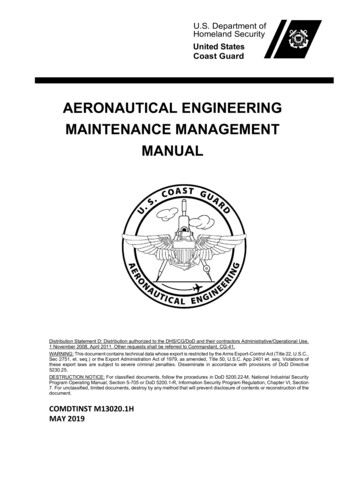
1Product DescriptionThe HP Pavilion dv6000 Notebook PC offers advancedmodularity, Intel Core Duo and Celeron and AMDTurion 64 Mobile Technology and Mobile AMD Sempron processors, and extensive multimedia support.HP Pavilion dv6000 Notebook PCMaintenance and Service Guide1–1
Product Description1.1 Features The following processors are available, varying bycomputer model: Intel Core Duo T7200 (2.00-GHz) Intel Core Duo T1350 (1.86-GHz) Intel Core Duo T5600 (1.83-GHz) Intel Core Duo T2350 (1.86-GHz) Intel Core Duo T2250 (1.73-GHz) Intel Core Duo T5500 (1.66-GHz) Intel Core Duo T5200 (1.66-GHz) Intel Core Duo T2060 (1.60-GHz) Intel Core Duo T2300E (1.66-GHz) Intel Core Duo T2050 (1.60-GHz) Intel Celeron 440 (1.86-GHz) Intel Celeron 430 (1.73-GHz) Intel Celeron 420 (1.60-GHz) AMD Turion ML-60 2.0-GHz AMD Turion ML-56 1.8-GHz AMD Turion ML-52 1.6-GHz AMD Turion ML-50 1.6-GHz Mobile AMD Sempron 3500 (1.8-GHz) Mobile AMD Sempron 3400 (1.8-GHz) Mobile AMD Sempron 3200 (1.6-GHz) 15.4-inch WXGA (1280 768) TFT display with over16.7 million colors, varying by computer model 200-, 160-, 120-, 100-, 80-, 60-, or 40-GB high-capacity harddrive, varying by computer model 256-MB DDR synchronous DRAM (SDRAM) at 667 MHz,expandable to 2.0 GB1–2Maintenance and Service Guide
Product Description Microsoft Windows Vista Business, Windows VistaHome Basic, and Windows XP ProfessionalFull-size Windows keyboard with embedded numeric keypadTouchPad pointing device with on/off button and dedicatedtwo-way scroll zoneIntegrated 10/100 BASE-T Ethernet local area network(LAN) network interface card (NIC) with RJ-45 jackIntegrated high-speed 56K modem with RJ-11 jackIntegrated wireless support for Mini Card IEEE 802.11b and802.11b/g WLAN deviceSupport for ExpressCardExternal 90- or 65-watt AC adapter with 3-wire power cord6-cell or 12-cell Li-Ion batteryStereo speakers with volume up and down buttonsIntegrated microphones (select models only)Support for the following optical drives: DVD RW/R and CD-RW Double-Layer Combo Drivewith LightScribe DVD RW/R and CD-RW Double-Layer Combo Drive DVD/CD-RW Combo DriveConnectors: Audio-in (microphone) Audio-out (headphone) Consumer infrared lens Docking (select models only) ExpressCard External monitor IEEE 1394 digital (select models only) Digital Media Slot (select models only) PowerMaintenance and Service Guide1–3
Product Description RJ-11 (modem) RJ-45 (network) S-Video-out (select models only) Universal Serial Bus (USB) v. 2.01.2 Resetting the ComputerIf the computer you are servicing has an unknown password,follow these steps to clear the password. These steps alsoclear CMOS:1. Prepare the computer for disassembly (refer to Section 5.3,“Preparing the Computer For Disassembly,” for moreinformation).2. Remove the real-time clock (RTC) battery (refer toSection 5.7, “RTC Battery,” for more information).3. Wait approximately 5 minutes.4. Replace the RTC battery and reassemble the computer.5. Connect AC power to the computer. Do not reinsert anybatteries at this time.6. Turn on the computer.All passwords and all CMOS settings have been cleared.1–4Maintenance and Service Guide
Product Description1.3 Power ManagementThe computer comes with power management features thatextend battery operating time and conserve power. Thecomputer supports the following power management features: Standby Hibernation Setting customization by the user Hotkeys for setting the level of performance Battery calibration Lid switch standby/resume Power button Advanced Configuration and Power Management (ACPM)complianceMaintenance and Service Guide1–5
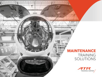
Product Description1.4 External ComponentsThe external components on the front of the computer are shownbelow and described in Table 1-1.Front ComponentsTable 1-1Front ComponentsItemComponentFunction1Power lightOn: The computer is on.Blinking: The computer is in standby.Off: The computer is off or in hibernation.2Battery lightOn: A battery is charging.Blinking: A battery that is the only availablepower source has reached a low-batterycondition. When the battery reaches acritical low-battery condition, the batterylight begins blinking rapidly.Off: If the computer is plugged into anexternal power source, the light is turned offwhen all batteries in the computer are fullycharged. If the computer is not plugged intoan external power source, the light stays offuntil the battery reaches a low-batterycondition.1–6Maintenance and Service Guide
Product DescriptionTable 1-1Front Components (Continued)ItemComponentFunction3Drive lightBlinking: The hard drive or optical drive isbeing accessed.4Wireless switchTurns the wireless feature on or off, butdoes not create a wireless connection.wireless network must be set up to Aestablisha wireless connection.5Wireless lightBlue: An integrated wireless device, suchas a wireless local area network (LAN)device and/or a Bluetooth device, isturned on.Amber: All wireless devices are turned off.6Consumer infraredlens (select modelsonly)Receives a signal from the HP RemoteControl.7Audio-in(microphone) jackConnects an optional computer headsetmicrophone, stereo array microphone, ormonaural microphone.8Audio-out(headphone) jackProvides sound when connected to optionalpowered stereo speakers, headphones,ear buds, a headset, or television audio.Audio-out(headphone) S/PDIFjack (select modelsonly)Provides enhanced audio performance,including surround sound and otherhigh-end audio output.Maintenance and Service Guide1–7
Product DescriptionThe external components on the left side of the computer areshown below and described in Table 1-2.Left-Side ComponentsTable 1-2Left-Side ComponentsItemComponentFunction1Security cable slotAttaches an optional security cable to thecomputer.security cable is designed to act Theas a deterrent, but it may not preventthe computer from being mishandledor stolen.2S-Video-out jackConnects an optional S-Video device suchas a television, VCR, camcorder, overheadprojector, or video capture card.3External monitor portConnects an external VGA monitor orprojector.1–8Maintenance and Service Guide
Product DescriptionTable 1-2Left-Side Components (Continued)ItemComponentFunction4Expansion port 3Connects the computer to an optionalexpansion product.computer has only one Theexpansion port. The term expansionport 3 describes the type ofexpansion port.5RJ-45 (network) jackConnects a network cable.select computer models, the Onnetwork jack provides GigabitEthernet functionality.6RJ-11 (modem) jackConnects a modem cable.7HDMI port(select models only)Connects an optional audio or video devicesuch as a high definition television, set-topbox, DVD player, or any compatible digitalor audio device.8USB ports (2)Connect optional USB devices.91394 port (selectmodels only)Connects an optional IEEE 1394 or 1394adevice, such as a camcorder.10Digital Media Slot(select models only)Supports the following optional digital cardformats: Secure Digital (SD) Memory Card,MultiMediaCard (MMC), Secure DigitalInput/Output (SD I/O), Memory Stick (MS),Memory Stick Pro (MSP), xDPicture Card(XD), xD-Picture Card (XD) Type M.Maintenance and Service Guide1–9
Product DescriptionThe external components on the right side of the computerare shown below and described in Table 1-3.Right-Side ComponentsTable 1-3Right-Side ComponentsItemComponentFunction1ExpressCard slotSupports optional ExpressCard/54 cards.2Optical driveReads an optical disc.3USB port(select models only)Connects an optional USB device.4Power connectorConnects an AC adapter.1–10Maintenance and Service Guide
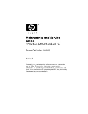
Product DescriptionThe computer keyboard components are shown below anddescribed in Table 1-4.Keyboard ComponentsMaintenance and Service Guide1–11
Product DescriptionTable 1-4Keyboard ComponentsItemComponentFunction1Function keysExecute frequently used system functionswhen pressed in combination with thefn key.2caps lock keyEnables caps lock and turns on the capslock light.3fn keyExecutes frequently used systemfunctions when pressed in combinationwith a function key or the esc key.4Windows logo keyDisplays the Microsoft Windows Startmenu.5Windowsapplications keyDisplays a shortcut menu for itemsbeneath the pointer.6Arrow keysMove the cursor around the screen.7Embedded numerickeypad keysCan be used like the keys on an externalnumeric keypad.8num lock keyEnables numeric lock, turns on theembedded numeric keypad, and turnson the num lock light.1–12Maintenance and Service Guide
Product DescriptionThe computer top components are shown below and described inTable 1-5.Top Components, Part 1Maintenance and Service Guide1–13
Product DescriptionTable 1-5Top Components, Part 1ItemComponentFunction1Integrated camera(select models only)Records video and captures still photos.2Internal microphones(2, select models only)Record sound.microphone icon next to each Amicrophoneopening indicates thatthe computer has internalmicrophones.3Speakers (2)Produce sound.4Power buttonWhen the computer is Off, press to turn on the computer.On, press to enter hibernation.In standby, briefly press to exit standby.In hibernation, briefly press toexit hibernation.If the computer has stopped respondingand Microsoft Windows shutdownprocedures cannot be used, press and holdthe power button for at least 5 seconds toturn off the computer.5Caps lock lightOn: Caps lock is on.6Volume mute buttonMutes and restores speaker sound.7Volume scroll zoneAdjusts speaker volume. Slide your fingerto the left to decrease volume and to theright to increase volume. You can also tapthe minus sign on the scroll zone todecrease volume, or tap the plus sign onthe scroll zone to increase volume.8Num lock lightOn: Num lock is on or the embeddednumeric keypad is enabled.1–14Maintenance and Service Guide
Product DescriptionThe computer top components are shown below and described inTable 1-6.Top Components, Part 2Maintenance and Service Guide1–15
Product DescriptionTable 1-6Top Components, Part 2ItemComponentFunction1Media buttonIf QuickPlay is not installed and thecomputer is On, opens the music program or Mediamenu, which allows you to select amultimedia program. Off, does not function. In standby, resumes from standby intoWindows.If QuickPlay is installed and the computer is On, opens the music program or Mediamenu, which allows you to select amultimedia program. Off, opens the music program or theMedia menu, which allows you to selecta multimedia program. In standby, resumes from standby intoWindows.media button does not affect the Theprocedure for restoring fromhibernation.2DVD buttonWhen the computer isopens the default DVD program On,to start a DVD in the optical drive.opens QuickPlay to start a DVD Off,in the optical drive. If the QuickPlaysoftware is not installed, the DVDbutton starts in Windows.opens QuickPlay to Instarthibernation,a DVD in the optical drive. IfQuickPlay is not installed, thecomputer resumes from hibernation.1–16Maintenance and Service Guide
Product DescriptionTable 1-6Top Components, Part 2 ttonWhen a disc is playing in the optical drive: Plays the previous track or chapter,when pressed once. Rewinds when pressed with the fn key.4Play/pause buttonWhen a disc is in the optical drive and is Not playing, plays the disc. Playing, pauses the disc.5Next/fast forwardbuttonWhen a disc is playing in the optical drive: Play the next track or chapter, whenpressed once. Fast forwards when pressed with thefn key.6Stop buttonWhen a disc is playing in the optical drive,stops the current disc activity.Maintenance and Service Guide1–17
Product DescriptionThe computer TouchPad components are shown below anddescribed in Table 1-7.TouchPad ComponentsTable 1-7Touchpad ComponentsItemComponentFunction1TouchPad lightBlue: TouchPad is enabled.Amber: TouchPad is disabled.2TouchPadMoves the pointer and selects or activatesitems on the screen.3Left and rightTouchPad buttonsFunction like the left and right buttons on anexternal mouse.4TouchPad on/offbuttonEnables/disables the TouchPad.5TouchPad verticalscroll zoneScrolls up or down.1–18Maintenance and Service Guide
Product DescriptionThe external components on the bottom of the computerare shown below and described in Table 1-8.Bottom ComponentsTable 1-8Bottom ComponentsItemComponentFunction1Battery bayHolds the battery.2Battery release latchReleases the battery from thebattery bay.3Optical driveReads an optical disc.Maintenance and Service Guide1–19
Product DescriptionTable 1-8Bottom Components (Continued)ItemComponentFunction4Memory modulecompartmentContains the memory module slots, theMini Card slot, and the RTC battery.5Vents (5)Enable airflow to cool internalcomponents.computer fan starts up Theautomatically to cool internalcomponents and preventoverheating. It is normal for theinternal fan to cycle on and offduring routine operation.61–20Hard drive bayHolds the hard drive.Maintenance and Service Guide
Product Description1.5 Design overviewThis section presents a design overview of key parts and featuresof the computer. Refer to Chapter 3, “Illustrated Parts Catalog,”to identify replacement parts, and Chapter 5, “Removal andReplacement Procedures,” for disassembly steps.The system board provides the following device connections:Ä AMD Turion and Mobile AMD Sempron processors Audio Display ExpressCard Fan Hard drive Intel Core Duo and Celeron processors Keyboard and TouchPad Memory module Mini Card moduleCAUTION: To properly ventilate the computer, allow at least a 7.6-cm(3-inch) clearance on the left and right sides of the computer.The computer uses an electric fan for ventilation. The fan iscontrolled by a temperature sensor and is designed to turn onautomatically when high temperature conditions exist. Theseconditions are affected by high external temperatures, systempower consumption, power management/battery conservationconfigurations, battery fast charging, and software. Exhaust air isdisplaced through the ventilation grill located on the left side ofthe computer.Maintenance and Service Guide1–21
2TroubleshootingÅWARNING: Only authorized technicians trained by HP should repairthis equipment. All troubleshooting and repair procedures are detailedto allow only subassembly-/module-level repair. Because of thecomplexity of the individual boards and subassemblies, do not attemptto make repairs at the component level or modifications to any printedwiring board. Improper repairs can create a safety hazard. Anyindication of component replacement or printed wiring boardmodification may void any warranty or exchange allowances.2.1 Setup Utility in Windows XPThe Setup Utility is a ROM-based information and customizationutility that can be used even when your Windows operatingsystem is not working or will not load.The utility reports information about the computer and providessettings for startup, security, and other preferences.1. Turn on or restart the computer in Windows.2. Before Windows opens and while the “Press F10 to entersetup” prompt is displayed in the lower-left corner of thescreen, press f10.Using the Setup UtilityChanging the Language of the Setup UtilityThe following procedure explains how to change the language ofthe Setup Utility. If the computer is not in the Setup Utility, beginat step 1. If the computer is in the Setup Utility, begin at step 2.Maintenance and Service Guide2–1
Troubleshooting1. To open the Setup Utility, turn on or restart the computer inWindows, and then press f10 while the prompt, “Press F10 to enter setup,” is displayed in the lower-left corner of thescreen.2. Use the arrow keys to select System Configuration Language, and then press enter.3. Press f5 or f6 (or use the arrow keys) to select a language, andthen press enter to select a language.4. When a confirmation prompt with your preference selectedis displayed, press enter to save your preference.5. To set your preferences and exit the Setup Utility, press f10and then follow the instructions on the screen.Your preferences go into effect when the computer restarts inWindows.Navigating and Selecting in the Setup UtilityBecause the Setup Utility is not Windows-based, it does notsupport the TouchPad. Navigation and selection are by keystroke. To choose a menu or a menu item, use the arrow keys. To choose an item in a drop-down list or to toggle a field,for example an Enable/Disable field, use either the arrowkeys or f5 or f6. To select an item, press enter. To close a text box or return to the menu display, press f1. To display additional navigation and selection informationwhile the Setup Utility is open, press f1.Displaying System InformationThe following procedure explains how to display systeminformation in the Setup Utility. If the Setup Utility is not open,begin at step 1. If the Setup Utility is open, begin at step 2.2–2Maintenance and Service Guide
Troubleshooting1. To start the Setup Utility, turn on or restart the computer inWindows, and then press f10 while the prompt, “Press F10 to enter setup,” is displayed in the lower-left corner of thescreen.2. Access the system information by using the Main menu.3. To close the Setup Utility without changing any settings, usethe arrow keys to select Exit Exit Discarding Changes,and then press enter. (The computer restarts in Windows.)Restoring Default Settings in the Setup UtilityThe following procedure explains how to restore the Setup Utilitydefault settings. If the computer is not in the Setup Utility, beginat step 1. If the computer is in the Setup Utility, begin at step 2.1. To start the Setup Utility, turn on or restart the computer inWindows, and then press f10 while the prompt, “Press F10 to enter setup,” is displayed in the lower-left corner of thescreen.2. Select Exit Load Setup Defaults, and then press f10.3. When the Setup Confirmation is displayed, press enter to saveyour preferences.4. To set your preferences and exit the Setup Utility, press f10,and then follow the instructions on the screen.The Setup Utility default settings are set when you exit theSetup Utility and go into effect when the computer restarts.password, security, and language settings are not changed Yourwhen you restore the factory default settings.Maintenance and Service Guide2–3
TroubleshootingUsing Advanced Setup Utility FeaturesThis guide describes the Setup Utility features recommended forall users. For more information about the Setup Utility featuresrecommended for advanced users only, refer to the Help andSupport Center, which is accessible only when the computer is inWindows.The Setup Utility features available for advanced users include ahard drive self-test, a Network Service Boot, and settings for bootorder preferences.The “ F12 to boot from LAN” message that is displayed in thelower-left corner of the screen each time the computer is startedor restarted in Windows or restored from hibernation is theprompt for a Network Service Boot.The “Press ESC to change boot order” message that isdisplayed in the lower-left corner of the screen each time thecomputer is started or restarted in Windows or restored fromhibernation is the prompt to change the boot order.Closing the Setup UtilityYou can close the Setup Utility with or without saving changes. To close the Setup Utility and save your changes from thecurrent session, use either of the following procedures: Press f10, and then follow the instructions on the screen.– or – If the Setup Utility menus are not visible, press esc toreturn to the menu display. Then use the arrow keys toselect Exit Exit Saving Changes, and then press enter.When you use the f10 procedure, you are offered an optionto return to the Setup Utility. When you use the ExitSaving Changes procedure, the Setup Utility closes whenyou press enter.2–4Maintenance and Service Guide
Troubleshooting To close the Setup Utility without saving your changes fromthe current session:If the Setup Utility menus are not visible, press esc to returnto the menu display. Then use the arrow keys to select Exit Exit Discarding Changes, and then press enter.After the Setup Utility closes, the computer restarts in Windows.Setup Utility MenusThe menu tables in this section provide an overview of SetupUtility options.of the Setup Utility menu listed in this chapter may not Somebe supported by your computer.Main MenuTable 2-1Main MenuSelectTo Do ThisSystem Information Maintenance and Service GuideView and change the system time and date.View identification information about thecomputer.View specification information about theprocessor, memory size, system BIOS, andkeyboard controller version (select modelsonly).2–5
TroubleshootingSecurity MenuTable 2-2Security MenuSelectTo Do ThisAdministrator passwordEnter, change, or delete an administratorpassword.Power-on passwordEnter, change, or delete a power-on password.System Configuration MenuTable 2-3System Configuration MenuSelectTo Do ThisLanguage SupportChange the Setup Utility language.Embedded WLAN DeviceRadioEnable/disable an embedded wireless LANdevice.Embedded BluetoothDevice (select models only)Enable/disable an embedded Bluetooth device(select models only).Enhanced SATA support(select models only)Enable/disable enhanced SATA mode.2–6Maintenance and Service Guide
TroubleshootingTable 2-3System Configuration Menu (Continued)SelectTo Do ThisBoot OptionsSet the following boot options:f10 and f12 Delay (sec.)—Set the delay for thef10 and f12 functions of the Setup Utility inintervals of 5 seconds each (0, 5, 10, 15, 20). CD-ROM boot—Enable/disable boot fromCD-ROM. Floppy boot—Enable/disable boot from Floppy. Internal Network Adapter boot—Enable/disableboot from Internal Network Adapter. Boot Order—Set the boot order for: USB Floppy ATAPI CD/DVD ROM Drive Hard drive USB Diskette on Key USB Hard drive Network adapter Diagnostics MenuTable 2-4Diagnostics MenuSelectTo Do ThisHard Disk Self TestRun a comprehensive self-test on the hard drive.Maintenance and Service Guide2–7
Troubleshooting2.2 Setup Utility in Windows VistaThe Setup Utility is a ROM-based information and customizationutility that can be used even when your Windows operatingsystem is not working or will not load.fingerprint reader (select models only) does not work Thewhen accessing the Setup Utility.The utility reports information about the computer and providessettings for startup, security, and other preferences.To start the Setup Utility:1. Turn on or restart the computer.2. Before Windows opens and while “Press F10 to entersetup” is displayed in the lower-left corner of the screen,press f10.Using the Setup UtilityChanging the Language of the Setup UtilityThe following procedure explains how to change the language ofthe Setup Utility. If the Setup Utility is not already running, beginat step 1. If the Setup Utility is already running, begin at step 2.1. To start the Setup Utility, turn on or restart the computer, andthen press f10 while “Press F10 to enter setup” is displayedin the lower-left corner of the screen.2. Use the arrow keys to select System Configuration Language, and then press enter.3. Press f5 or f6 (or use the arrow keys) to select a language, andthen press enter to select a language.4. When a confirmation prompt with your preference selectedis displayed, press enter to save your preference.2–8Maintenance and Service Guide
Troubleshooting5. To set your preferences and exit the Setup Utility, press f10and then follow the instructions on the screen.Your pref
Guide HP Pavilion dv6000 Notebook PC Document Part Number: 416618-003 April 2007 This guide is a troubleshooting reference used for maintaining and servicing the computer. It provides comprehensive information on identifying computer features, components, and spare parts; troubleshooting computer problems;