Transcription
CISCO VALIDATED DESIGNCisco SD-WANDesign GuideOctober 2018
Table of ContentsTable of ContentsSD-WAN definition. 1Why deploy SD-WAN. 2Solution architecture overview. 3Components.3Color.5Virtual Private Networks (VPNs).6TLOC extension.7Bringing the vEdge into the overlay. 10Bootstrapping the vEdge router. 11Zero-Touch Provisioning (ZTP) process. 11Controller connections. 13Additional NAT considerations. 14Configuration templates. 15Device templates. 15Feature templates. 17Configuring parameters. 18Deploying device templates. 19Policies. 19Configuring localized policy. 20Configuring centralized policy. 21Order of operations. 22Traffic symmetry for DPI. 23Quality of Service (QoS) . 25Deployment planning. 27Port numbering. 27System IP. 27Site ID. 27Cisco Validated Design
SD-WAN definitionSD-WAN definitionThe enterprise landscape is continuously evolving. There is a greater demand for mobile and Internet-ofThings (IoT) device traffic, SaaS applications, and cloud adoption. In addition, security needs are increasing andapplications are requiring prioritization and optimization, and as this complexity grows, there is a push to reducecosts and operating expenses. High availability and scale continue to be important.Legacy WAN architectures are facing major challenges under this evolving landscape. Legacy WAN architecturestypically consist of multiple MPLS transports, or an MPLS paired with an Internet or LTE used in an active/backup fashion, most often with Internet or software-as-a-service (SaaS) traffic being backhauled to a centraldata center or regional hub for Internet access. Issues with these architectures include insufficient bandwidthalong with high bandwidth costs, application downtime, poor SaaS performance, complex operations, complexworkflows for cloud connectivity, long deployment times and policy changes, limited application visibility, anddifficulty in securing the network.In recent years, software-defined wide-area networking (SD-WAN) solutions have evolved to address thesechallenges. SD-WAN is part of a broader technology of software-defined networking (SDN). SDN is a centralizedapproach to network management which abstracts away the underlying network infrastructure from itsapplications. This de-coupling of data plane forwarding and control plane allows you to centralize the intelligenceof the network and allows for more network automation, operations simplification, and centralized provisioning,monitoring, and troubleshooting. SD-WAN applies these principles of SDN to the WAN.Cisco Validated Designpage 1
Why deploy SD-WANWhy deploy SD-WANThe Cisco SD-WAN solution is an enterprise-grade WAN architecture overlay that enables digital and cloudtransformation for enterprises. It fully integrates routing, security, centralized policy, and orchestration into largescale networks. It is multi-tenant, cloud-delivered, highly-automated, secure, scalable, and application-awarewith rich analytics. The Cisco SD-WAN technology addresses the problems and challenges of common WANdeployments. Some of the benefits include: Centralized management and policy management, as well as operational simplicity, resulting in reducedchange control and deployment times. A mix of MPLS and low-cost broadband or any combination of transports in an active/active fashion,optimizing capacity and reducing bandwidth costs. A transport-independent overlay that extends to the data center, branch, or cloud. Deployment flexibility. Due to the separation of the control plane and data plane, controllers can be deployedon premises or in the cloud, or a combination of either. Cisco vEdge router deployment can be physical orvirtual and can be deployed anywhere in the network. Robust and comprehensive security, which includes strong encryption of data, end-to-end networksegmentation, router and controller certificate identity with a zero-trust security model, control planeprotection, application firewall, and insertion of Cisco Umbrella , firewalls, and other network services. Seamless connectivity to the public cloud and movement of the WAN edge to the branch. Application visibility and recognition and application-aware policies with real-time service-level agreement(SLA) enforcement. Dynamic optimization of SaaS applications, resulting in improved application performance for users. Rich analytics with visibility into applications and infrastructure, which enables rapid troubleshooting andassists in forecasting and analysis for effective resource planning.Cisco Validated Designpage 2
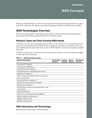
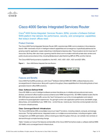
Solution architecture overviewSolution architecture overviewThe Cisco SD-WAN solution is comprised of separate orchestration, management, control, and data planes. The orchestration plane assists in the automatic onboarding of the SD-WAN routers into the SD-WAN overlay. The management plane is responsible for central configuration and monitoring. The control plane builds and maintains the network topology and makes decisions on where traffic flows. The data plane is responsible for forwarding packets based on decisions from the control plane.Figure 1. Overview of Cisco SD-WAN solution planesvManagevBondvSmartOrchestration planeManagementvBondAPIManagement plane(Multi-tenant or dedicated)AnalyticsOrchestrationvEdgeControl plane(Containers or VMs)ControlINETMPLS4GSecure ControlChannelData plane(Physical or Virtual)Data CenterCampusBranchHome OfficeComponentsThe primary components for the Cisco SD-WAN solution consist of the vManage network management system(management plane), the vSmart controller (control plane), the vBond orchestrator (orchestration plane), and thevEdge router (data plane). vManage - This centralized network management system provides a GUI interface to easily monitor,configure, and maintain all Cisco SD-WAN devices and links in the underlay and overlay network. vSmart controller - This software-based component is responsible for the centralized control plane of theSD-WAN network. It establishes a secure connection to each vEdge router and distributes routes and policyinformation via the Overlay Management Protocol (OMP), acting as a route reflector. It also orchestrates thesecure data plane connectivity between the vEdge routers by distributing crypto key information, allowing fora very scalable, IKE-less architecture.Cisco Validated Designpage 3
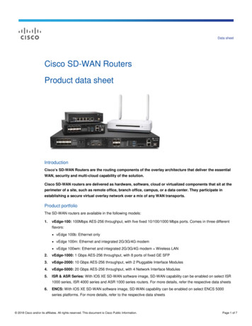
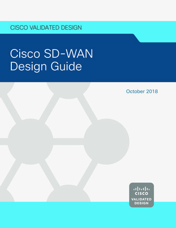
Solution architecture overview vBond orchestrator - This software-based component performs the initial authentication of vEdge devicesand orchestrates vSmart and vEdge connectivity. It also has an important role in enabling the communicationof devices that sit behind Network Address Translation (NAT). vEdge router - This device, available as either a hardware appliance or software-based router, sits at aphysical site or in the cloud and provides secure data plane connectivity among the sites over one or moreWAN transports. It is responsible for traffic forwarding, security, encryption, Quality of Service (QoS), routingprotocols such as Border Gateway Protocol (BGP) and Open Shortest Path First (OSPF), and more.The following diagram demonstrates several aspects of the Cisco SD-WAN solutionFigure 2. SD-WAN martvEdgepublicinternetThis sample topology depicts two sites and two public Internet transports. The SD-WAN controllers, the twovSmart controllers, and the vBond orchestrator, along with the vManage management GUI that reside on theInternet, are reachable through either transport.At each site, vEdge routers are used to directly connect to the available transports. Color is used to identify anindividual WAN transport; different WAN transports are assigned different colors, such as mpls, private1,biz-internet, metro-ethernet, lte, etc. The topology uses a color called biz-internet for one of the Internettransports and a color called public-internet for the other.The vEdge routers form a Datagram Transport Layer Security (DTLS) or Transport Layer Security (TLS) controlconnection to the vSmart controllers and connect to both of the vSmart controllers over each transport. ThevEdge routers securely connect to vEdge routers with IPSec tunnels at other sites over each transport. TheBidirectional Forwarding Detection (BFD) protocol is enabled by default and will run over each of these tunnels,detecting loss, latency, jitter, and path failures.Cisco Validated Designpage 4
Solution architecture overviewColorOn vEdge routers, the color attribute helps to identify an individual WAN transport tunnel. You cannot use thesame color twice on a single vEdge router.Colors by themselves have significance. The colors metro-ethernet, mpls, and private1, private2, private3,private4, private5, and private6 are considered private colors. They are intended to be used for private networksor in places where you will have no NAT addressing of the transport IP endpoints, as the expectation is that thereis no NAT between two endpoints of the same color. When a vEdge router uses a private color, it will attemptto build IPSec tunnels to other vEdge routers using the native, private, underlay IP. The public colors are 3g, biz,internet, blue, bronze, custom1, custom2, custom3, default, gold, green, lte, public-internet, red, and silver. Withpublic colors, vEdge routers will try to build tunnels to the post-NAT IP address (if there is NAT involved).If you are using a private color and need NAT to communicate to another private color, the carrier setting in theconfiguration dictates whether you use the private or public IP address. Using this setting, two private colors willestablish a session when one or both are using NAT.Overlay Management Protocol (OMP)The OMP routing protocol, which is similar to BGP, manages the SD-WAN overlay network. The protocol runsbetween the vSmart controllers and vEdge routers where control plane information, such as route prefixes, nexthop routes, crypto keys, and policy information, is exchanged over a secure DTLS or TLS connection. The vSmartcontroller acts a lot like a route reflector; it receives routes from vEdge routers, processes and applies any policyto them, and then advertises the routes to other vEdge routers in the overlay network. If there is no policy defined,the default behavior is a full mesh topology, where each vEdge can connect directly to a vEdge at another siteand receive full routing information from each site.OMP advertises three types of routes: OMP routes are prefixes that are learned from the local site, or service side, of a vEdge router. The prefixesare originated as static or connected routes, or from within the OSPF or BGP protocol, and redistributed intoOMP so they can be carried across the overlay. OMP routes advertise attributes such as transport location(TLOC) information, which is similar to a BGP next-hop IP address for the route, and other attributes such asorigin, originator, preference, site ID, tag, and VPN. An OMP route is only installed in the forwarding table ifthe TLOC to which it points is active. TLOC routes are the logical tunnel termination points on the vEdge routers that connect into a transportnetwork. A TLOC route is uniquely identified and represented by a three-tuple, consisting of system IPaddress, link color, and encapsulation (Generic Routing Encapsulation [GRE] or IPSec). In addition to systemIP address, color, and encapsulation, TLOC routes also carry attributes such as TLOC private and public IPaddresses, carrier, preference, site ID, tag, and weight. For a TLOC to be considered in an active state on aparticular vEdge, an active BFD session must be associated with that vEdge TLOC. Service routes represent services (firewall, IPS, application optimization, etc.) that are connected to thevEdge local-site network and are available for other sites for use with service insertion. In addition, theseroutes also include VPNs; the VPN labels are sent in this update type to tell the vSmart controllers what VPNsare serviced at a remote site.See Unicast Overlay Routing Overview for additional information on OMP routing and path selection.Cisco Validated Designpage 5
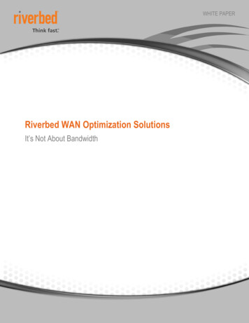
Solution architecture overviewThe following diagram shows DTLS/TLS tunnels established between the vEdge routers and the vSmart controller,over which OMP runs. The TLOCs are indicated by the colored circles, T1-T4. IPSec tunnels are establishedbetween the TLOCs over each transport. Once the IPSec tunnels are established, BFD is enabled across eachof them.Figure 3. TLOC routes and OMPOMPvSmartDTLS/TLS TunnelIPSec TunnelvE1 TLOCsT1T21.1.1.12.2.2.2vE2 TLOCsOMPUpdateTLOC ge1Transport23.3.3.3.44.4.4T3T43.3.3.34.4.4.4TLOC AttributesT3T4vEdge2Virtual Private Networks (VPNs)In the SD-WAN overlay, Virtual Private Networks (VPNs) provide segmentation, much like Virtual Routing andForwarding instances (VRFs) that many are already familiar with. Each VPN is isolated from one another andeach have their own forwarding table. An interface or subinterface is explicitly configured under a single VPN andcannot be part of more than one VPN. Labels are used in OMP route attributes and in the packet encapsulation,which identifies the VPN a packet belongs to.The VPN number is a four-byte integer with a value from 0 to 65530. There are two VPNs present by default inthe vEdge devices and controllers, VPN 0 and VPN 512. VPN 0 is the transport VPN. It contains the interfaces that connect to the WAN transports. Secure DTLS/TLS connections to the vSmart or between vSmart and vBond controllers are initiated from this VPN. Staticor default routes or a dynamic routing protocol needs to be configured inside this VPN in order to getappropriate next-hop information so the control plane can be established and IPSec tunnels can connect toremote sites. VPN 512 is the management VPN. It carries the out-of-band management traffic to and from the CiscoSD-WAN devices. This VPN is not carried across the overlay network.Cisco Validated Designpage 6
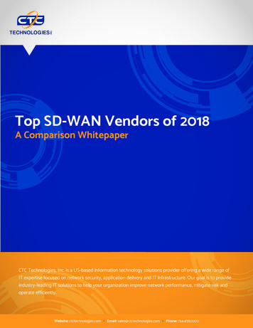
Solution architecture overviewIn addition to the default VPNs that are already defined, one or more service-side VPNs need to be created thatwill contain interfaces that will connect to the local-site network and carry user data traffic. These VPNs can beenabled for features such as OSPF or BGP, Virtual Router Redundancy Protocol (VRRP), QoS, traffic shaping, orpolicing. User traffic can be directed over the IPSec tunnels to other sites by redistributing OMP routes receivedfrom the vSmart controllers at the site into the service-side VPN routing protocol. In turn, routes from the localsite can be advertised to other sites by advertising the service VPN routes into the OMP routing protocol, whichwill be sent to the vSmart controllers and redistributed to the other vEdge routers in the network.The following figure demonstrates VPNs on a vEdge router. The interfaces, ge0/2 and ge0/0, are part of thetransport VPN; ge0/4 and ge0/5 are part of the service VPN, which is attached to the local network at the site;and the mgmt0 port is part of VPN512. Note that while physical interfaces are displayed in the diagram, theinterfaces in the transport and service VPNs could be subinterfaces instead.Figure 4. VPNs on a vEdge INETTransport(VPN0)ge0/5Management (VPN512)mgmt0TLOC extensionA very common network setup in a site with two vEdge routers is for each vEdge router to be connected to justone transport as shown in Figure 4. There are links between the vEdge routers, which allow each vEdge router toaccess the opposite transport through a TLOC-extension interface on the neighboring vEdge router. In the figurebelow, vEdge1 connects directly to the biz-internet transport and uses the TLOC extension interface on vEdge2to connect to the public-internet transport. In turn, vEdge2 connects directly to the public-internet transport anduses the TLOC extension interface on vEdge1 to connect to the biz-internet transport. TLOC extensions can beseparate physical interfaces or subinterfaces.Cisco Validated Designpage 7
Solution architecture overviewFigure 5. TLOC extensionvEdge1biz-internetTLOC ExtensionInterfacevEdge2public-internetWhen you configure the TLOC extension interface, you configure it in VPN 0, assign it an IP address, and thenspecify the WAN interface to which it is bound. In Figure 6, vEdge1’s TLOC extension interface is ge0/7 and isbound to the MPLS transport through ge0/2. vEdge2’s TLOC extension interface is ge0/7 and is bound to theINET transport through ge0/4.Cisco Validated Designpage 8
Solution architecture overviewFigure 6. TLOC e(VPNn)Transport(VPN0)MPLSINET ge0/4ge0/7ge0/2TLOCExtensionSubnet e2 ge0/2DestinationIP net BSubnet ANATTEDvEdge1 ge0/4DestinationIP addressNATTEDvEdge1 ge0/4SourceIP addressINETSome routing considerations need to take place in order for controller reachability to occur and for IPSec tunnelsto come up with other sites over the TLOC extension interfaces. To reach the INET transport, vEdge1’s INETinterface should be configured with a default route pointing to vEdge2’s ge0/7 IP address. If subnet A is in aprivate address space, then NAT should be configured on vEdge2’s ge0/4 transport interface to ensure traffic canbe routed back. To reach the MPLS transport, vEdge2’s MPLS interface should be configured with a default routepointing to vEdge1’s ge0/7 IP address. To ensure traffic can be routed back to the TLOC extension interface, arouting protocol (typically BGP) can be run in the transport VPN of vEdge1 to advertise subnet B so that the MPLSprovider has a route to subnet B through vEdge1.Cisco Validated Designpage 9
Solution architecture overviewBringing the vEdge into the overlayIn order to join the overlay network, a vEdge router needs to establish a secure connection to the vManage sothat it can receive a full configuration, and it needs to establish a secure connection with the vSmart controller sothat it can participate in the overlay network. The discovery of the vManage and vSmart happens automaticallyand is accomplished by first establishing a secure connection to the vBond orchestrator.The following figure shows the sequence of events that occurs when bringing the vEdge router into the overlay.Figure 7. TLOC extensionvBond1Informationon new vEdgeAuthenticationIP addressesof vManageand vEdgeAuthenticationIPSecDTLS/TLSFull configuration fileof vEdge if availablevEdgeOMP sessionestablished andexchangingof routesBFD sessionestablishedvEdge1. Through a minimal bootstrap configuration or through the Zero-Touch Provisioning (ZTP) process, the vEdgerouter will first attempt to authenticate with the vBond orchestrator through an encrypted DTLS connection.Once authenticated, the vBond orchestrator sends the vEdge router the IP addresses of the vManageNetwork Management System (NMS) and the vSmart controllers. The vBond orchestrator also informs thevSmart controllers and vManage of the new vEdge router wanting to join the domain.2. The vEdge router begins establishing secure DTLS or TLS sessions with the vManage and the vSmartcontrollers and tears down the session with the vBond orchestrator. Once the vEdge router authenticateswith the vManage NMS, the vManage with push the full configuration to the vEdge router if available.Cisco Validated Designpage 10
Solution architecture overview3. The vEdge router attempts to establish DTLS/TLS connections to the vSmart controllers over each transportlink. When it authenticates to a vSmart controller, it will establish an OMP session and then learn the routes,including prefixes, TLOCs, and service routes, encryption keys, and policies.4. The vEdge router will attempt to establish an IPSec tunnel to TLOCs over each transport. A TLOC on a privatetransport color attempts to connect to TLOCs on both public and private colors, and a TLOC on a public colortries to connect to other TLOCs on public colors by default. The restrict keyword on the tunnel will only buildtunnels between TLOCs of the same color. BFD will then run over these established connections.See https://sdwan-docs.cisco.com/Product Documentation/Getting Started/Viptela Overlay NetworkBringup/01Bringup Sequence of Events for additional details on the vEdge router and controllerconnection establishment.See https://sdwan-docs.cisco.com/Product Documentation/Software Features/Release 18.1/05Security/01SecurityOverview/Data Plane Security Overview for information on data plane security.Bootstrapping the vEdge routerTwo ways to get a vEdge router up and running on the network is by establishing a console to it and configuringa few configuration lines, or by using ZTP, where you can plug the vEdge router into the network and power it onand it will be provisioned automatically.With the bootstrap configuration method, the idea is to configure the minimum network connectivity and theminimum identifying information along with the vBond orchestrator IP address or hostname. The vEdge router willattempt to connect to the vBond orchestrator and discover the other network controllers from there. In order foryou to bring up the vEdge router successfully, there are a few things that need to be present on the vEdge: Configure an IP address and gateway address on an interface connected to the network, or alternatively,configure Dynamic Host Configuration Protocol (DHCP) in order to obtain an IP address and gateway addressdynamically. The vEdge should be able to reach the vBond through the network. Configure the vBond IP address or hostname. If you configure a hostname, the vEdge router needs to be ableto reach a DNS server in order to resolve it. You do this by configuring a DNS server address under VPN 0. Configure the organization name, system IP address, and site ID. Optionally, configure the host name.Tech tipIn addition to the above requirements, the vEdge router needs to have a valid certificate installed, butcertificates are already installed on hardware-based vEdge routers at the factory. The system clockalso needs to reflect accurate time because of the certificate authentication, and can be set manuallyor through Network Time Protocol (NTP) if need be, but rarely does this need to be addressed whenonboarding new devices.Zero-Touch Provisioning (ZTP) processZTP is an automatic provisioning procedure which starts when the vEdge router is powered up for the firsttime. The vEdge will attempt to connect to a ZTP server with the hostname ztp.viptela.com, where it will get itsvBond orchestrator information. Once the vBond orchestrator information is obtained, it can then subsequentlymake connections to the vManage and vSmart controllers in order to get its full configuration and join theoverlay network.Cisco Validated Designpage 11
Solution architecture overviewFigure 8. Zero-touch provisioning for a vEdge applianceCorporate vBondorchestratorcoryrtoto stractre hedi rcom.cRe te oaelaorptrp.viztpeQu2to13Ico nitiam lcm onun trica oltionZero Touch ProvisioningServer (SaaS service)Assumption*: DHCP on Transport Side (WAN) DNS to resolve ztp.viptela.comvEdge* Factory default configThere are a few requirements for ZTP provisioning: With the hardware vEdge appliances, only certain ports are pre-configured by default to be a DHCP clientinterface and can be used for ZTP. The following table outlines the ports that must be plugged into thenetwork for ZTP to work.Table 1. vEdge ZTP interfacesvEdge modelInterfacevEdge 5000ge0/0 (for network modules in slot 0)vEdge 2000ge2/0vEdge 1000ge0/0vEdge 100bge0/4vEdge 100mge0/4vEdge 100wmge0/4, cellular0Cisco Validated Designpage 12
Solution architecture overview The gateway router for the vEdge router in the network should have reachability to public DNS servers and beable to reach ztp.viptela.com. In vManage, there must be a device configuration template for the vEdge router attached to the vEdgedevice. The system IP address and site ID need to be included in this device template in order for theprocess to work. The ZTP process will not succeed without this.See https://sdwan-docs.cisco.com/Product Documentation/Getting Started/Viptela Overlay NetworkBringup/07Deploy the vEdge Routers/08Prepare vEdge Routers for ZTP for additional information aswell as information on ZTP with wireless routers.Controller connectionsThe secure sessions between the vEdge routers and the controllers (and between controllers), by default areDTLS, which is User Datagram Protocol (UDP)-based. The default base source port is 12346. The vEdge mayuse port hopping where the devices try different source ports when trying to establish connections to eachother in case the connection attempt on the first port fails. The vEdge will increment the port by 20 and try ports12366, 12386, 12406, and 12426 before returning back to 12346. Port hopping is configured by default on avEdge router, but you can disable it globally or on a per-tunnel-interface basis. It is recommended to run porthopping at the branches, but disable this feature in the controllers, and data center, regional hub, or a placewhere aggregate traffic exists. Control connections on vManage with multiple vCPUs will have a different baseport for each vCPU core.For vEdge routers that sit behind the same NAT device and share a public IP address, you do not want eachvEdge to attempt to connect to the same controller using the same public IP and port number. In this case, youcan configure an offset to the base port number of 12346, so the port attempts will be unique among the vEdgerouters. A port offset of 1 will cause the vEdge to use the base port of 12347, and then port-hop with ports12367, 12387, 12407, and 12427. Port offsets need to be explicitly configured, and by default, the port offsetis 0.Alternatively, you can use TLS to connect to the vManage and vSmart controllers, which is TCP-based instead ofUDP-based. vBond controller connections will always use DTLS, however. TCP p
Cisco Validated Design page 3 Solution architecture overview Solution architecture overview The Cisco SD-WAN solution is comprised of separate orchestration, management, control, and data planes. The orchestration plane assists in the automatic