Transcription
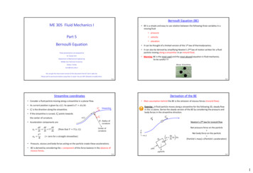
Bernoulli Equation (BE)ME 305 Fluid Mechanics I BE is a simple and easy to use relation between the following three variables in amoving fluid pressurePart 5 velocity elevationBernoulli Equation It can be thought of a limited version of the 1st law of thermodynamics. It can also be derived by simplifying Newton’s 2nd law of motion written for a fluidparticle moving along a streamline in an inviscid fluid.These presentations are prepared byDr. Cüneyt Sert Warning: BE is the most used and the most abused equation in fluid mechanics.So be careful !!!Department of Mechanical EngineeringMiddle East Technical UniversityMovie: StreamlinesAnkara, Turkeycsert@metu.edu.trYou can get the most recent version of this document from Dr. Sert’s web site.Please ask for permission before using them to teach. You are NOT allowed to modify them.5-15-2Streamline coordinatesDerivation of the BE Consider a fluid particle moving along a streamline in a planar flow. Main assumption behind the BE is the omission of viscous forces (inviscid flow). Its current position is given by 𝑠(𝑡). Its speed is 𝑉 𝑑𝑠/𝑑𝑡.𝑒𝑠 𝑒𝑠 is the direction along the streamline.Exercise : A fluid particle moves along a streamline for the following 2D, steady flowin the 𝑥𝑧 plane. Derive the steady version of the BE by considering the pressure andbody forces in the streamline direction.Streamline If the streamline is curved, 𝑒𝑛 points towards𝑠(𝑡)the center of curvature.𝑑𝑉 𝑉 𝑉 𝑉𝑑𝑡 𝑡 𝑠𝑎𝑛 𝑉2ℛ𝑒𝑠𝑔ℛ : Radius ofcurvature Acceleration components are𝑎𝑠 𝑒𝑛(Note that 𝑉 𝑉(𝑠, 𝑡))Newton’s 2nd law for inviscid flowCenter ofcurvature𝑧𝑥( zero for a straight streamline) Pressure, viscous and body forces acting on the particle create these accelerations. BE is derived by considering the 𝑠 component of this force balance in the absence ofviscous forces.𝑝 𝛿𝑠 𝑝𝛿𝑠 𝛿𝑛 𝑠Net pressure force on the particle Net body force on the particle (Particle’s mass) x (Particle’s ���𝑛5-35-41
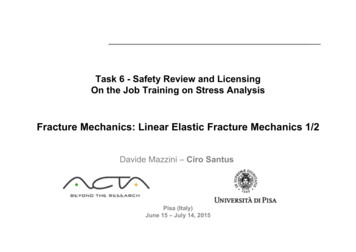
The Most Commonly Used Form of the BEThe Most Commonly Used Form of the BE (cont’d) The following most common form of the BE is valid for steady, incompressible,inviscid flows.𝑝 2 BE can be seen as a balance of kinetic, potential and pressure energies. Consider the flow of water from the syringe. The force applied to the plunger willproduce a pressure greater than atmospheric pressure at point 1. The water flowsfrom the needle (point 2) with relatively high velocity and rises up to point 3 at thetop of its trajectory (Reference: Munson’s book). 𝜌𝑔𝑧 constant along a streamlineUsing two points on a streamline𝑝1 𝜌𝑉 2𝜌𝑉12𝜌𝑉22 𝜌𝑔𝑧1 𝑝2 𝜌𝑔𝑧22221BE can also be understood as “Work done on a fluid particle by pressure and gravityforces is equal to the change in its kinetic energy”. Due to the friction effects (viscous forces) the waterwill not go up as much as predicted by the BE.Exercise : Compare the above BE with the energy conservation equation written fora uniform, steady flow in a single inlet single exit CV. Note that more general forms of the BE also exist for compressible, unsteady flows.5-5BE in ‘‘Head’’ FormExercise : A tube can be used to discharge waterfrom a reservoir as shown. Determine the speed ofthe free jet and the minimum absolute pressure ofwater that occurs at the top of the bend.𝑉2𝑝 𝑧 constant along a streamline𝜌𝑔2𝑔Velocity headTotal head (ℎ𝑇 )Elevationhead5-6Bernoulli Equation Exercises (cont’d) Divide all the terms of the BE by 𝜌𝑔PressureheadSuch effects arise especially at the narrow needle exitand between the water jet and surrounding airstream.BE says that totalhead is constantalong a streamline. In this form all the terms have the units of length and they are called heads. Elevation head : related to the potential energy of the fluid. Pressure head : represents the height of column of the fluid that is needed toproduce the pressure 𝑝. Velocity head : represents the vertical distance needed for the fluid to fall freely(neglecting friction) if it is to reach velocity 𝑉 from rest.1m3mThis is known as siphoning. It can be used to draingas from the tank of an automobile. Once youestablish the initial flow by sucking gas from thetube, the gas will flow by itself.Exercise : Consider the flow of air around a cyclistmoving through still air with velocity 𝑉. Determinethe pressure difference between points 1 and 2.Hint : Be careful about the unsteadiness of the flowfield.5-721𝑉5-82
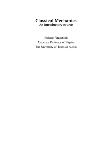
Pressure Variation Normal to the Streamlines Pressure Variation Normal to the Streamlines (cont’d)We can also study the force balance normal to the streamline (in the 𝑛 direction). ℛ corresponds to a straight streamline. ℛ corresponds to a change in the flow direction, i.e. a curved streamline. Thisis accomplished by the appropriate combination of pressure gradient and fluidweight normal to the streamline. If gravitational effects are negligible (gas flows), or if the flow is in a horizontal plane𝑠𝑔𝑛 (pointing towards the center of curvature)𝑧ℛ : Radius of curvature Center of curvature For steady flows we obtain the following equation (see Munson’s book for details) 𝜌𝑔 Therefore when streamlines are curved, pressure increases with distance away fromthe center of curvature. The pressure difference is used to balance the centrifugal acceleration associatedwith the curved streamlines.𝑉2𝑑𝑧 𝑝 𝜌𝑑𝑛 𝑛ℛ 𝑝 𝜌𝑉 2 𝑛ℛ(𝑉 2 ℛ) is the centrifugalPressure increasesin – 𝑛 directionMovieFree vortexacceleration due to directionchangeCurved streamlinesof a flow field𝑛5-95-10Pressure Variation Normal to the Streamlines (cont’d) Static, Dynamic, Stagnation & Total PressuresFor straight and parallel streamlines (ℛ ) pressure variation across thestreamlines is hydrostatic (as if the fluid is not moving)𝑔𝑝 𝜌𝑉 2 𝜌𝑔𝑧 constant along a streamline2Static pressurePressure variation normal to thestreamlines is as if the fluid isstatic (not moving)Dynamic pressureStagnation pressureStraight and parallelstreamlines of a flowfield (ℛ )𝑛 𝑧From Slide 5-9: 𝜌𝑔 𝑑𝑝 0𝑑𝑧HydrostaticpressureBE says that totalpressure is constantalong a streamline.Total pressure(Fluid statics equation)This fact will be used in studying speed measurement with a Pitot tube.5-11 Static pressure is also known as the thermodynamic pressure. To measure it onecould move with the fluid, thus being static relative to the moving fluid. It can alsobe measured using a piezometer tube (as will be seen later). Dynamic pressure represents the rise in pressure as a fluid slows down along astreamline (see the next page). At a stagnation point 𝑉 0, and stagnation and static pressures are equal.5-123
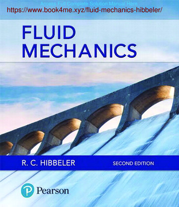
Static, Dynamic, Stagnation & Total Pressures (cont’d)Simple Pitot Tube Pitot tube is a device used for speed measurement.Exercise : Consider the inviscid, incompressible, steady flow along the horizontalstreamline A-B in front of the sphere. Analytical work yields the following fluidvelocity equation along this streamline.𝑉 𝑉0 1 It is a simple tube with a 90 degree bend. It measures flow speed using the Bernoulli principle.𝑅3𝑥3Determine the pressure variation along the streamline from point A far away fromthe sphere (𝑥𝐴 , 𝑉𝐴 𝑉0 ) to point B on the sphere (𝑥𝐵 𝑅 , 𝑉𝐵 𝑉0B𝑅Pitot tube on a Formula 1 car𝑥Pitot tubes on a passanger aircraft Read about the role of Pitot tube malfunctions on plane 362487/plane crashes and pitot tubes.html?cat 155-135-14Simple Pitot Tube (cont’d)𝑝𝑎𝑡𝑚ℎ1ℎ0𝑥𝑜Use of Pitot Tube with a Piezometer Fluid flows in an open channel from left to right. We want to measure the speed at point 𝑥. Fluid fills the Pitot tube and rises inside it to alevel of ℎ1 above the free surface. For the flow in a closed channel or pipe weneed to use an additional tube called thepiezometer tube (static tube).ℎ1ℎℎ00𝑥 The aim of using a Pitot tube is to create astagnation point at point ‘‘𝑜’’ with zero velocity.Exercise: Show that the fluid speed at point 𝑥 is given by𝑉𝑥 𝑝𝑎𝑡𝑚ℎ22𝑔ℎ1 With a Pitot tube we actually measure the pressure difference between points ‘‘𝑥’’and ‘‘𝑜’’ and convert this difference to a speed difference using the BE. Piezometer is used to measure the staticpressure at point 𝑥 as𝑜𝑝𝑥 𝑝𝑎𝑡𝑚 𝜌𝑔(ℎ0 ℎ2 ) Using the Pitot tube : 𝑝𝑜 𝑝𝑎𝑡𝑚 𝜌𝑔(ℎ0 ℎ1 ) BE between points 𝑥 and 𝑜 gives the unknown speed as : 𝑉𝑥 𝑉𝑥 5-152(𝑝𝑜 𝑝𝑥 )/𝜌2𝑔(ℎ1 ℎ2 )5-164
Combined Pitot-Static Tube (Prandtl’s Tube)𝜌𝑥𝑎𝑜ℎ𝑚𝜌𝑚Combined Pitot-Static Tube (cont’d) Instead of measuring static pressure at point 𝑥using a piezometer tube, a second tube is usedaround the Pitot tube. Typical pressure variationalong a combined Pitotstatic tube is as shown. Static pressure holes (point 𝑎) of the outer tubeare located such that they measure correctupstream static pressure, i.e. 𝑝𝑎 𝑝𝑥 . As seen, the holes arelocated such that theymeasure the static pressureahead of the device. Two tubes provide the necessary pressuredifference measurement using the mercury in it. It is possible to use pressure transducers insteadof mercury columns to obtain accurate digitalreadings. The required pressure difference is 𝑝𝑜 𝑝𝑥 𝜌𝑚 𝜌 𝑔ℎ𝑚 Using this in the BE we get𝑉𝑥 2(𝑝𝑜 𝑝𝑥 )/𝜌 𝑉𝑥 2𝑔ℎ𝑚Munson’s textbookExercise: Water flows through the pipecontraction shown. For the given 0.2 mdifference in the manometer level, determinethe flow rate if the small pipe diameter isa) 𝐷 0.05 m,𝜌𝑚 1𝜌b) 𝐷 0.03 m5-17Be Careful in Using the Bernoulli Equation5-18Extended Bernoulli Equation (EBE) The simplest and the most commonly used BE that we studied in the previous slidesmay lead to unphysical results for problems similar to the following ones. It is a modified version of the BE to include effects such as viscous forces, heattransfer and shaft work. BE will be extended in the next slide to solve some of these problems. Remember the energy conservation equation for a single inlet, single exit CV withuniform properties.𝑞 𝑤𝑠 𝑢 𝑝 𝑉2 𝑔𝑧𝜌 2 𝑢 exit𝑝 𝑉2 𝑔𝑧𝜌 2inlet Arranging this equation we get𝑝 𝑉2 𝑔𝑧𝜌 2 inletOriginal BEÇengel and Cimbala’s book5-19𝑝 𝑉2 𝑔𝑧𝜌2 𝑢exit 𝑢inlet 𝑞 𝑤𝑠exitFrictional work perunit mass (𝑤𝑓 )Shaft work doneper unit mass5-205
Extended Bernoulli Equation (cont’d)𝑉2𝑝 𝑔𝑧𝜌 2 1𝑉2𝑝 𝑔𝑧𝜌212 Flow is from location 1 (upstream) to location 2 (downstream). Shaft work (𝑤𝑠 ) 2 𝑤𝑓 𝑤𝑠‘‘Head’’ Form of the EBEStreamline𝑤𝑓Dividing both sides of the EBE by 𝑔 we get𝑝𝜌𝑔𝑤𝑠 For a turbine, which converts hydraulic energy into mechanical energy, the work isdone by the fluid and 𝑤𝑠 is negative. For a pump, which converts mechanical energy into hydraulic energy, the work isdone on the fluid and 𝑤𝑠 is positive.Pressurehead 𝑉22𝑔Velocityhead 𝑧 1Elevationhead𝑝𝑉2 𝑧𝜌𝑔 2𝑔 ℎ𝑓 ℎ𝑠2Total head at 2(ℎ𝑇 2 )FrictionheadPump orturbine headTotal head at 1(ℎ𝑇 1)Frictional work (𝑤𝑓 ) is the amount of mechanical energy converted into thermalenergy due to viscous action. EBE can simply be written hasℎ𝑇 1 ℎ𝑇 2 ℎ𝑓 ℎ𝑠 It corresponds to a rise in the internal energy of the fluid (heat up the fluid) or tothe heat that is lost to the surroundings. Although possible heat addition to the fluid is also included in this term, it isalmost always used to represent a loss (a positive quantity in the above equation).orℎ𝑇 2 ℎ𝑇 1 ℎ𝑓 ℎ𝑠Total head at a downstream location is equal to the total head at an upstreamlocation minus the head loss due to frictional losses plus the head due to shaft work.5-215-22Pump and Turbine Head (ℎ𝑠 ) Extended BE ExercisesPump head ℎ𝑠 is related to the power delivered to thefluid by the pump (𝒫𝑓 ) as follows𝒫𝑓 𝑚𝑤𝑠 𝜌𝑄𝑤𝑠 𝒫𝑓 𝜌𝑔𝑄ℎ𝑠where 𝑄 is the volumetric flow rate that passesthrough the pump. Power delivered to the fluid is related to the powerconsumed by the pump (𝒫pump ) through the pumpefficiency𝒫𝑓𝜂pump 𝒫pumpExercise : The pump shown below pumps water steadily at a volumetric rate of0.005 m3/s through a constant diameter pipe. At the end of the pipe there is anozzle with an exit area that is equal to half of the pipe area. Neglecting frictionallosses, determine the power that must be supplied to the pump, if it is working with70 % efficiency.𝑄2𝑄1Centrifugalpump25 m For a turbine, power extracted from the fluid is calculated in a similar way.Pump9m𝒫𝑓 𝜌𝑔𝑄ℎ𝑠 15 m7mPower produced by the turbine (𝒫turbine ) is smaller than the extracted fluid power𝜂turbine 𝒫turbine𝒫𝑓5-235-246
Extended BE Exercises (cont’d)Toricelli Equation Exercise : A pump is used to transport water between two large reservoirs. Desiredvolumetric flow rate through the suction and discharge pipes is 0.016 m3/s. Crosssectional area of the pipes are 0.004 m2. Total frictional head losses between tworeservoirs is estimated to be 2 m. Efficiency of the pump is 75 %. DetermineConsider the discharge of a liquid from a large reservoir through an orifice (hole). 1𝑝1 𝐻a) the required pump head.2b) the power delivered to the water by the pump.BE between the free surface and the orifice is𝑉2𝜌𝑉12𝜌𝑉22 𝜌𝑔𝑧1 𝑝2 𝜌𝑔𝑧222𝑝1 𝑝2 𝑝𝑎𝑡𝑚 ,𝑧1 𝑧2 𝐻 ,𝑉1 0c) the power required to drive the pump.𝑉2 Dischargereservoir6m(Toricelli Equation) Discharge through the orifice with an area 𝐴𝑜 isMovie : ToricelliSuctionreservoir2𝑔𝐻𝑄orifice 𝑉2 𝐴𝑜PumpDischarge pipe This value will be corrected in the following slides.Suction pipe5-255-26Vena Contracta and Contraction Coefficient Vena Contracta and Contraction Coefficient (cont’d)Depending on the geometry of the orifice, flow field near the exit may be as follows. Vena contracta is the cross section of the jet where thestreamlines are straight and parallel.𝐴𝑗Munson’s book𝐴𝑜 This is the section at which pressure is equal to 𝑝𝑎𝑡𝑚 . Contraction coefficient :𝐴𝑜𝐶𝑐 𝐴𝑗 1𝐴𝑜 𝐴𝑗 𝐴𝑜𝐴𝑗 𝐴𝑜𝐶𝑐 𝐴𝑗 1𝐴𝑜𝐶𝑐 𝐴𝑗 /𝐴𝑜So the correct BE should be written between the free surface and the vena contractasection, shown as 𝑗 below. 01𝜌𝑉𝑗2𝜌𝑉12𝑝1 𝜌𝑔𝑧1 𝑝𝑗 𝜌𝑔𝑧𝑗22𝐻j𝑉𝑗𝑉𝑗 2𝑔𝐻Contractioncoefficient 5-27Discharge through the orifice is 𝑄orifice 𝐴𝑗 2𝑔𝐻 𝑄orifice 𝐶𝑐 𝐴𝑜 2𝑔𝐻5-287
Velocity Coefficient and Discharge CoefficientObstruction Flow Meters The actual discharge would be even less due to viscous effects. Velocity coefficient (𝐶𝑣 ) corrects this to place an obstacle inside the pipeand force the fluid to accelerate andpass from a narrow area.𝑄orifice 𝐶𝑐 𝐶𝑣 𝐴𝑜 2𝑔𝐻Correction due toviscous effectsCorrection due togeometry Discharge coefficient (𝐶𝑑 ) combines contraction and velocity coefficients𝐶𝑑 𝐶𝑐 𝐶𝑣 They are used to measure flow ratesthrough pipes. General idea is Therefore discharge through the orifice can be given asOrificemetermeasure the pressure differencebetween the low-velocity, highpressure upstream and the highvelocity, low-pressure downstream.Nozzle flowmeteruse the BE to relate this pressuredifference to the flow rate in thepipe.VenturimeterMovie : Venturi meter𝑄orifice 𝐶𝑑 𝐴𝑜 2𝑔𝐻 𝐶𝑑 is determined experimentally for a given orifice geometry and for various flowconditions.5-295-30Venturi MeterVenturi Meter (cont’d) 𝐷𝑉1𝑝1 𝑉2𝑑 𝐴1 𝜋𝐷 24𝐴2 𝜋𝑑 24 Section 1 is an upstream section with an average velocity of 𝑉1. We are interested in measuring 𝑉1. Difference between 𝑝1 and 𝑝2 is measured by using static holes. 𝜋𝐷 2𝜋𝑑 2𝑉 𝑉4 14 2Combine these two equations to eliminate 𝑉1 and obtain 𝑉2 as𝑉2 Section 2 is the throat of the Venturi. It is also the vena contracta due to the smoothprofile of the Venturi.𝜌𝑉12𝜌𝑉22 𝑝2 22Continuity equation for a CV between sections 1 and 2𝐴1 𝑉1 𝐴2 𝑉221BE between points 1 and 2 located at the centerline2(𝑝1 𝑝2 )𝜌(1 𝛽4 )where𝑑𝐷 Flow rate through the pipe is given by𝑄 𝐴2 𝑉2 𝐴25-31𝛽 2(𝑝1 𝑝2 )𝜌(1 𝛽4 )5-328
Venturi Meter (cont’d) Orifice Meter This flow rate can be corrected for viscous effects using the discharge coefficient𝑄 𝐶𝑑 𝐴22 (𝑝1 𝑝2 )𝜌 1 𝛽4,𝛽 𝑑𝐷𝐷Experimentally determined andprovided by the manufacturer(see the Slide 5-35). For the orifice meter the expansion is abrupt and 𝐶𝑐 is not 1, i.e. vena contractaarea is smaller than the orifice area.𝑉1o1𝜋𝐷 2𝐴1 4𝑉2𝑑𝜋𝑑 2𝐴𝑜 42𝐴2 𝐶𝑐 𝐴𝑜(vena contracta)For the nozzle flow meter the same equation can be used. Note that for the Venturi meter and the nozzle flow meter, the contraction is smoothand the contraction coefficient is 1 (𝐶𝑐 1).5-33𝐶𝑑 Graphs for Obstruction Flow Meters0.661.000.64𝐶𝑑orificeDVd0.62𝛽 D0.94104105𝛽 0.20.58104105106𝑅𝑒 ise : (Munson’s book) What diameter orifice hole is needed if under idealconditions the flowrate through the orifice meter is to be 113 L/min of water with𝑝1 𝑝2 16.34 kPa ? Pipe diameter is 5 cm and the contraction coefficient is0.63.1.000.98𝐶𝑑VenturiRange of valuesdepending on specificVenturi geometry0.960.94104Following slide 5-32 a new equation can be derived for 𝑉2 . The effect of 𝐶𝑐 1 willbe seen. But in practice the equation of Slide 5-32, derived for Venturi meter, isgenerally used, with 𝐶𝑑 including the effect of 𝐶𝑐 too.Exercise : (Munson’s book) a) Determine the flowrate through the Venturi metershown. b) At what flowrate the cavitation will begin if 𝑝1 376 kPa and vaporpressure of the flowing fluid is 3.6 kPa.0.960.60Section 2 is the vena contracta section. 𝑝2 is measured here. 𝛽 0.8𝐶𝑑nozzle𝑑 0.7𝐷 Obstruction Flow Meter Exercises𝛽 0.20.98 Section o has the orifice plate with the hole diameter 𝑑.105𝑅𝑒1071085-355-369
Obstruction Flow Meters (cont’d) Comparison of obstruction type flow metersOrifice meterNozzle flow meterVenturi meter CostEase of InstallationCheapDifficultPressure LossHighMediumDifficultMediumHighDifficultLowOther types flow meters RotameterThermal flow measurementVortex type flow meter( youtube.com/watch?v 2dfIWNYJwZM )( youtube.com/watch?v YfQSf2NBGqc )( youtube.com/watch?v GmTmDM7jHzA ) Ultrasonic flow meterCoriolis flow measurement( youtube.com/watch?v Bx2RnrfLkQg )( youtube.com/watch?v XIIViaNITIw ) Turbine flow meterWeirs (for open channels)5-3710
Streamline 5-4 Main assumption behind the BE is the omission of viscous forces (inviscid flow). Exercise : A fluid particle moves along a streamline for the following 2D, steady flow in the plane. Derive the steady version of the BE by considering the pressure and body forces in the