Transcription
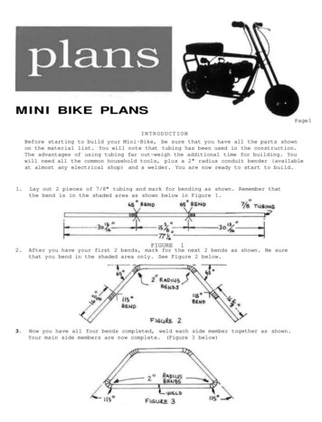
M I N I BIKE PLANSPage 1INTRODUCTIONBefore starting to build your Mini-Bike, be sure that you have all the parts shownon the material list. You will note that tubing has been used in the construction.The advantages of using tubing far out-weigh the additional time for building. Youwill need all the common household tools, plus a 2" radius conduit bender {availableat almost any electrical shop) and a welder. You are now ready to start to build.1.Lay out 2 pieces of 7/8" tubing and mark for bending as shown. Remember thatthe bend is in the shaded area as shown below in Figure 1.2.After you have your first 2 bends, mark for the next 2 bends as shown. Be surethat you bend in the shaded area only. See Figure 2 below.3.Now you have all four bends completed, weld each side member together as shown.Your main side members are now complete. (Figure 3 below)FIGURE1
M I N I BIKE PLANSPage 24.Lay out 2 pieces of 7/8" tubing each 31" long. Mark and bend in shaded area asshown below.5.Cut 2 pieces of 7/8" tubing, with a 5/8" inside diameter, as shown in Figure 5Weld to the 2 pieces of tubing you have just bent as shown in Figure 6.6.Make 2 pieces as shown in Figure 7 out of 1/8" plate steel. There is a fullsize pattern on the back of this sheet. Using 5/8" bolts to line up the platesand the axle, weld the front fork assembly as shown in Figure 8.Note: Be sure that you insert the 5/8" guidebolts as shown in Figure 8. If you don't,the fork assembly will be out of line.
Full size front fork plate pattern to be made out of 1/8" steel plate. 2 required.Full size rear7. Makepagefork1/8"axlesupportto be made outof3/16"plate.2 required.2 rear axle supports out of 3/16" plate as shown in Figure 9. See back of2 for full size pattern. Cut off a piece of 5/8" ID tubing for the frontsupport as shown in Figure 10. Make the motor mount and seat plate out ofplate as shown in Figure 11 and 12. Do not drill holes for the engine yet.
Weld the 2 main side members you have made as shown in Figure 13 below. To holdthe proper distance between each side member, we would suggest that you makewood blocks the proper length to use as spacers between the side members andclamp together before welding. Weld the seat plate as indicated. Next weld thefront foot rest as shown. Weld the front fork tube at the proper angle as indicated. Weld on the 2 rear axle supports so that the bottom of each support isflush with the top of the frame tube. Better use 5/8" axle bolt to make sureyou have lined them up correctly. Be sure to weld to the inside of the frame asshown. Note that you are not to weld the engine mount on yet.9.Bolt on the front fork assembly, using 5/8" x 5" bolt and self-locking nut.Spray paint the entire frame your favorite color.10. Make 2 axles as shown in Figure 14 below using an SAE thread 1 1/2" each end.11. Install the front wheel assembly as shown in Figure 15, using a self-lockingnut at each end of the axle.
12. Weld the brake drum and sprocket assembly to the hub of the rear wheel as shownin Figure 16 below. Before welding check to make sure that you have 3/8" clearance between the sprocket and the tire. Bolt the hub to the rear wheel.13. Install the rear wheel assembly to the frame as shown in Figure 17 below. (Insert the axle through the hub of the wheel, put on 5/8" jam nuts. Then put on awasher on each side and slide onto the frame. Install another washer and 5/8"nut and tighten.)TIRE14. Install your clutch to the engine shaft, keeping the sprocket of the clutch asclose to the engine as possible. Now, place the engine mount on the frame andweld in the proper position. Next, place your engine on the mount, using a chainto line the clutch and rear sprocket. Mark and drill holes and bolt your engineto the mount. Install chain. Connect the twist grip throttle control on theright handle bar to the engine, and brake handle on the left to the brake drum.15. Cut a piece of 3/8" plywood as shown in Figure 18. Cut a piece of 2" or 3" foamthe same size as the plywood. Cover with water resistant fabric, using tacks tofasten the fabric to the plywood. Drill two holes in the seat plate on theframe, and using wood screws, screw the seat to the frame. You are now ready toride your Mini Bike. Drive carefully.
MATERIAL LIST FOR MINI-BIKE1. Steel(a) 20' of 7/8" OD x .085 wall welded 1025 grade tubingfor frame and fork.(b) 7" of 5/8" ID approx. .085 wall seamless 1025tubing for axle and forksupport.(c) 2 pieces of 1/8" plate 3" x 7-1/4" for front forksupport plates.(d) 2 pieces of 3/16" plate 2-1/2" x 3-1/4" for rearaxle support brackets.(e) 1 piece of 1/8" plate 5-1/2" x 5-1/2" for seatplate.(f) 1 piece of 1/8" plate 8-1/8" x 6-1/2" for motormount.(g) 2 pieces of 5/8" steel shaft 7-1/2" long for frontand rear axles.2. EngineShould be of 4 cycle design with approximately 4 to 6horsepower and a 3/4" shaft.3. WheelsYou should have a 4.10 x 3.50 - 4 wheel assembly forthe front and a 4.10 x 3.50 - 5 for the rear withdemountable hub design. Hub should be 1-1/2" indiameter with 5/8" ball bearings.4. BrakeAn internal expansion brake or brake drum and brakeband should be used.
5. ClutchAn automatic clutch with a 12 tooth sprocket for #35chain is needed. The 12 tooth sprocket and the 60 toothrear sprocket give you an ideal gear ratio of 5:1. Besure you order the correct bore for your engine shaft.6. ChainAny good #35 roller chain will work. You will needapproximately 4 feet.7. Throttle ControlA twist grip throttle control with a 7/8" insidediameter for the front handle bar is needed. You willneed about a 34" cable to your engine.8. Brake LeverA brake lever for 7/8" tube and 66" cable are neededfor your brake control.9. Bolts and Nuts(a) 1 only 5/8" x 5" bolt and self-locking nut to hold frontfork to main frame.(b) 4 only 5/8" nuts (not self-locking) for rear axle.(c) 2 only 5/8" self-locking nuts for front axle.(d) 6 only 5/8" washers for front and rear axles.(e) 4 only 1/4" x 1" engine mounting bolts and self-lockingnuts.(f) 2 only wood screws 1/2" roundhead to hold seat to seatplate.10. SeatThe seat fabric should be of a waterproof type. You willneed a piece of 3/8" plywood 7 1/2" wide by 12" long for thebottom board. You will also need a piece of 2 or 3" foam thesame size.11. Handle GripsYou will need 3 only 7/8" handle grips for the handle barsand foot rest.12. PaintPaint should be a spray on type enamel, quick drying. Onesmall can will do.
SOURCESWHEELS. CHAIN, AXLES, THROTTLE CONTROL, HAND BRAKE.AUTOMATIC CLUTCH:Although some of these parts can be purchased from localHardware stores, for convenience we recommend:Karts and Parts7051 Hunters Creek Rd.South Wales, NY 14139phone: 716-655-2883fax: 716-655-2883e-mail: sales@smartkartparts.comNOTE: As a further convenience, the rear wheel assembly,including sprocket and internal expansion brake, can bepurchased fully pre-assembled and ready for installation.ENGINE:Any 3-1/2 to 6 horsepower 4 cycle engine will do. Check withyour local small engine repair shop. If you do not have sucha shop in your area, we recommend:KARTS and PARTSphone: (716) 655-2883
MINI BIKE PLANS Page 2 4. Lay out 2 pieces of 7/8" tubing each 31" long. Mark and bend in shaded area as shown below. 5. 6. Cut 2 pieces of 7/8" tubing, with a 5/8" inside diameter, as shown in Figure 5 Weld to the 2 pieces of tubing you have just bent as shown in Figure 6. Make 2 pieces as s