Transcription
WINE-MATE Cooling UnitUse & Care VINO6500HZDVINO8500HZDVinotemp International Corp.www.vinotemp.comwww.winemate.com
Important Safety Information DO NOT PLUG IN UNTIL 24 HOURS AFTER DELIVERY.DO NOT USE A GROUND FAULT INTERRUPTER (GFI).A DEDICATED 20 OR 30 AMPCIRCUIT IS REQUIRED (1500-4500HZDOR 6500-8500HZD).-1-
TABLE OF CONTENTSFeatures & Specifications. . .3Installation Instruction .5Temperature Control & Humidity Adjustment. .13Care Guide .16Troubleshooting .17Wiring Diagram . 20Customer Support 21Warranty .22-2-
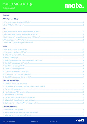
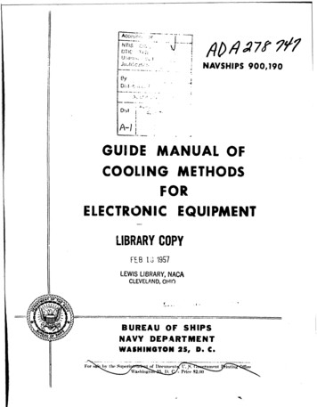
Features and Specifications HZD cooling unit is designed and used to provide a stable temperaturebetween 50 65 F for suitable space at a normal environment.The refrigerated space will maintain humidity of 50 70% RH even whenthe environment becomes dry and humid.These temperatures and humilities are optimized for long term storage ofwine, fur and tobacco.Horizontal cold-air supply is optimized for use in the wide cabinets or winerooms.Self-contained ready for use and easy for installationFig. 1.1 FEATURE DESCRIPTIONS-3-
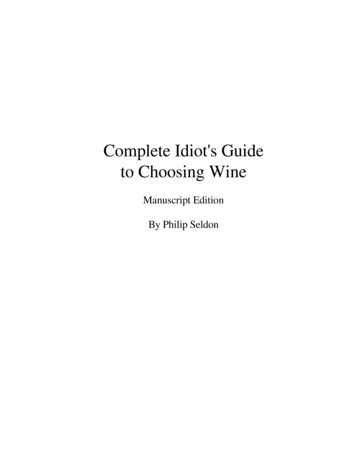
Fig. 1.2 DIMENSIONSThe dimension and capacity are specified as 500500CAPACITY cu ft(55 F/75 5X16X13.2514.25X16X13.2514.25X21.25 X19.7514.25X21.25 X19.7517X28 X2217X28 57575110110NOTES: See the voltage, frequency and current specified on the label at thecooling unit. Capacity is determined under the cabinet and ambient temperatures of55 F and 75 F with R11 interior and R19 exterior insulations. Any lowercabinet and higher ambient temperatures will reduce the capacity.-4-
Installation InstructionSelect a place to mount the unit where the exhaust airflow is unobstructed for aminimum of 6 inch. The area into which the unit exhausts must be well ventilated.If it is not, heat exhausted by the unit will build up and the unit will not operateproperly. The ambient temperatures shall not be higher than 78 F for a VINO1500HZD unit and 95 F for the other units or lower than 50 F. Additionally, coldsupply air from the front grille must remain unobstructed. The unit shall bemounted near the ceiling with equal distance from each side of the cabinet orroom.The cooling unit produces cooling supplied into the cabinet, and it also generatesheat that must be exhausted outside the cabinet. So the cold supply side and hotexhaust side must be separated and sealed. Foam tape may be used to sealthem. The cooling unit must intake adequate fresh ambient-air to work properly.The ambient-air intake and warm-air exhaust must not be short-circulated. Apiece of wood may be used to separate them.NOTES:1) DO NOT INSTALL ANY DUCTS ONTO THE SUPPLY, RETURN, INTAKEAND EXHAUST.2) MOUNTING BRACKETS, SCREWS, GASKETS AND OTHER SEALMATERIALS ARE NOT INCLUDED.1. VINO1500-2500HZD CABINET INSTALLATION Cut a rectangular inside opening with the 1/4” clearance inwards to thewidth and height of the cooling unit. By not going through, leave 1/2” lipinside at the wall to place the gaskets (see Fig 2.1 & 2.2). If top exhaust, cut another rectangular opening at the top of the cabinet tothe length and width of the top exhaust. Make 2 holes at the ceiling to install the 1/4 inside diameter wood threadinserts (see Fig.2.1 & 2.4). Place the gaskets (1/2” foam tape) on the mounting lip sides (see Fig 2.2).-5-
If top exhaust, place another gaskets along the top exhaust at the top ofthe cooling unit (see Fig.2.3).Move the cooling unit towards the mounting sides and push to press thegaskets (see Fig 2.5).Fasten the 2 brackets and use 7/16” wrench to tighten the two ¼” screws(see Fig 2.6).Attach the exhaust and fresh air grille from the rear side of the cellar (seeFig 2.7).Plug the cooling unit in receptacle.Plug the wine cellar.Fig. 2.1 CABINET CUTOUT & GASKET LIP-6-
Fig. 2.2 GASKETFig. 2.3 TOP EXHAUST GASKET-7-
Fig. 2.4 THREAD INSERTFig. 2.5 COOLING UNIT-8-
Fig. 2.6 FASTENING BRACKET & SCREW-9-
Fig. 2.7 CABINET GRILLE2. VINO3500-8500HZD THROUGH WALL INSTALLATION Cut a rectangular opening at the wine room wall as illustrated. Thedimensions of the opening shall be 1/4” larger than the width and height ofthe unit. If top exhaust, cut another rectangular opening at the top of the cabinet tothe length and width of the top exhaust. Construct a shelf as shown. The shelf must be capable of supporting theweight of the unit. Place the unit on the shelf with the back of unit flush with the outside ofthe wall. Attach the grille to the outside wall with screws. Seal the area between the cooling unit and opening with a high qualityweather stripping or polyurethane spray foam and cover with molding. If top exhaust, place another gaskets along the top exhaust at the top ofthe cooling unit (see Fig.2.9).- 10 -
Attach the molding to the wall not the unit.Plug the unit into a properly grounded and dedicated outlet of adequatecapacity.Fig. 2.8 THROUGH WALL INSTALLATIONFig. 2.9 TOP EXHAUST GASKET- 11 -
3. Cellar ConstructionThis is only a guide and shall be considered as minimum requirements.All interior walls and floors shall have a vapor barrier and a minimum of R11insulation. All exterior walls and ceiling shall have a vapor barrier and a minimumof R19 insulation. The vapor barrier shall be installed on the warm side of theinsulation. All joints, door frames, electrical outlets or switches and any pipes orvents that go through the enclosure shall be sealed to prevent air and moistureleakage into the room. Concrete, rock, and brick are not insulation or vaporbarriers.Doors shall be of a minimum size, insulated to at least R11 and tightly sealedwith high quality weather stripping. Be sure to seal the bottom of the door and fillgap between the door’s frame and wall before installing the cap molding.In order to maintain 55 F in the wine cellar, the ambient temperaturesurrounding the enclosure shall not exceed the temperature of the enclosure bymore than 25 F. No enclosure wall shall receive direct sun or strong wind.Lighting shall be of low wattage, with a timer to insure lights are not left on whenthe enclosure is not occupied.The cooling system will not be able to maintain the proper temperature if freshmoisture-laden air is constantly being introduced to the enclosure. Symptoms ofthis condition are; unit runs all the time with only a slight reduction in temperatureand/or water overflows from the unit. Because of the temperature differencebetween the inside and outside, very small cracks can allow large amounts ofoutside air to enter into the enclosure. Please be aware that moisture can passthrough solid concrete, paint and wood. Often a newly constructed room containsfresh wood, paint, concrete and other building materials. These materials containlarge amounts of moisture. When placed into operation in this type ofenvironment, the system will work harder to remove this extra moisture resultingin increased “run” time.4. Electrical CordBecause of potential safety hazards under a certain condition we stronglyrecommend against the use of an extension cord. However, if you still select touse an extension cord, it is absolutely necessary that it is a UL LISTED 3-wiregrounding type appliance extension cord having a 3-blade grounding plug and a3-slot receptacle that will plug into the appliance. The marked rating of theextension cord shall be 115 V, 15 A or equivalent for VINO1500-4500HZD, 115V, 20 A or equivalent for VINO6500-8500HZD and not greater than 15ft in length.- 12 -
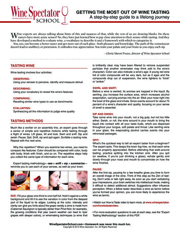
Temperature Control & Humidity Adjustment1. Temperature Setting Set the temperature at 55 F for the optimum aging of wineOn initial start-up, the time required to reach the desired temperaturewill vary, depending on the quantity of bottles, temperature settingand surrounding temperature.Allow 24 hours to stabilize the temperature for each new temperaturesetting operation2. Use of the controllerFig. 3.1 Temperature Controller1) KeysSET: To display target set point; in programming mode it selects a parameter orconfirm an operation.(DEF): To start a manual defrost.(UP): To see the maximum stored temperature; in programming mode itbrowses the parameter codes or increases the displayed value.(DOWN): To see the minimum stored temperature; in programming mode itbrowses the parameter codes or decreases the displayed value.: To turn on/off the power to the unit. : To lock/unlock the keypad.SET : To enter in the programming mode.SET : To return to the temperature display.2) DisplayDuring normal operating conditions, the display shows the value measured bythe air regulation probe. In case of active alarm, the temperature flashesalternately to the code alarm.- 13 -
2.1 LED FUNCTIONCompressor enabledAnti-short cycle enabledDefrost cycle enabledFan enabledFan delay after defrost enabledAlarm occurringTemperature measuring unitProgramming mode3) Alarm Signals3.1 Code DescriptionMESSAGEP1HALACACAUSETemperature probe faultyHigh temperature alarmLow temperature alarmExternal alarmFUNCTIONCompressor switching to Con and CoFOutputs unchangedOutputs unchangedAll outputs off3.2 Alarm RecoveryProbe alarms P1”, start a few seconds after the fault in the related probe; theyautomatically stop a few seconds after the probe restarts normal operation.Check connections before replacing the probe. Temperature alarms “HA”, “LA”automatically stops as soon as the temperature returns to normal value. Alarm“CA” (with i1F PAL) recovers only by switching off and on the instrument.4) Temperature Set-Point4.1 How to see the set-point1. Press and immediately release the SET key, the display will show the set-pointvalue.2. Press again and immediately release the SET key or wait for 5 seconds todisplay the probe value again.4.2 How to change the set-point1. Press the SET key for more than 3 seconds until the “ C” or “ F” LED startsblinking and the set-point will be displayed.2. To change the set value, press the up/down keys / within 10 sec.3. To store the new set-point value, press the SET key again or wait 10 sec.- 14 -
5) Parameter Programming1. Press the SET keys for 3 sec until the “ C” or “ F” LED starts blinking,then release the keys.2. Press again the SET keys for more than 7sec until the Pr2 label will bedisplayed, then release the keys. The first parameter Hy will be displayed.3. Press up/down keys / to select the required parameter within 10 sec.4. Press the “SET” key to display its value.5. Use up/down keysto change its value within 10 sec.6. Press “SET” to store the new value.7. To exit: Press SET or wait 15sec without pressing a LUALLAFHALdFnCFonFoFDESCRIPTIONset-point ( )temperature regulation differential ( )anti-short cycle delay (min)compress on with probe faulty (min)compress off with probe faulty (min)temperature unit ( F/ C)display resolutiontemperature display delay (min)probe calibration ( )maximum set-point ( )minimum set-point ( )defrost cycle interval time (hour)defrost cycle endurance time (min)temperature alarm typehigh temperature alarm ( )low temperature alarm ( )alarm recovery differential ( )temperature alarm delay (min)fan operating modefan on with compressor (min)fan off with compressor (min)VALUE554101530F: Fahrenheitin: integer1065502430rE: relative to set-point10105120C-n: on with compressor & off during defrost015Note: The parameter Fon is used to adjust the humidity in the wine cabinet. Thehigher Fon is, the higher relative humidity will be. The parameter FnC C-y (on with compressor and on during defrost) withidF 8 and MdF 20 can be used to defrost more efficiently in case there ismuch frost. The unit turns on at set-point plus regulation differential Hy after anti-shortcycle AC has elapsed and turns off at set-point.7) Manual DefrostPress the DEF key for more than 2 seconds and a manual defrost will start.- 15 -
Care Guide1. Coil Cleaning Clean the condenser coil regularly. Coil may need to be cleaned at leastevery 6 months.Coil is on the ambient air intake side of the cooling unit.Unplug the unit or disconnect power.Use a condenser brush or a vacuum cleaner with an extended attachment toclean the coil when it is dusty or dirty.Plug the cooling unit or reconnect power.2. Moisture Removing Remove the extra condensate if it is accumulated in the wine cellar at highhumidity condition.3. Drain LineVINO1500-2500HZD units don’t require a drain line. But VINO3500-8500HZDunits are equipped with an additional drain fitting. In case of extreme humiditythere is a drain line needed, remove the drain plug on the bottom left at the rear,then remove the fitting plug and add a 0.375” OD drain tube into the drain fitting.- 16 -
TroubleshootingThis Troubleshooting Chart is not prepared to replace the training required for aprofessional refrigeration service person, not is it comprehensiveComplaint1. Unit notrunning2. Cabinettemperaturehigh, unitstoppingand startingwith shortrunning time3. Temperaturehigh,compressorstoppingand startingbut veryshortrunning time4. Temperaturehigh or notcooling andrunningcontinually;“HA” alarmblinking andbeepingPossible CausesResponsea. Power cord unpluggedb. No power to unitc. Setting higher than ambienttemperatured. Differential too highe. Incorrect or loose wiringsf. Low voltageg. Defrost light blinkingh. Compressor light blinkinga. rature okb. Short circuit of air flow betweensupply and return airc. Setting too highd. Failed temperature controllerand thermistora. Check for power cord plugb. Check power at receptacle & fusesc. Lower temperature settinga. Incorrect voltageb. Failed thermistorc.Failed componentsd.e.f.g.Improper condenser airflowDirty condenserOvercharge of refrigerantDischarge or suction pressuretoo higha. Improper room insulation & sealb. Room too largec. Ambient temperature too highd. Exhaust restrictede. Malfunctioning fansf.Improperevaporatororcondenser airflowg. Dirty Condenserh. Iced evaporatori. Refrigeration system restrictionj.Refrigerant leakk.Undercharge or overcharge- 17 -d.e.f.g.h.a.Decrease the value as to 4 FCheck all wirings and connectionsContact an authorized electricianUnit is under defrost modeUnit waits for anti-short cycle delayMove the air sensor away from theevaporatorb. Deflect the supply air downc. Lower settingd. Call service for diagnosisa. Check for voltageb. Check thermistor by placing it in icewater and measuring resistancec. Check compressor windings, startrelay and overload protector.d. Check for condenser fane. Clean condenserf. Call service for removing refrigerantg. Call service for OEM informationa. Check for insulation, gasket anddoor openingb. Check for excessive sizec. Check for installation locationd. Leave minimum 3 feet clearance forthe exhaust side and leaveminimum 1 foot clearance for thefresh air intake sidee. Check for both evaporator andcondenser fansf. Check for air restrictions, air shortcirculation, grille directionsg. Clean condenserh. Defrost and reset temperaturei. Callserviceforcheckingrestrictionsj. Call service for checking loss ofrefrigerantk. Call service to add or removerefrigerant
l.5. Unit runningtoo longFailed componentsl.a. Improper room insulation & sealb. Exhaust restrictedc. Room too larged. Ambient temperature higher 90 Fe. Dirty Condenser6. Fan motorrunning butcompressornot runninga. Post-compressor fan runningmodeb. Incorrect power supplyc. Incorrect or loose wiringsd. Failed componentse. LiquidrefrigerantcompressorintheCheck compressor windings, startrelay and overload protectora. Check for insulation, gasket anddoor openingb. Leave minimum 3 feet clearance forthe exhaust side and leave minimum1 foot clearance for the fresh airintake sidec. Check for excessive size or increasesettingd. Check for installation location orincrease settinge. Clean condensera. Check for fan running time FONb. Check for proper voltagec. Check all wirings and connectionsd. Check start relay, start capacitor,overload protector, compressor.e. Call service for OEM information.7. Compressorrunning butfan notrunning8. Temperaturefluctuatinga. Fan blade stuckb. Incorrect or loose wiringsc. Failed motorsa. Check for proper clearanceb. Check all wiringsc. Call service for checking open orshorted windingsa. Air sensora. When using an air sensor, the winebottletemperatureismainlycontrolled by the average airtemperature. If the set-point is 55 Fwith the differential 4F, the coolingunit turns on at 59 F of airtemperature and turns off at 55 F ofair temperature. The average airtemperature is 57 F, and then thewine temperature is around 57 /0.5 F. The air is light enough tochange so quickly that it maintainsrelativelyconstantaveragetemperature that would prevent winebottle temperature from fluctuating.9. Fan runningtoo longa. Post-compressor fan runningmode for humidity modulationa. Reset FONa. Anti-short cycle10. Unit notstarting ,buttemperaturerising higha. Reset AC- 18 -
11. Evaporatorfreezing upa. Evaporator air flow restrictionb. Not stopping due to air leak, highambient temperature or lowsettingc. Bad thermostat or sensord. Low ambient temperaturee. Moisture in the systemf. Refrigerant low or leakingg. Capillary tube blockagea. Check for fans & CFMb. Check for seal, door opening,ambient temperature and settingc. Check for thermostat and sensord. Increase defrost cycle and changefan modee. Works initially then stops; Callservice.f. Call service to check for current andsealed system leakageg. Call service to check for capillaryfrost12. Water leaka. Air leak in wine cellarb. Evaporator air flow restriction orlow refrigerantc. Water passages restrictedd. Drip tray leake. High humiditya. Check for any air leakb. Check air flow or air TD crossingevaporatorc. Clean the drip trayd. No water overflow but leake. Use drain line13. Circuittrippinga. Incorrect fuse or breakerb. Incorrect wiringsc. Failed componentsa. Check for proper fuse or breakerb. Check for wirings and connectionsc. Call service14. Noisyoperationa. Mounting area not firmb. Loose partsa. Add support to improve installationb. Check fan blades, bearings, cabinetwashers, tubing contact and loosescrews.c. Check for airflow blockagec.Compressor overloaded due tohigh ambient temperatures orairflow restrictiond. Malfunctioning components- 19 -d. Call service for checking internalloose, inadequate lubrication andincorrect wirings
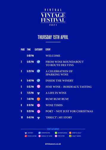
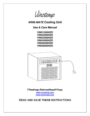
Wiring DiagramFig. 6.1 VINO1500-2500HZD Wiring DiagramFig. 6.3 VINO3500-8500HZD Wiring Diagram- 20 -
Customer SupportIf you still have problems, please contact us at:Vinotemp International17631 South Susana RoadRancho Dominguez, CA 90221Tel: (310) 886-3332Fax: (310) 886-3310Email: info@vinotemp.com- 21 -
WarrantyThank you for choosing a Vinotemp cooling unit.Please enter the complete model and serial numbers in the space provided:ModelSerial No.Attach your purchase receipt to this owner’s manual.1. Limited WarrantyVINOTEMP warrants its products to be free from defects due to workmanship ormaterials under normal use and service, for twelve months after the initial sale. Ifthe product is defective due to workmanship or materials, is removed withintwelve months of the initial sale and is returned to VINOTEMP, in the originalshipping carton, shipping prepaid, VINOTEMP will at its option, repair or replacethe product free of charge. Additionally VINOTEMP warrants all parts to be freefrom defects for a period of sixty months after initial sale.This warranty constitutes the entire warranty of the VINOTEMP with respect to itsproducts and is in lieu of all other warranties, express or implied, including any offitness for a particular purpose. In no event shall VINOTEMP be responsible forany consequential damages what is so ever. Any modification or unauthorizedrepair of VINOTEMP products shall void this warranty.Service under WarrantyThis service is provided to customers within the continental UNITED STATESonly. VINOTEMP cooling units are warranted to produce the stated number ofBTU/H. While every effort has been made to provide accurate guidelines,VINOTEMP can not warranty its units to cool a particular enclosure.In case of failure, VINOTEMP cooling units must be repaired by the factory or itsauthorized agent. Repairs or modifications made by anyone else will void thewarranty.Shall a VINOTEMP cooling unit fail, contact the dealer for instructions, do notreturn the unit to the factory without authorization from VINOTEMP. If the unitrequires repair, re-pack it in the original shipping carton and return it to thefactory, shipping prepaid. VINOTEMP will not accept COD shipments. If the unit- 22 -
is determined to be faulty and is within the twelve month warranty periodVINOTEMP will, at its discretion, repair or replace the unit and return it free ofcharge to the original retail customer. If the unit is found to be in good workingorder, or beyond the initial twelve month period, it will be returned freight collect.2. Limitation of Implied WarrantyVINOTEMP’S SOLE LIABILITY FOR ANY DEFECTIVE PRODUCT IS LIMITEDTO, AT OUR OPTION, REPAIRING OR REPLACING OF UNIT.VINOTEMP SHALL NOT BE LIABLE FOR:DAMAGE TO OTHER PROPERTY CAUSED BY ANY DEFECTS IN THE UNIT,DAMAGES BASED UPON INCONVENIENCE, LOSS OF USE OF THE UNIT,LOSS OF TIME OR COMMERCIAL LOSS, ANY OUTER DAMAGES,WHETHER INCIDENTAL, CONSEQUENTIAL OR OTHERWISE.THIS WARRANTY IS EXCLUSIBE AND IS IN LIEU OF ALL OTHERWARRANTIES, EXPRESSED OR INPLIED, INCLUDING BUT NOT LIMITEDTO, IMPLIED WARRANTIES OF MERCHANTABILITY OR FITNESS FOR APARTICULAR PURPOSE.While great effort has been made to provide accurate guidelines VINOTEMPcannot warrant its units to properly cool a particular enclosure. Customers arecautioned that enclosure construction, unit location and many other factors canaffect the operation and performance of the unit. There for suitability of the unitfor a specific enclosure or application must be determined by the customer andcannot be warranted by VINOTEMP.- 23 -
displayed, then release the keys. The first parameter Hy will be displayed. 3. Press up/down keys / to select the required parameter within 10 sec. 4. Press the “SET” key to display its value. 5. Use up/down keys to change its value within 10 sec. 6. Press “SET” to store the new