Transcription
G. C. E. (Advanced Level)PHYSICSPractical Handbook(effective from year 2017)Department of ScienceFaculty of Science and TechnologyNational Institute of Educationwww.nie.lk
G. C. E. (Advanced Level)PhysicsPractical Handbook National Institute of EducationISBN: -Department of ScienceNational Institute of EducationWebsite : www.nie.lkii
Message from the Director GeneralWith the intention of realising the National Educational Objectives recommended by theNational Education Commission and with the primary intention of developing commoncompetencies, the content based curriculum which was earlier effective was modernisedand the first phase of the new competency based curriculum of an eight year cycle wasintroduced by the National Institute of Education to the primary and the secondaryeducation system of Sri Lanka in 2007.Based on the facts revealed by research and the suggestions by various sectors oneducation, a curriculum rationalization process has resulted in the second phase of thecurriculum cycle which has commenced its introduction from 2015.The primary intention of the new rationalized curriculum is to admit the student communityinto a more student centered and activity based education pattern while transforming to ahuman resource armed with skills and competencies required for the world of work.In this rationalization process, to orderly build up all subject competencies from baselevel to the higher level the vertical integration method has been employed, while tominimise as much as possible the repetition of the same subject matter over and overagain and to limit the subject content and develop a student friendly curriculum which canbe implemented, the horizontal integration method has been employed.In teaching - learning process of science, practical work is an important component. Theengagement in practical work at a high level enables the students to develop their talents,to understand the scientific investigation process and enhance their conceptual knowledge.This practical handbook is prepared with the intention of guiding both the teacher - studentsectors to successfully perform activities of planning practical experiments, efficientengagement of students in the learning process and uplifting their practical talents in thefield of Physics.I take this opportunity to convey my gratitude to the members of the Council and ofthe Academic Affairs Board of the NIE and the resource persons who contributed tothe preparation of this practical handbook for their dedication to achieve success in thismatter.Dr. (Mrs) T. A. R. J. GunasekaraDirector GeneralNational Institute of EducationMaharagamaiii
Message from the Director (Science)This practical handbook has been compiled to assist the student in reaching expertisein the subject area of science. We have been in commutation with university lecturers,teachers and curriculum experts during the designing of this book. The experimentsin this handbook are introduced with the intention of achieving the objectives of thephysics curriculum. Stated below are three reasons which may be interrelated regardingthe importance of performing practical experiments in school, but can be mentioned asseparate ones.1.Assistance to build up scientific concepts (knowledge and comprehension) andintegration of theoretical matters with practical matters2.Developing investigational talents3.Building up practical talents and to excel in itDuring performing and experimenting we believe that the teacher being concerned ofthe above mentioned reasons would assist the student to have a better understanding ofthe subject, to uplift in him/ her the talents possessed by a scientist, to have manipulativeskills required for further education and job oppertunities connected with STEM subjects(Science, Technology, Engineering and Mathematics). In order to make practical workeffective, the laboratory should be made a place of learning by doing. Also, the teachershould provide guidance to maintain the following norms inside the laboratory. Keeping the place of work clean High concern by students about their activities Keeping the tables of the laboratory free of stoppers of chemical bottles Minimising wastage of water, gas and electricity Reading carefully and following the guidance provided for the respective experiment Teachers should allow the student’s entry in lab in his/ her presence Performing only those experiments allocated by the teacherI take this opportunity to express my gratitude to all university lecturers, teachers andother resource persons who contributed in their endeavour to the successful production ofthe practical handbook. Also finally I wish that this attempt will be helpful to strengthenour young generation as members of societies rich in information and technologicallyadvanced.Dr. A. D. Asoka de SilvaDirectorDepartment of ScienceNational Institute of Educationiv
Resource Contribution (2018 revised copy)GuidanceDr. (Mrs) T. A. R J. Gunasekara, Director General,National Institute of EducationSupervisionDr. A. D. Asoka de Silva, Director,Department of Science, National Institute of EducationSubject leadershipP. Malavipathirana, Senior Lecturer,Department of Science, National Institute of EducationEditingP. Malavipathirana, Senior Lecturer,National Institute of EducationDr. M. L. S. Piyatissa, Assistant Lecturer,Department of Science, National Institute of EducationMiss R. A. Amarasinghe, Assistant Lecturer,Department of Science, National Institute of EducationEnglish translationD. S. Withanachchi, Former Chief Project Officer(Education Technology), National Institute of EducationEnglish languageeditingDr. (Mrs.) Chandra AmarasekaraConsultant, National Institute of EducationTypesetting andpage designingJayaruwan Vijayawardhana,Freelance Computer Graphic DesignerLaboratory assistanceM. Welipitiya, Laboratory Assistant,Department of Science, National Institute of EducationOther assistance(Mrs) W. P. P. Weerawardhana, Department of Science,National Institute of EducationK. R. Dayawansa, Department of Science,National Institute of Educationv
Resource Contribution (2015 First Copy)InstructionsProf. W. M. Abeyrathna BandaraDirector General, National Institute of EducationGuidance and directionM. F. S. P. Jayawardena, Deputy Director General,Faculty of Science and Technology,National Institute of EducationSubject coordinationM. L. S. Piyatissa, Assistant Lecturer,Department of Science, National Institute of EducationEditingP. Malavipathirana, Senior Lecturer,Department of Science, National Institute of EducationM. L. S. Piyatissa, Assistant Lecturer,Department of Science, National Institute of EducationMrs. M. R. P. I. J. Herath, Assistant Lecturer,Department of Science, National Institute of EducationW. D. I. Upamal, Assistant Lecturer,Department of Science, National Institute of EducationMiss R. A. Amarasinghe, Assistant Lecturer,Department of Science, National Institute of EducationPanel of writersP. Malavipathirana, Senior Lecturer,Department of Science, National Institute of EducationW. A. D. Rathnasuriya,Former Chief Project Officer (Physics),National Institute of EducationB. A. Tilakaratne, Former Project Officer (Physics),National Institute of EducationD. S. Vithanachchi,Former Chief Project Officer (Education Technology),National Institute of EducationH. S. K. Wijethilake, Former SLEAS - IA. Sugathapala, Former Teacher Service - IA. Hettiarachchi, Senior Program Officer,National Education CommisionSubject guidenceand evalutionEmeritus Professor of Physics, T. R. AriyaratneProf. S. R. D. Rosa, University of ColomboProf. J. K. D. S. Jayanetti, University of Colombovi
Dr. M. K. Jayananda, University of ColomboProf. K. P. S. C. Jayarathne, University of ColomboProf. D. D. N. B. Daya, University of ColomboDr. I. K. Perera, Former Senior ProfessorDr. G. M. L. P. Aponsu,Sabaragamuwa University of Sri LankaDr. B. S. B. Karunaratne, Former Senior ProfessorDr. P. W. S. K. Bandaranayake, University of PeradeniyaDr. L. R. A. K. Bandara, University of PeradeniyaDr. (Mrs.) V. A. Seneviratne, University of PeradeniyaDr. J. P. Liyanage, University of PeradeniyaDr. C. P. Jayalath, University of PeradeniyaProf. J. C. N. Rajendra, Open University of Sri LankaProf. W. G. D. Dharmarathne, University of RuhunaDr. J. A. P. Bodhika, University of RuhunaProf. S. R. D. Kalingamudali, University of KelaniyaDr. P. Geekiyanage, University of Sri JayewardenepuraIndependentevaluationP. Wickramasekara, Teacher Service - I,Buddhist Girls' College, Mount LaviniaJ. R. Lankapura, Teacher Service - I,Wickramashila Central College, GiriullaDiagramsW. A. D. RathnasuriyaFormer Chief Project Officer (Physics)National Institute of EducationJ. R. Lankapura, Teacher Service - I,Wickramashila Central Collage, GiriullaJayaruwan Vijayawardhana,Freelance Computer Graphic DesignerLaboratory assistanceM. Welipitiya, Lab Assistant,Department of Science, National Institute of EducationOther assistanceMrs. W. P. P. Weerawardena,Department of Science, National Institute of EducationK. R. Dayawansha,Department of Science, National Institute of Educationvii
IntroductionThe Physics practical handbook has been prepared by the Science Department of theNational Institute of Education for the use of both teachers and students by includingdetailed instructions on 42 laboratory experiments related to the Physics (AdvancedLevel) syllabus effective from the year 2017. The list of practical experiments on the2017 syllabus is included in the pages x and xi of the handbook. Although the practicalhandbook serves both teachers and students, it is advisable that student will alwaysengage in practicals with the teacher knowledge and guidence. Both teacher-studentsectors should take care to adlere to the ethics and the safety measures as relevant insidethe laboratory.In this book, for each experiment, after the name of the experiment are lists. Necessaryinformation is provided with materials and apparatus, theory, method, readings andcalculations, conclusions and relevant illustrations. Special details to be mentioned aregiven under the caption ‘note’. The record of the experiment should be prepared by thestudent under proper guidance. In addition to the experiments given here in, in order tostrengthen the learning-teaching process, the teacher has the freedom to plan more relevantpractical activities, teacher demonstrations and practical experiments etc. Instructionsare given to restrict the usage of mercury as much as possible. The first copy of this bookwas prepared and completed in the year 2015 as a book of instructions for 46 laboratoryexperiments pertaining to the syllabus that was efective from the year 2009 (and revisedin the year 2012). Almost all the experiments here had been tested when preparing thatbook. When the book was edited to suit the new syllabus which came into effect from2017, the following main amendments were effected. Removal of following experiments from the 2009 practical list.Experiment No. Name of experiment32Comparison of two resistances using the metre bridge35Comparison of resistances using the potentiometer37Determination of very small e.m.f.s (that of a thermocouple)using the potentiometer44Determination of the surface tension of a soap film using awire frameIn experiment no. 24: ‘To verify the relationship between the pressure of a gas and itsabsolute temperature at constant volume’, explanation of the usage of the ‘Bordenpressure gauge’ instead of the ‘constant volume gas apparatus’ was instituted.viii
In addition, a special matter that should be brought to the notice of the teachers is thatthey have many opportunities for research activities on Physics education in field such asplanning practical experiments, improving and evaluating them.Furthermore, if the Department of Science is made aware of any defects and ommissionsetc of the experiments in this book it will be of great help in future revisions.ix
Practical list for the G. C. E. (Advanced Level)Physics Syllabus effective from the year 20171.Usage of the vernier callipers2.Usage of the micrometer screwgauge3.Usage of the spherometer4.Usage of the travelling microscope5.Verification of the law of parallelogram of forces and using it to determine themass of a body6.Determination of the mass of a body using the principle of moments7.Determination of the relative density of a liquid using the U tube8.Determination of the relative density of a liquid using Hare’s apparatus9.Determination of the density of a liquid using a weighted test tube10.Determination of the acceleration due to gravity using the simple pendulum11.Verification of the relationship between the mass of a body suspended from a helixspring and its period of oscillation12.Determination of the frequency of a tuning fork using the sonometer13.Verification of the relationship between the frequency of a stretched string and itsvibrating length using the sonometer14.Determination of the velocity of sound using a closed resonance tube and a tuningfork and also determination of the end correction of the tube15.Determination of the velocity of sound in air using a closed resonance tube and aset of tuning forks and also determination of the end correction of the tube16.Determination of the refractive index of glass using the travelling microscope anda block of glass17.Determination of the angle of minimum deviation of a prism by observing thevariation of deviation in a ray caused by the prism18.Determination of the refractive index of the material of a prism by the criticalangle method19.Adjustment of a spectometer and using it for determination of the refracting angleof a prism20.Determination of the angle of minimum deviation of a prism and the refractiveindex of the material of the prism using the spectrometer21.1. Location of the images formed by a convex lens by the method of no-parallax andhence determination of the focal length of the lens21.2. Location of the images formed by concave lens by the method of no-parallax andhence determination of the focal length of the lensx
22.Determination of the atmospheric pressure using the quill tube23.Verification of the relationship between the volume and the temperature of a gas atconstant pressure24.To verify the relationship between the pressure and the absolute temperature of agas at constant level25.Determination of the specific heat capacity of a solid substance by the method ofmixtures26.Determination of the specific heat capacity of a liquid by the method of cooling27.Determination of specific latent heat of fusion of ice by the method of mixtures28.Determination of the specific latent heat of vaporization of water by the method ofmixtures29.Determination of relative humidity of air using a polished calorimeter30.Determination of the thermal conductivity of a metal by Searle’s method31.Determination of the internal resistance and the electromotive force of a dry cell32.Determination of temperature coefficient of resistance of a metal (Cu) using theMetre Bridge33.Comparison of electromotive forces of two cells using the potentiometer34.Determination of the internal resistance of a cell using the potentiometer35.Construction of the I-V curve for a forward biased semiconductor diode36.Construction of the transfer characteristic curve between IB and IC of a transistor incommon emitter configuration37.Experimental investigation of the truth tables of simple fundamental logic gatesand hence identification of the given gates38.Determination of the Young’s modulus of a metal (steel) in the form of a wire39.Determination of the coefficient of viscosity of a liquid (water) by capillary flowmethod using Poiseuill’s formula40.Determination of the surface tension of water using a microscope slide41.Determination of the surface tension of water by capillary rise method42.Determination of the surface tension of a liquid by Jaeger’s methodxi
6.17.18.19.20.Message from the Director GeneralMessage from the Director (Science)IntroductionPractical ListUsage of the vernier callipersUsage of the micrometer screwgaugeUsage of the spherometerUsage of the travelling microscopeVerification of the law of parallelogram of forces and using it todetermine the mass of a bodyDetermination of the mass of a body using the principle of momentsDetermination of the relative density of a liquid using the U tubeDetermination of the relative density of a liquid using Hare’s apparatusDetermination of the density of a liquid using a weighted test tubeDetermination of the acceleration due to gravity using the simplependulumVerification of the relationship between the mass of a body suspendedfrom a helix spring and its period of oscillationDetermination of the frequency of a tuning fork using the sonometerVerification of the relationship between the frequency of a stretchedstring and its vibrating length using the sonometerDetermination of the velocity of sound using a closed resonance tubeand a tuning fork and also determination of the end correction of thetubeDetermination of the velocity of sound in air using a closed resonancetube and a set of tuning forks and determination of the end correction ofthe tubeDetermination of the refractive index of glass using the travellingmicroscope and a block of glassDetermination of the angle of minimum deviation of a prism byobserving the variation of deviation of a ray caused by the prismDetermination of the refractive index of the material of a prism by thecritical angle methodAdjustment of a spectometer and using it for determination of therefracting angle of a prismDetermination of the angle of minimum deviation of a prism and therefractive index of the material of the prism using the 343638404245
5.36.37.38.39.40.41.42.Location of the images formed by a convex lens by the method of noparallax and hence determination of the focal length of the lensLocation of the images formed by concave lens by the method of noparallax and hence determination of the focal length of the lensDetermination of the atmospheric pressure using the quill tubeVerification of the relationship between the volume and the temperatureof a gas at constant pressureTo verify the relationship between the pressure and the absolutetemperature of a gas at constant levelDetermination of the specific heat capacity of a solid substance by themethod of mixturesDetermination of the specific heat capacity of a liquid by the method ofcoolingDetermination of specific latent heat of fusion of ice by the method ofmixturesDetermination of the specific latent heat of vaporization of water by themethod of mixturesDetermination of relative humidity of air using a polished calorimeterDetermination of the thermal conductivity of a metal by Searle’s methodDetermination of the internal resistance and the electromotive force ofa dry cellDetermination of temperature coefficient of resistance of a metal (Cu)using the Metre BridgeComparison of electromotive forces of two cells using thepotentiometerDetermination of the internal resistance of a cell using thepotentiometerConstruction of the I-V curve for a forward biased semiconductor diodeConstruction of the transfer characteristic curve between IB and IC of atransistor in common emitter configurationExperimental investigation of the truth tables of simple fundamentallogic gates and hence identification of the given gatesDetermination of Young’s modulus of a metal (steel) in the form of awireDetermination of the coefficient of viscosity of a liquid (water) bycapillary flow method using Poiseuill’s formulaDetermination of the surface tension of water using a microscope slideDetermination of the surface tension of water by the capillary risemethodDetermination of the surface tension of a liquid by Jaeger’s 9699Referencesxiii
xiv
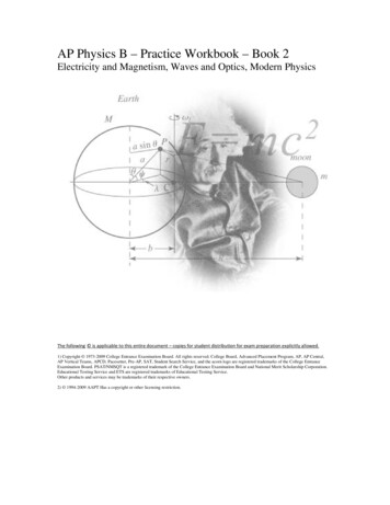
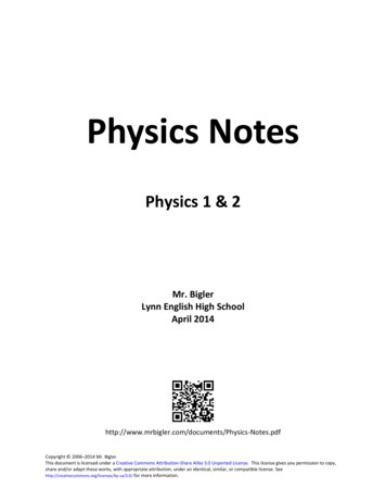
Experiment No.01Usage of the vernier callipers1. Finding the volume of a block of wood2. Finding the volume of the material of a PVC tubing3. Finding the volume of the material of a solid sphere4. Finding the internal volume of a hollow cylinderMaterials and apparatusA vernier calliper, a block of wood (of about 2 cm 4 cm 6 cm), a PVC tubing (1.3 cm (1 2"),6 cm), a solid sphere (of diameter about 2 cm) and a hollow cylinder (Archemedes cylinder andbucket)TheorySliding jawInternal jawsPinFixed jawVernier scaleExternal jawsMain scaleFigure 1.1 Vernier callipersVernier scaleLeast count 1 –9 10( )110Main scaleFigure 1.2 Magnified view of the vernier scale and the main scaleIf the vernier calliper of the school laboratory has n divisions of its main scale divided intoN divisions of the vernier scale,n length of a smallest division of the main scaleLeast count in relevant units 1 –N()1. If the length is l, breadth is b and height is h of the wooden block, its volume l b h2. If the external diameter is d0, the internal diameter is d1 and length is l of the tube,d0 2di 2– pVolume of the material of the tube pl22[ ( ) ( )]( )3. If the diameter of the sphere is d, its volume 4p3d234. If the depth of the hollow cylinder is l and its internal diameter d,d 2the volume of the cavity of the tube pl2( )1
MethodFind and note down the least count of the given vernier calliper.1. Measurment of length, breadth and height of the wooden block When taking measurments of the block hold it betweenthe jaws of the caliper and calculate readings.Figure 1.3 Take measurments at three places for length, breadthand height and note down readings in Table 1.1.2. Finding the volume of the material of the PVC tubingFigure 1.4Figure 1.5 When measuring the external diameter of the PVC tubing adjust the vernier caliper as shownin Figure 1.4 and calculate readings. Take measurments of two diameters normal to each other and record in Table 1.2 When measuring the internal diameter of the tubing adjust the vernier caliper as shown inFigure 1.5 and obtain readings. Take measurments of two diameters normal to each other and record in Table 1.2 Measure the length of the tubing in three positions and record in Table 1.2(Take care to select these three positions keeping equal gaps between them.)3. Finding the volume of the material of a solid sphere Figure 1.6When measuring the diameter of the sphere adjust thevernier caliper as shown in Figure 1.6 and calculatethe readings. Take measurments of two diameters normal to eachother and note down in Table 1.42
4. Finding the internal volume of a hollow cylinder Calculate the internal diameter of the hollow cylinder as shownearlier in Figure 1.5 and note down in Table 1.5 When measuring the depth of the cavity, adjust the vernier calliperas shown in Figure 1.7 and take readings in three places. Note downreadings in Table 1.6.Figure 1.7Readings and calculationsLeast unit of vernier caliper–.Zero error of vernier caliper–.1. Measurments of wooden blockTable 1.1Corrected reading(i)(ii)(iii)Mean Value (cm)(iii)Mean Value (cm)(iii)Mean value (cm)length l (cm)breadth b (cm)height h (cm)2. Measurments of PVC tubingTable 1.2Corrected reading(i)(ii)Internal diameter d1 (cm)External diameter d2 (cm)Table 1.3Corrected reading(i)(ii)length (cm)3
3. Measurments of solid sphereTable 1.4Corrected reading(i)(iii)Mean value (cm)(iii)Mean value (cm)(iii)Mean value (cm)Diameter of sphere d (cm)4. Mesurments of hollow cylinderTable 1.5Corrected reading(i)(ii)Internal diameter d (cm)Table 1.6Corrected reading(i)(ii)Depth l (cm)Calculate according to relevant theory.ResultRecord your results in accordance with the above calculations.DiscussionPresent your opinion about the concluded results and their errors and also your sugestions onobtaining more accurate results.NoteIt is important to read the zero error of a vernier calliper according to the position of its zeromark and also to decide whether the correction should be subracted from or added to the relevantmeasurment.Figure 1.9Figure 1.10The above diagram illustrates how the zero error is indicated in two different vernier callipers whentheir vernier scales are adjusted to bring their jaws to touch each other.4
According to Figure 1.9 the zero error (the gap between the zero of the vernier scale andthat of the main scale) can be read directly from the scale. This value is 0.3 mm. The correctreading should be the distance moved by the vernier scale. The movement of the vernierscale starts from this position. But readings are recorded from the zero of the main scale.Hence for correction, this value (0.3 mm) should be subtracted from the relavant reading.According to Figure 1.10, for zero error, the gap between the zero of the vernier scale and thezero of the main scale cannot be obtained directly from the readings shown on the scale. Thegap of the vernier divisions up to the reading at coincidence should be found and from it thegap of the main scale divisions should be subtracted to find the zero error.zero error (8 0.9 - 7.0) mm (7.2 - 7.0) mm 0.2 mmFor correction this value (0.2 mm) should be added to the relevant reading.A more convenient method exists to determine the zero error. The value corresponding to thereading at coincidence should be first subracted from the sum of all divisions in the vernierscale and this value has to be multiplied by the least count of the vernier scale.Accordingly,zero error (10 - 8) 0.1 mm 0.2 mm5
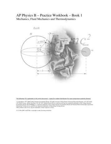
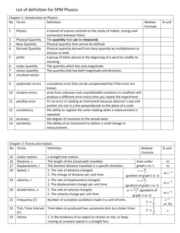
Experiment No.02Usage of the micrometer screwgauge1. Finding the diameter of a thin wire2. Finding the diameter of a steel/ glass ball3. Finding the thickness of a microscope slide4. Finding the thickness of a photocopy paperMaterials and apparatusA micrometer screwgauge (of about gauge 22), a thin wire, a steel ball (a ball bearing of about 5mm), a microscope slide and a photocopy paper.TheoryIf x is the pitch of the screw and n the number of divisions on the circular scale, then,xLeast count of the instrument in relevant units nAnvilSpindleThimbleThimble headFigure 2.1 Micrometer screwgaugeMethodObtain the least count of the micrometer screwgauge. Rotate holding thimble head only until thespindle touches the anvil (when the spindle touches the anvil or when these two are in contact withany other object the thimble head would rotate freely making a “ticking” sound) Note down anyzero error if shown.1.To measure the diameter of the wire place it between the anvil and the spindle and rotatethe thimble head until the wire is held properly between those two. Obtain the value of thediameter. Rotate the wire by 90 and obtain reading again. Repeat these measurments forthree places of the wire and enter the corrected readings in Table 2.1.6
2.Arrange the ball to fit properly between the anvil and the spindle and obtain readings for threediameters normal to each other. Enter the corrected readings in Table 2.2.3.Arrange the microscope slide to fit between the anvil and the spindle and obtain readings forthickness of the slide in three different places. Enter the corrected readings in Table 2.3.4.Cut the photocopy paper into 20 pieces, place the pieces one over the other into a bundleand obtain readings for thickness of the bundle at three different places. Enter the correctedreadings in Table 2.4.Readings and calculationsLeast count of the micrometer screwgauge–.Zero error–.Table 2.1Diameter of wire (mm)(i)(ii)(iii)Mean diameter(mm)(iii)Mean diameter(mm)Table 2.2Diameter of ball (mm)(i)(ii)Table 2.3Thickness of microscope slide (mm)(i)(ii)(iii)Mean thickness(mm)Table 2.4Thickness of 20 pieces (mm)Correctedreading(i)(ii)(iii)7Mean thickness Mean thicknessof 20 piecesof paper(mm)(mm)
ResultsRecord your results according to the above calculations.DiscussionPresent your opinions about the concluded results and their errors and also your sugestions forobtaining more accurate results.NoteIt is important to read the zero error according to the position of the zero of the circular scale relatedto the line of the main scale of a micrometer screwgauge and also to decide whether for correctionthis value should be subracted from or added to the relevant measurment.Figure 2.2Figure 2.3Above figures illustrate two ways of indicating the zero error in two micrometer screwgauges whenthe thimble heads are rotated to bring the anvil and the spindle to touch each other.According to Figure 2.2 the zero error (the gap between the main scale line and the zero of thecircular scale) is 0.02 mm Accordingly the zero of the circular scale is situated below the main scaleline. The rotation of the circular scale begins from 0.01 mm. Hence for correction this value shouldbe subtracted from the relevant reading.According to Figure 2.3 the zero of the circular scale is situated above the main scale line.Accordingly the zero error is 0.01 mm. The zero of the circular scale will coincide with the mainscale line only when it is rotated by 0.01 mm towards the main scale line. Hence for correction thisvalue should be added to the relevant reading. When measuring the thickness of a photocopy paperthe number of paper pieces should be selected to obtain a thickness reading so that the percentageerror with respect to the least count of the instrument is less than or equal to 1%.8
Experiment No.03Usage of the spherometer1. Finding the thickness of a microscope slide2. Finding the radius of curvature of a spherical surfaceMaterials and apparatusa spherometer, plane (optically flat) piece of glass, a microscope slide and a clock glass and a metreruler or a vernier calliperTheoryIf the screw pitch of the spherometer is x and the number of divisions of the circular scale isy, thenxLeast count yIf h is the height from the plane of the leg tips up to the point at which tthe screw tip touchesthe curved surface, a the gap between the two legs of the
v Resource Contribution (2018 revised copy) Guidance Dr. (Mrs) T. A. R J. Gunasekara, Director General, National Institute of Education Supervision Dr. A. D. Asoka de Silva, Director, Department of Science, National Institute of Education Subject leadership P. Malavipathirana, Senior Lecture