Transcription
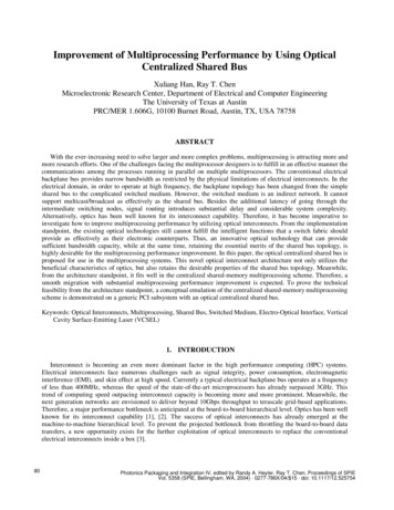
Improvement of Multiprocessing Performance by Using OpticalCentralized Shared BusXuliang Han, Ray T. ChenMicroelectronic Research Center, Department of Electrical and Computer EngineeringThe University of Texas at AustinPRC/MER 1.606G, 10100 Burnet Road, Austin, TX, USA 78758ABSTRACTWith the ever-increasing need to solve larger and more complex problems, multiprocessing is attracting more andmore research efforts. One of the challenges facing the multiprocessor designers is to fulfill in an effective manner thecommunications among the processes running in parallel on multiple multiprocessors. The conventional electricalbackplane bus provides narrow bandwidth as restricted by the physical limitations of electrical interconnects. In theelectrical domain, in order to operate at high frequency, the backplane topology has been changed from the simpleshared bus to the complicated switched medium. However, the switched medium is an indirect network. It cannotsupport multicast/broadcast as effectively as the shared bus. Besides the additional latency of going through theintermediate switching nodes, signal routing introduces substantial delay and considerable system complexity.Alternatively, optics has been well known for its interconnect capability. Therefore, it has become imperative toinvestigate how to improve multiprocessing performance by utilizing optical interconnects. From the implementationstandpoint, the existing optical technologies still cannot fulfill the intelligent functions that a switch fabric shouldprovide as effectively as their electronic counterparts. Thus, an innovative optical technology that can providesufficient bandwidth capacity, while at the same time, retaining the essential merits of the shared bus topology, ishighly desirable for the multiprocessing performance improvement. In this paper, the optical centralized shared bus isproposed for use in the multiprocessing systems. This novel optical interconnect architecture not only utilizes thebeneficial characteristics of optics, but also retains the desirable properties of the shared bus topology. Meanwhile,from the architecture standpoint, it fits well in the centralized shared-memory multiprocessing scheme. Therefore, asmooth migration with substantial multiprocessing performance improvement is expected. To prove the technicalfeasibility from the architecture standpoint, a conceptual emulation of the centralized shared-memory multiprocessingscheme is demonstrated on a generic PCI subsystem with an optical centralized shared bus.Keywords: Optical Interconnects, Multiprocessing, Shared Bus, Switched Medium, Electro-Optical Interface, VerticalCavity Surface-Emitting Laser (VCSEL)1. INTRODUCTIONInterconnect is becoming an even more dominant factor in the high performance computing (HPC) systems.Electrical interconnects face numerous challenges such as signal integrity, power consumption, electromagneticinterference (EMI), and skin effect at high speed. Currently a typical electrical backplane bus operates at a frequencyof less than 400MHz, whereas the speed of the state-of-the-art microprocessors has already surpassed 3GHz. Thistrend of computing speed outpacing interconnect capacity is becoming more and more prominent. Meanwhile, thenext generation networks are envisioned to deliver beyond 10Gbps throughput to terascale grid-based applications.Therefore, a major performance bottleneck is anticipated at the board-to-board hierarchical level. Optics has been wellknown for its interconnect capability [1], [2]. The success of optical interconnects has already emerged at themachine-to-machine hierarchical level. To prevent the projected bottleneck from throttling the board-to-board datatransfers, a new opportunity exists for the further exploitation of optical interconnects to replace the conventionalelectrical interconnects inside a box [3].80Photonics Packaging and Integration IV, edited by Randy A. Heyler, Ray T. Chen, Proceedings of SPIEVol. 5358 (SPIE, Bellingham, WA, 2004) · 0277-786X/04/ 15 · doi: 10.1117/12.525754
As multiprocessing comes into the mainstream, the board-to-board interconnects become even more critical. Onesignificant challenge in the design of a multiprocessing system is to fulfill in an effective manner the communicationsamong several processes that are simultaneously running on multiple processors. The shared bus topology is thepreferred interconnect scheme because its broadcast nature can be effectively utilized to reduce communicationlatency, lessen networking complexity, and support cache coherence in a multiprocessing system [4]. However, thephysical length, the number of fan-outs, and the operation speed of the backplane bus impose strict limitations onelectrical interconnects. Thus, the switched backplane with switch fabrics and simple point-to-point interconnectionsis currently being employed in the electrical domain. By changing the backplane topology from the shared bus to theswitched medium, however, several crucial performance aspects are compromised. The switched medium cannotcarry out broadcast as effectively as the shared bus. Besides the additional latency of going through the intermediateswitching nodes, signal routing introduces substantial delay and considerable complexity, which has become athrottling factor in the high-end multiprocessing systems [5]. Therefore, an innovative optical technology that canprovide sufficient bandwidth capacity, while at the same time, retaining the essential merits of the shared bus topologyis highly desirable for multiprocessing performance improvement.At the board-to-board level, optical implementation techniques can be classified into three basic categories: opticalwaveguide interconnects, free-space optical interconnects, and substrate-guided optical interconnect, as illustrated inFig. 1. Similar to metal traces, optical waveguides can be laid out on a board, but essentially for point-to-pointinterconnects. Although free-space approaches provide some routing flexibility, the backplane topology is stillconstrained to point-to-point. Meanwhile, the free-space optical data links are open to the environmental noise. Thisproblem can be avoided by confining optical signals within a waveguiding substrate. As illustrated, the optical signalthat carries the data at the source is coupled into the substrate by a properly designed holographic grating. At thesubstrate/air interface, the incident angle is prescribed to be larger than the critical angle. Thus, this light cannotescape from the confinement of the substrate under the total internal reflection (TIR) condition [6]. At the destination,another properly designed holographic grating couples the light back into the free space to the photodiode. In thismanner, an optical link from the source to the destination is established. With the appropriate design of the types ofthe holographic gratings and their relative positions, signal broadcast can be effectively implemented. Thus, it ispossible to utilize this method to develop optical backplane buses.As one of the most significant contributions to the efforts on optical backplane bus, an innovative architecturecalled optical centralized shared bus was developed [7]. To the best of our knowledge, this is the first architecture thatis able to achieve equalized bus fan-outs in the optical domain. Since the critical optical/electrical interface becomesuniform across the entire backplane bus, this merit can considerably save the system power budget to maintain therequired bit error rate (BER) and substantially ease the overall system integration. Based on this architecture, wepropose in this paper to apply the optical centralized shared bus in the multiprocessing systems for performanceimprovement. After a brief overview of the centralized shared-memory multiprocessing scheme in Section 2, thearchitectural features of the optical centralized shared bus will be presented in the context of the centralized sharedmemory multiprocessing in Section 3. A preliminary feasibility demonstration on a generic PCI subsystem will bedescribed in Section 4. Finally, a summary is given in Section 5.2. CENTRALIZED SHARED-MEMORY MULTIPROCESSINGIn the centralized shared-memory multiprocessing model, as illustrated in Fig. 2, multiple processors share a singlephysical memory on a shared bus [4]. The term of shared-memory refers to the fact that the address space is shared,i.e., the same physical address on different microprocessors refers to the same location in the main memory. Thisshared address space can be used to communicate data implicitly via the load and store operations. The advantages ofthe shared-memory communications mainly include [4]: Ease of programming when the communication patterns among the microprocessors are complex or varydynamically during execution. Also, this advantage simplifies the compiler design. Lower communication overhead and better use of the available bandwidth. This arises from the implicit nature ofcommunication and the use of memory mapping to implement protection in hardware rather than through theoperating system.Proc. of SPIE Vol. 535881
Capability of automatic caching of all data, both shared and private. Caching provides both decreased latency andreduced contention for accessing the shared data, and thus the frequency of the remote communications can beminimized.Caching is a widely applied technique to improve system performance by utilizing the locality of the programs.The centralized shared-memory multiprocessing model supports automatic caching of all data, both shared andprivate. The private data are accessible only for a single processor, while the shared data for multiple processors. Thecommunications among the processors are essentially carried out via the read and write operations upon the shareddata. When a private item is cached, its location is migrated to the cache, reducing the average access time as well asthe memory bandwidth required. Since no other processors use the private data, the program behavior is identical tothat in a uniprocessing system. When a shared item is cached, the shared value may be replicated in multiple caches.In addition to the reduction in the access latency and required memory bandwidth, this replication also lessens thecontentions that may exist for the shared items that are being accessed by multiple processors at the same time. Theshared bus topology plays a pivotal role for the correct functioning of the centralized shared-memory multiprocessingscheme. To ensure the consistency of the shared memory seen by each processor, all caches must be retained incoherence. Since only one processor can deliver data on the shared bus at a time, the write operations upon the sharedmemory are forced in a sequential order. In the centralized shared-memory multiprocessing scheme, this property iscalled write serialization [4]. Meanwhile, all cache controllers snoop on the shared bus that carries all actual dataexchanges. Because of the broadcast nature of the shared bus topology, all processors can simultaneously monitorevery access to the shared memory, and quickly determine whether or not they have a cached copy of the item beingtransferred. Accordingly, the cached copies may be either invalidated or updated with the detected new value. In thismanner, cache coherence is consistently maintained across the whole system.As expected, the performance of a centralized shared-memory multiprocessing system is critically dependent onthe shared bus that carries out all inter-processor communications and broadcast actions for maintaining cachecoherence. In the electrical domain, the anticipated performance bottleneck essentially originates from the restrictedbandwidth capacity of the shared bus. The physical length, the number of fan-outs, and the operation speed of thebackplane bus are significantly restricted by the physical limitations of electrical interconnects. Thus, the switchedbackplane with switch fabrics and simple point-to-point interconnections is currently being employed in the high-endmultiprocessing systems. By changing the backplane topology from the shared bus to the switched medium, however,several crucial performance aspects, e.g., interconnect latency, are compromised. The switched medium is an indirectnetwork, and thus cannot carry out broadcast as effectively as the shared bus. Besides the additional latency of goingthrough the intermediate switching nodes, signal routing introduces substantial delay and considerable systemcomplexity. In Ref. [5], the statistics of the memory read latency in a medium and a large size switch-basedmultiprocessing system shows that the wire delay is only a moderate fraction of the total memory read latency, incontrast, the transactions through switches and the multicast/broadcast actions to maintain cache coherence are asignificant fraction, furthermore, the delay associated with switching and cache coherence increases with the systemscale more rapidly than the wire delay. Meanwhile, the additional involvement of many expensive devices, such asswitch fabrics and transceiver modules, tremendously increases the overall system cost. In consequence, there wouldbe few prominent benefits if simply replacing electrical wires with optical point-to-point interconnections. Withoutall-optical switching, the additional optical domain overhead, i.e., the optical-to-electrical and electrical-to-opticalconversions at the interface of the switch fabric, could even make worse the latency problem in the switch-basedmultiprocessing systems. Therefore, an innovative optical technology that can provide sufficient bandwidth capacity,while at the same time, retaining the essential merits of the shared bus topology is highly desirable for theperformance improvement in a centralized shared-memory multiprocessing system.3. OPTICAL CENTRALIZED SHARED BUS ARCHITECTUREFig. 3 illustrates the architectural concept of the optical centralized shared bus [7]. For simplicity, only five slots(#A1, #A2, #B1, #B2, and #C) are drawn in this schematic. In the context of the centralized shared-memorymultiprocessing, a memory board is to be inserted into the central slot (#C), while the other slots (#A1, #A2, #B1, and#B2) on the backplane bus are for processor boards. The electrical backplane provides interconnects for the noncritical paths. The electro-optical transceivers, including VCSELs (vertical-cavity surface-emitting lasers) and82Proc. of SPIE Vol. 5358
photodiodes, are integrated at the bottom of the electrical backplane, and aligned with the underlying opticalinterconnect layer. Therefore, the insertion/removal of the boards during the normal operations does not affect thecritical alignment. Different from other modules, the positions of the central VCSEL and photodiode are swapped asindicated in Fig. 3. The configured optical interconnect layer consists of a waveguiding plate with the properlydesigned volume holographic gratings integrated on its top surface. The plate provides a turbulence-free medium foroptical interconnects, and the waveguide holograms function as optical fan-in/fan-out devices. Underlying the centralslot (#C) is an equal-efficiency double-grating hologram, while the others are single-grating holograms. By employingsuch a unique configuration, both broadcastability and bi-directionality of signal flows on the backplane bus areenabled [7], which are the essential obstacles to achieving equalized bus fan-outs in the other optical shared busarchitectures [8], [9].The optical centralized shared bus well fits in the centralized shared-memory multiprocessing scheme from thearchitecture standpoint. The memory integrated on the central board functions as the centralized shared memory. For awrite operation upon the shared memory, as illustrated in Fig. 3, the VCSEL of the source processor board emits thelight that carries the data and projects it surface-normally onto its underlying waveguide hologram. This light iscoupled into the optical waveguiding plate by the grating and propagates within the confinement of the plate under thetotal internal reflection (TIR) condition [6]. Then, it is surface-normally coupled out of the plate by the central doublegrating hologram and detected by the central photodiode. Because there is only one photodiode inside the centralelectro-optical transceiver module, the data deliveries from the processor boards on the backplane to the memoryboard are forced in a sequential order as in the centralized shared-memory multiprocessing scheme, i.e., writeserialization. Subsequently, cache coherence is ensured in a simple broadcast fashion. The central VCSEL generatesthe outbound optical signal that carries the updated data and projects it surface-normally onto its underlying doublegrating hologram. This light is coupled into the plate and equally diffracted into two beams by the hologram,propagating along the two opposite directions within the confinement of the plate under the total internal reflection(TIR) condition [6]. During the propagation, a portion of the light is surface-normally coupled out of the plate by thesingle-grating hologram underlying each processor board on the backplane and detected by the photodiode. Bysnooping on the shared bus, all processor boards can immediately obtain the updated data from the centralized sharedmemory, and then either invalidate or update the cached copies. In this manner, cache coherence is consistentlymaintained across the whole system.The volume holographic gratings integrated on the top surface of the waveguiding plate function as optical fanin/fan-out devices. Their diffraction properties in the Bragg regime can be analyzed with Kogelnik’s Coupled WaveTheory [10]. By balancing the diffraction efficiency of the waveguide holograms in use, the bus fan-outs across theentire optical interconnect layer can be equalized as demonstrated in Fig. 4 [11]. This merit is highly desirable fromthe system integration standpoint because of the reduced constraint on the dynamic ranges of the electro-opticaltransceiver modules in use. Compared with electrical interconnects, the most significant benefit of opticalinterconnects is the tremendous gain in the bandwidth capacity. In Ref. [12], the bandwidth capacity per substrateguided optical line was experimentally characterized to be approximately 2.5THz. With such an enormous busbandwidth, the interconnect bottleneck in the centralized shared-memory multiprocessing scheme would becompletely eliminated by employing the optical centralized shared bus.4. DEMONSTRATION ON PCI SUBSYSTEMThe real implementation of the centralized shared-memory multiprocessing scheme by employing the opticalcentralized shared bus certainly involves too many processor-specific issues. Meanwhile, the advancedmicroprocessors are upgrading at a rapid pace, probably with different micro-architectures from one generation to thenext. With the focus on demonstrating the technical feasibility in a general scenario, a conceptual emulation of thecentralized shared-memory scheme was carried out on a generic PCI subsystem that incorporated an opticalcentralized shared bus.PCI stands for Peripheral Components Interconnect. It defines a local bus architecture that is not specific to anyparticular processor [13]. A processor is connected to the root PCI bus through a compatible chipset, which isfrequently referred to as the North Bridge. The use of the North Bridge isolates the generic PCI local bus from thespecific processor bus. There are two participants in every PCI data transaction: master, or called initiator, and target.Proc. of SPIE Vol. 535883
The master is the device that initiates the data transfer, and the target is the device that is addressed by the master forthe purpose of performing the data transfer. It is very important to note that the PCI data transfers can beaccomplished in the burst mode [14]. A burst transfer consists of a single address phase followed by two or more dataphases, and the master has to arbitrate for the bus ownership only one time for the whole block of the data to betransferred. Thus, the arbitration overhead is largely reduced, and the available bus bandwidth may be fully utilizedfor the actual data transfers. During the address phase, the start address and transaction type are issued in a broadcastfashion on the shared bus. The targeted device latches the start address into an address counter, claims the transaction,and is responsible for incrementing the address from one data phase to the next. As the master is ready to transfer eachdata item, it informs the target whether or not it is the last one, and the entire PCI burst transaction completes whenthe final data item has been transferred.The centralized shared-memory multiprocessing scheme was conceptually emulated on a generic PCI subsystem asshown in Fig. 5. The electrical part of this system is consisted of a passive PCI backplane, a single board computer(SBC) card, a Gigabit Ethernet Network Interface Card (NIC), and a PCI memory card. As illustrated by theconnectivity diagram in Fig. 5 (b), the PCI memory card function as the centralized shared memory as in thecentralized shared-memory multiprocessing scheme. The SBC card contains a 1.2GHz microprocessor and a NorthBridge that controls the interface to the PCI backplane. The microprocessor can access to the PCI memory cardthrough the North Bridge. The NIC card is connected to another workstation through a RJ-45 crossover cable. Withthe capability to request for the bus ownership, the NIC card can initiate PCI data transactions targeting the PCImemory card without any CPU actions on the SBC card. Thus, the communications between the NIC card and theSBC card can proceed via the PCI memory card on the shared bus in a conceptually equivalent manner to the sharedmemory communications among multiple processors in a centralized shared-memory multiprocessing system.As shown in Fig. 6, the optical centralized shared bus was integrated underneath the PCI backplane, where theequalized bus fan-outs were established across the entire optical interconnect layer. As a preliminary attempt, onlyPCI bus line AD02 was replaced by the optical interconnection link while the other electrical wires on the passive PCIbackplane were remained. In order to incorporate the optical interconnect layer into the generic PCI subsystem, aspecial extension interface was developed, as shown in Fig. 7, to be integrated with the AD02 pins of the PCI slots onthe backplane. It contains an electro-optical transceiver module and the required logic controls in consistent with thePCI protocol. A single electrical PCI bus line carries bi-directional signal transmissions. Meanwhile, the commercialPCI core does not explicitly indicate the actual data transfer direction. The data transaction type, either read or write,is negotiated between the master and the target in an implicit manner involving several PCI bus signals [14]. Thus, alogic-interpreting circuit was implemented, as illustrated in Fig. 7 (b), to generate the RACTIVE and TACTIVEcontrol signal, as illustrated in Fig. 7 (a), to appropriately coordinate the operations of the electro-optical transceivermodules during the PCI data transfers.From the operating system standpoint, the PCI memory card was actually treated as a RAM disk after mounting afile system. To conceptually emulate the shared-memory communications among multiple processors in a centralizedshared-memory multiprocessing system, the same file was transferred from the NIC card to the PCI memory card, andthen from the PCI memory card to the SBC card. On the shared bus, the signal waveforms during the PCI datatransfers were captured in the real time by the bus analyzer card as shown in Fig. 5 (a). This bus analyzer card wasconnected to a logic analyzer (HP1660ES) for the logic timing verification. In particular, the signal waveformspresented at the AD02 pins of the NIC card and the PCI memory card were displayed on an oscilloscope for the directvisualization of the implemented optical interconnection during the PCI data transfers. Fig. 8 is one of the capturedresults during such tests, where Channel 1 displays the signal waveforms at the AD02 pin of the NIC card, which werethe modulation inputs to the VCSEL driver inside its extension interface module, and Channel 2 displays the signalwaveforms at the AD02 pin of the PCI memory card, which were the outputs from the edge detector inside itsextension interface module. The obtained results of these tests verified the correct connectivity of the implementedoptical interconnection link.5. CONCLUSIONThe optical centralized shared bus utilizes the enormous bandwidth capacity of substrate-guided opticalinterconnects, while at the same time, retaining the desirable architectural features of the shared bus. Its unique84Proc. of SPIE Vol. 5358
topological configuration enables the fulfillment of equalized optical bus fan-outs across the entire architecture, andthus a uniform electrical/optical interface can be obtained. This significant achievement is highly desirable from thesystem integration standpoint. Meanwhile, it is particularly pointed out in this paper that this innovative architecturewell fits in the centralized shared-memory multiprocessing scheme. As a preliminary attempt, a conceptual emulationof the centralized shared-memory multiprocessing scheme was carried out on a generic PCI subsystem thatincorporated an optical centralized shared bus. Since this research prototype originated from the existing system, theactual data transfers were still at the same standard PCI bus speed (33MHz) as without using optical interconnects.Apparently, the compromise is that it cannot exhibit any performance improvement since the terahertz bandwidthpotential of optics is not utilized in the constructed prototype. Nonetheless, the objective of the demonstrationpresented herein is to prove the technical feasibility from the architecture standpoint. Because there is no doubt on theinterconnect capability of optics, which has been confirmed both theoretically and experimentally, it can be projectedfor sure that the interconnect bottleneck of the shared bus in the centralized shared-memory multiprocessing systemwould be completely eliminated by employing the optical centralized shared bus.ACKNOWLEDGEMENTThe authors would like to thank BMDO, DARPA, ONR, AFOSR, and the ATP program of the State of Texas forsupporting this work.REFERENCES1.2.3.4.5.6.7.8.9.10.11.12.13.14.M. R. Feldman, S. C. Esener, C. C. Guest, and S. H. Lee, “Comparison between optical and electricalinterconnects based on power and speed characteristics,” Applied Optics, vol. 27, pp. 1742-1751, May 1988.E. D. Kyriakis-Bitzaros, N. Haralabidis, M. Lagadas, A. Georgakilas, Y. Moisiadis, and G. Halkias, “Realisticend-to-end simulation of the optoelectronic links and comparison with the electrical interconnections for systemon-chip applications,” IEEE Journal of Lightwave Technology, vol. 19, pp. 1532-1542, October 2001.A. F. J. Levi, “Optical interconnects in systems,” Proceedings of the IEEE, vol. 88, pp. 750-757, June 2000.D. A. Patterson, J. L. Hennessy, “Computer architecture: a quantitative approach,” 2nd Edition, Chapter 8,Morgan Kaufmann Publishers, August 1995.D. Huang, T. Sze, A. Landin, R. Lytel, and H. Davidson, “Optical interconnects: out of the box forever?” IEEEJournal on Selected Topics in Quantum Electronics, vol. 9, pp. 614-623, March/April 2003.K. Brenner, F. Sauer, “Diffractive-reflective optical interconnects,” Applied Optics, vol. 27, pp. 4251-4254,October 1988.X. Han, G. Kim, G. J. Lipovski, and R. T. Chen, “An optical centralized shared-bus architecture demonstrator formicroprocessor-to-memory interconnects,” IEEE Journal on Selected Topics in Quantum Electronics, vol. 9, pp.512-517, March/April 2003.S. Natarajan, C. Zhao, and R. T. Chen, “Bi-directional optical backplane bus for general purpose multi-processorboard-to-board optoelectronic interconnects,” IEEE Journal of Lightwave Technology, vol. 13, pp. 1031-1040,June 1995.J. Yeh, R. K. Kostuk, and K. Tu, “Hybrid free-space optical bus system for board-to-board interconnections,”Applied Optics, vol. 35, pp. 6354-6364, November 1996.H. Kogelnik, “Coupled wave theory for thick hologram gratings,” The Bell System Technical Journal, vol. 48, pp.2909-2947, November 1969.X. Han, G. Kim, and R. T. Chen, “Accurate diffraction efficiency control for multiplexed volume holographicgratings,” Optical Engineering, vol. 41, pp. 2799-2802, November 2002.G. Kim, R. T. Chen, “Three-dimensionally interconnected bi-directional optical Backplane,” IEEE PhotonicsTechnology Letters, vol. 11, pp. 880-882, July 1999.“PCI local bus specification,” Revision 2.2, December 1998.T. Shanley, D. Anderson, “PCI system architecture,” 4th Edition, Addison-Wesley Longman, August 1999.Proc. of SPIE Vol. 535885
Fig. 1 Three Basic Optical Interconnect MethodologiesFig. 2 Centralized Shared-Memory Multiprocessing System (P: Processor, : Cache, M: Centralized Shared Memory)Fig. 3 Optical Centralized Shared Bus Architecture86Proc. of SPIE Vol. 5358
Fig. 4 Demonstration of Equalized Optical Signal Fan-Outs(a)(b)Fig. 5 Centralized Shared-Memory Multiprocessing on PCI SubsystemProc. of SPIE Vol. 535887
Fig. 6 Optical Centralized Shared Bus as Optical PCI Bus LineFig. 7 (a) PCI Electro-Optical Interface Module88Proc. of SPIE Vol. 5358
TIVESELECTAB74F157AFig. 7 (b) PCI Extension Interface Logic GenerationFig. 8 Optical Interconnection Link of PCI Bus Line AD02Proc. of SPIE Vol. 535889
In the centralized shared-memory multiprocessing model, as illustrated in Fig. 2, multiple processors share a single physical memory on a shared bus [4]. The term of shared-memory refers to the fact that the address space is shared, i.e., the same physical address on different microprocessors refers to th