Transcription
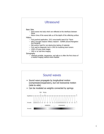
UltrasoundBasic Idea– Send waves into body which are reflected at the interfaces betweentissue– Return time of the waves tells us of the depth of the reflecting surfaceHistory– First practical application, 1912 unsuccessful search for Titanic– WW II brought massive military research - SONAR (SOund NavigationAnd Ranging)– Mid-century used for non-destructive testing of materials– First used as diagnostic tool in 1942 for localizing brain tumors– 1950’s 2D gray scale images– 1965 or so real-time imagingSonography– relatively portable, inexpensive, and safe so is often the first choice ofa medical imaging method where feasibleSound waves Sound wave propagate by longitudinal motion(compression/expansion), but not transverse motion(side-to-side) Can be modeled as weights connected by springs1
Ultrasonic Waves and properties Mechanical waves are longitudinal compression waves“Ultrasound” refers to frequencies greater than 20kHz, the limit ofhuman hearingFor Medical imaging typically 100 Times higher frequency than audibleby human typically 2 to 20 MHzTransmission and Reflection2
Propagation of ultrasound waves in tissueScattering Specular reflector is a smooth boundary between media (conventional view of reflections Acoustic scattering arises from objects that are size of wavelength or smaller Most organs have characteristic structure that gives rise to defined scatter “signature”Specular - echoes originating from relatively large, regularly shaped objects withsmooth surfaces. These echoes are relatively intense and angle dependent. (i.e.valves) - Reflection from large surfacesScattered - echoes originating from relatively small, weakly reflective, irregularlyshaped objects are less angle dependant and less intense. (i.e. blood cells) Reflection from small surfacesBasic Idea Along each line we transmit a pulse and plot thereflections that come back vs time3
The Speed of Sound The compressibility κ and density ρ of a material,combined with the laws of conservation of mass andmomentum, directly imply the existence of acousticwaves Ultrasound waves travel at a speed of sound c, givenby1c !"Variations in Speed Speed of sound fordifferent materialsc 1!"4
Physics of Acoustic Waves Three dimensional in nature and depend on time Whatever the physical quantities that are used to describe thesound waves, they must depend upon three spatial variables, x,y, z, and time, t Particle displacement u(x, y, z, t) associated with thecompression and expansion of the acoustic wave Particle velocity v(x, y, z, t) Acoustic pressure p(x, y, z, t), which is zero if there is no waveFor longitudinal waves, it is straightforward to relate the acousticpressure to the underlying particle velocityp vZwhere Z ρc is called the characteristic impedance– This is a like V IR– Note that v ! cVariations in Speed and Impedance Speed of soundfor differentmaterialsc 1!" Impedancerelating pressureto particlevelocityp vZZ !c !"5
Wave Equation The acoustic pressure p must satisfy the three-dimensional waveequation" !2!2!2 %1 !2 p(x, y, z,t) !x 2 !y 2 !z 2 ' p(x, y, z,t) c 2!t 2#& For a plane wave traveling in the z-direction thus reduces to!2 p(z,t) 1 !2 p(z,t) 2!z 2c!t 2 An example solution is, p(z,t) cos k(z ! tc)which has cyclic frequency (in Hertz) off kc2!which also leads to the important relationf c!Propagation of ultrasound waves in tissue Ultrasound imaging systemscommonly operate at 3.5MHz, which corresponds to awavelength of 0.44 mmwhen c 1540 m/s.Refraction When a wave passes fromone medium to another thefrequency is constant, andsince c changes then somust the wavelengthc! fMaterial 1Material 2since λ2 λ1we have c2 c16
Propagation of ultrasound waves in tissue Bending of waves from onemedium to another is 'refraction' Follows Snell’s Lawsin !i sin !r sin !t c1c1c2incidenttransmittedreflectedsince λ2 λ1we have c2 c1and θ2 θ1Total Internal Reflection Since λ2 λ1 in this case, we have c2 c1 and θ2 θ1 There can be a 'critical' incident angle θ1 θC where θ2 90deg, i.e. there is no transmitted wave. In that case there is'total internal reflection of the wave7
Attenuation of ultrasound waves in tissueAttenuation is the term used to account for loss of wave amplitude (or ‘‘signal’’)due to all mechanisms, including absorption, scattering, and mode conversionThe model of attenuation is phenomenological, meaning it agrees well in practicebut is not easily supported by theoryWe model amplitude decay asA(z) A0 e! µ A zwhere µA is called the amplitude attenuation factor and has units cm 1Since 20 log10 (A(z)/A0) is the amplitude drop in decibels (dB), it is useful todefine theattenuation coefficient α as! 20 log10 (e) " µ A # 8.7 µ AThe absorption coefficient of a material is generally dependent on frequency f,and a good model for this dependency is ! af bThe rough approximation that b 1 is often usedAttenuation of ultrasound waves in tissueAssuming b 1A(z, f ) A0 e! afz /8.78
Time-Gain Compensation Depth of signal is related to reflectiontime, so as time progresses, the signalwill be increasingly attenuatedTime-dependent attenuation causessevere signal loss if not compensatedAll systems are equipped with circuitrythat performs time-gain compensation(TGC), a time-varying amplificationIn practice, most systems haveadditional (frequency dependent) slidepotentiometers, which allow the gain tobe determined interactively by theoperator. This permits the user tomanually adapt the system to specialcircumstances requiring either more orless gain so that subtle features can beseen in the images. Generation of Ultrasound A 'transducer' converts energy from one form to anotherThe “Piezoelectric effect” was described 1880 Pierre and Jacques CurieLead zirconate titanate, or PZT, is the piezoelectric material used in nearly all medical ultrasoundtransducersIt is a ceramic ferroelectric crystal exhibiting a strong piezoelectric effect and can be manufactured innearly any shapeThe most common transducer shapes are the circle, for single crystal transducer assemblies, and therectangle, for multiple transducer assemblies such as those found in linear and phased arrays9
Beam Pattern Formation Simple Field Pattern ModelFresnel regionGeometric approximationFraunhofer (or far field) regionApproximate field pattern for a focused transducer10
Collect the EchoTransducers11
Phased-Array concept fortransmission and receptionPlanardelayed pulsesFocusedarray ofpiezoelectric crystalsgenerated wave (transmission)sensitive region (reception)Transducer Arrays12
Array Transducers Linear arrays(composed of 256 to 512 discrete transducerelements) ( 15 to 20 adjacent elementssimultaneously activated sequentially acrosssurface to sweep FOV) Phased array transducers(composed of 64, 128, or 256 elements) (phase delayvaried to sweep across FOV)Side-lobes Focused arrays typically have larger 'sidelobes' ofsignal power for transmission and sensitivity forreception13
(Amplitude) A-Mode Along each line we transmit a pulse and plot the reflections that comeback vs timeUnfortunately, it is very difficult to associate a precise physical meaningwith the received signal amplitude vs timeUltrasonic Imaging Modes14
Ultrasonic Imaging ModesEcho Display Modes: A-mode (amplitude): display of processedinformation from the receiver versus time– Speed of sound equates to depth– (only used in ophthalmology applications now) B-mode (brightness): Conversion of A-modeinformation into brightness-modulated dots M-mode (motion): uses B-mode information todisplay the echoes from a moving organA-Mode ExampleTransmission pulse in red, reflected waves in blue15
Forming an Image The amplitude values are converted to brightness along a lineand displayed on a screen The line direction is swept across an angular range, eithermechanically or electromagnetic beamformingbeam sweepForming Clinical ImagesProbe locationsTwo common clinical ultrasound examinations(L) an echocardiogram showing the four chambers of the heart(R) fetal ultrasound, showing a normal fetus at the secondtrimester of gestation.16
Complete SystemAcquisition and Recon Time For external imaging: each line corresponds to 20cm.–––––Velocity of sound in soft tissue is 1540 m/s.Travel distance from and to transducer 40 cmAcquisition of line takes 260 µsTypical image has 120 lines for total time of 31 ms.Images reconstructed in real time So can have temporalresolution of 30 Hz (30 images a second) Modern scanners collect multiple scan lines simultaneouslyusually frame rates of 70-80 Hz17
Clinical Uses - Cardiac trium B-mode image of a normal heartExample of M-Mode below 2D B-mode Image18
Clinical Uses - Neonatal B-mode image of a fetus. The dark region is theuterus, which is filled with fluidDoppler Imaging1.Continuous Wave (CW) Doppler:–2.Pulsed Wave (PW) Doppler:–3.Continuous sinusoidal wave transmitted with one crystal and reflectedwave received with second crystalPulsed waves transmitted at constant pulse repetition frequency and onlyone sample as function of time is collectedColor Flow (CF) imaging:19
Doppler ImagingDoppler ImagingColor Flow (CF) imaging: Doppler equivalent of B-mode scan several pulses instead ofone are transmitted/received along each lineCalculates phase shift between two subsequent pulsesVelocity information in color is superimposed on anatomical grayscale imageRed - flow towards transducerBlue - flow away from transducer20
3D Image FormationReordering of the knownslice locations providessurface-shaded, wiremesh, MIP, or otherrenditions of the anatomyComparing 2D to 3D US21
Dangers of Ultrasound very minimal in comparison to other methods development of heat - tissues or water absorb the ultrasoundenergy which increases their temperature locallyformation of bubbles (cavitation) - when dissolved gasescome out of solution due to local heat caused by ultrasoundhigh intensity systems actually used for therapy Some Ultrasound Uses(short list) Obstetrics and Gynecology– measuring the size of the fetus to determine the due date–checking the sex of the baby (if the genital area can be clearly seen)– checking the fetus's growth rate by making many measurements over time– detecting ectopic pregnancy, the life-threatening situation in which the baby isimplanted in the mother's Fallopian tubes instead of in the uterus– determining whether there is an appropriate amount of amniotic fluid cushioning thebaby– monitoring the baby during specialized procedures - ultrasound has been helpful inseeing and avoiding the baby during amniocentesis (sampling of the amniotic fluidwith a needle for genetic testing). Years ago, doctors use to perform this procedureblindly; however, with accompanying use of ultrasound, the risks of this procedurehave dropped dramatically.– seeing tumors of the ovary and breast Cardiology–seeing the inside of the heart to identify abnormal structures or functions–measuring blood flow through the heart and major blood vessels Urology–measuring blood flow through the kidney–seeing kidney stones–detecting prostate cancer early22
Breast Cancer Example Not same dimension scale In US we terms like hypoechoic or hyporeflective for lowintensity regions, and hyperechoic or hyperreflective for highintensity regionsDynamic Fetal Ultrasound Imaging23
Brain scan exampleNormalFluid from intraventricular hemorrhage24
–Mid-century used for non-destructive testing of materials –First used as diagnostic tool in 1942 for localizing brain tumors –1950’s 2D gray scale images –1965 or so real-time imaging Sonography –relatively portable, inexpensive, and safe so is often the first choi

