Transcription
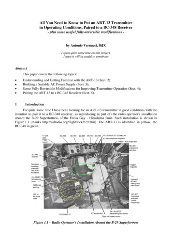
All You Need to Know to Put an ART-13 Transmitterin Operating Conditions, Paired to a BC-348 Receiver- plus some useful fully-reversible modifications -by Antonio Vernucci, I0JXI spent quite some time on this project.I hope it will be useful to somebodyAbstractThis paper covers the following topics: 1Understanding and Getting Familiar with the ART-13 (Sect. 2);Building a Suitable AC Power Supply (Sect. 3);Some Fully-Reversible Modifications for Improving Transmitter Operation (Sect. 4);Pairing the ART-13 to a BC-348 Receiver (Sect. 5).IntroductionFor quite some time I have been looking for an ART-13 transmitter in good conditions with theintention to pair it to a BC-348 receiver, so reproducing (a part of) the radio operator's installationaboard the B-29 Superfortress of the Enola Gay - Hiroshima fame. Such installation is shown inFigure 1.1 (thanks http://aafradio.org/flightdeck/b29.htm). The ART-13 is identified in yellow, theBC-348 in green.Figure 1.1 – Radio Operator's Installation Aboard the B-29 Superfortress
You can find a lot of general and detailed information about the ART-13 on the Internet, so Iwill here limit myself to discussing the essential things that you must know if you wish toknowledgeably set-up and operate the transmitter. You can so avoid the fatiguing task of reading verythick instruction or maintenance books, with hundreds of pages most of which deal with issues oflittle interest for amateur radio. Tracing the bit of information you need is sometimes really anuisance!I here assume that your ART-13 is perfectly functional. In case of problems, for fixing it therewill be no escape to reading the ART-13 reference documents that you can find on BAMA at webpage At this regard please note that: the 400-page book A NAVWEPS 16-30 ART13-5, Handbook, Maintenance Instructions, AircraftRadio Equipment, AN/ART-13, Oscillator O-17/ART-13A (file ART-13.pdf) is verycomprehensive and contains all information you need to thoroughly understand the ART-13;the other two available books, namely:- the Handbook, Operating Instructions for Radio Transmitting Sets, AN/ART-13, AN/ART13A, AN/ART-13B and Navy Models ATC ATC-1 (file ART13-1.pdf);- and the Handbook, Maintenance Instructions, Radio Transmitting Set AN/ART-13A (fileART13-2.pdf);are, in my opinion, not as useful as the former one.It is not uncommon to find ART-13s built in France under licence. Those units bear markings inFrench. The correspondence between the English and the French terms is shown in Annex 1.2Understanding and Getting Familiar with the ART-132.1An OverviewWARNING: LETHAL VOLTAGES ARE PRESENT IN THE ART-13. IF YOU ARE NOT ANEXPERIENCED TECHNICIAN, YOU ARE ADVISED GIVING UP THIS PROJECTThe ART-13 is a radio transmitter capable of delivering more than 100 W of RF power andoperating in the range 2.0-18.1 MHz. So, it covers the 80-, 40-, 30-, 20- and 17-meter amateur radiobands though, in practice, In my case, I have been unable to get a reasonable output power at theextreme upper edge of the band (i.e. around 18.1 MHz), because of the low RF power tube gridcurrent that is obtained (even re-adjusting the frequency multipliers tuning). The transmit frequency isdetermined by an accurate and stable variable frequency oscillator that is called HFO (HighFrequency Oscillator). The ART-13 can also work in the 200-1,500 kHz range if also equipped withthe optional LFO (Low Frequency Oscillator), but that band is of modest interest for amateur radiopurposes. The ART-13 works in the following modes: VOICE: this is the classical AM (Amplitude Modulation) mode, i.e. a carrier accompanied byboth the upper and the lower sideband. The RF power tube is plate- and screen-grid modulated,and the modulation percentage that can be obtained is very high (90% according to the ART-13books). You may either use a carbon or a dynamic microphone (selectable by means of aninternal switch);CW (Continuous Wave): this is the classical mode used to transmit Morse code. The ART-13works in the so-called “full break-in” mode, this meaning that the transmitter goes on transmitevery time the Morse key is pressed and reverts back to receive when the key is released. Suchswitching is done by a massive and noisy relay that steadily chatters at the Morse code rhythm.A modification for avoiding this nuisance is described in Sect. 4;MCW (Modulated Continuous Wave): this is an alternative way to transmit Morse code whichcan be received by an ordinary AM receiver not having a BFO (Beat Frequency Oscillator). The
only difference between MCW and CW is that, with MCW, the transmitted carrier is modulatedby a 1,000-Hz tone. Like CW, the MCW carrier is only radiated when the Morse key is pressed.The ART-13 is designed to work in conjunction with short wire antennas typically showing ahigh reactance and a resistance lower than 50 ohm (they recommend to use, for testing purposes, adummy load consisting of a 4 ohm resistor with a 100 pF capacitor in series). Nevertheless it canwork with standard 50-ohm antennas (though a modification is needed for operating on the low partof the spectrum, see Sect. 4).The ART-13 is powered by a big and noisy dynamotor running on 28 VDC (various dynamotorversions exist, but they are interchangeable) and providing the necessary high voltages (400 VDC,1,150 VDC). Using instead an home made AC power supply (see Sect. 3) is highly recommended.The ART-13 has an “Autotune” feature that, when desired, automatically sets the fivetransmitter tuning knobs in one of ten stored patterns. This is just a “mechanical memory” operatedby a built-in motor that turns the knobs, and has then nothing to do with the modern automaticantenna tuners that instead match the transmitter to the actual antenna impedance.The ART-13 has provisions to control an external receiver. On receive, an internal relay divertsthe antenna to an external terminal, and shorts two pins of external plug receptacle that can be used toclose the receiver ST-BY control (to do this, just connect the receiver ST-BY to pins 23 and 24 of theU-8/U male connector plug mating the ART-13 J106 27-pin plug receptacle). The ART-13 howeverlacks the “Spot” command, so it does not allow to comfortably zero-beat - at low power - the transmitfrequency on the receive frequency. A modification for having that possibility is described in Sect. 4.Lastly, the ART-13 offers a facility (“CFI circuit”), permitting to precisely calibrate the transmitfrequency against a set of reference frequencies (spaced 100- to 600-kHz, depending on the band)derived from an internal 200-kHz crystal.2.2What You Actually NeedA number of optional accessories exist for the ART-13, which are of very little use for amateurradio purposes. In summary what you will really need is just: the ART-13 itself. Note: whatever you will find mounted in position 12 of Figure 2.1 (whetherthe LFO oscillator, or the dummy LFO, or the crystal oscillator) it does not matter;a power supply, either the matching dynamotor or an AC power supply to be built on purpose(see Sect. 3).With regard to the interconnect cables: if you use a dynamotor, try to obtain the original dynamotor-to-battery and dynamotor-to-ART13 cables. If unavailable, you shall build:- a 2-wire battery cable bearing a female U-10/U 3-pin connector plug on the dynamotor end;and a 10-wire power cable connecting the dynamotor to the ART-13 J108 10-pin plugreceptacle (the bigger of the three receptacles on the left upper side of the transmitter). Thepower cable shall bear a female U-7/U 10-pin connector plug on the ART-13 end and a maleU-9/U 10-pin connector plug on the dynamotor end;if you instead use an AC power supply, you shall just build a 10-wire power cable (see above),bearing a female U-7/U 10-pin connector plug on the ART-13 end.You may want to also build the receiver ST-BY cable. This must bear a U-8/U 27-pin maleconnector plug mating the ART-13 J106 27-pin plug receptacle (use pins 23 and 24 for ST-BY).The ART-13 connector plugs are hard to find and, when found, they are usually ratherexpensive. I bought mine at http://www.fairradio.com/ but they occasionally also appear on eBay.
2.3The Front Panel ControlsIn Figure 2.1, showing the ART-13 front panel, the available controls are individually numberedfor easier identification.Figure 2.1 – ART-13 Front PanelIn the following, the functions of the various controls are described with regard to Figure 2.1numbering.No. 1)This control, referred to as “CONTROL A” and marked “HIGH FREQUENCY TUNING COARSE” is the bandswitch of the frequency generation system (comprising the HFOoscillator and two multiplier stages). It has twelve useful positions (position no. 13 engagesthe LFO oscillator for low frequencies below 1,500 kHz, in place of the HFO) that also bearindications of the frequency range, corresponding to those shown Table 2.1.CONTROL APosition123456789101112Transmitter outputfrequency range2.000 - 2.400 MHz2.400 - 3.000 MHz3.000 - 3.600 MHz3.600 - 4.000 MHz4.000 - 4.800 MHz4.800 - 6.000 MHz6.000 - 7.200 MHz7.200 - 9.000 MHz9.000 - 10.800 MHz10.800 - 12.000 MHz12.000 - 14.400 MHz14.400 - 18.100 MHzTable 2.1 – ART-13 Bandswitching
No. 2)No. 3)No. 4)No. 5)Despite CONTROL A acts as a switch, it can be turned in continuous manner. If the positionindicator is not precisely aligned with any of the triangles marked on the knob skirt, aninterlock switch disables the transmitter. Adjusting CONTROL A is fairly critical; you arethen advised to always verify the presence of grid current in the RF power tube.This control, referred to as “CONTROL B” and marked “HIGH FREQUENCY TUNING FINE” sets the HFO oscillator frequency and then ultimately, in conjunction withCONTROL A, the transmit frequency. CONTROL B is a multi-turn control whose positionis defined as XXYY.Y, where XX is the number read on the round indicator No. 3 (ranging00 to 20) and YY.Y is the number read on the CONTROL B knob skirt (ranging 00.0 to99.9). The correspondence between the CONTROL A / CONTROL B positions and thetransmit frequency is shown in tables appearing in any ART-13 reference book (see Sect. 1).See control No. 2.This control marked “CORRECTOR” shifts a movable position indicator that serves asreference for the CONTROL B scale (see control No. 2), so as to have the indicatedfrequency (almost) coincident with real frequency. This control is to be operated whencalibrating the HFO frequency (CFI circuit ) on the closest reference frequency.This control, referred to as “CONTROL C” and marked “ANTENNA TUNING - COARSE”is the bandswitch of the RF output network. It has twelve useful positions (position 13 is ofno practical use) and, similarly to CONTROL A (see control No. 1), can be turned incontinuous manner despite it acts as a switch (again the position indicator must be preciselyaligned with any of the triangles marked on the knob skirt, otherwise an interlock switchdisables the transmitter). Differently from CONTROL A, the CONTROL C position is notprecisely bound to a frequency range, it also depending on antenna impedance. In Tables 2.2and 2.3, some examples of CONTROL C settings are shown together with those ofCONTROL D (see control. No. 6) and CONTROL E (see control No. 7).AMATEUR BANDS - on a 50-ohm dummy loadCONTROL CCONTROL DCONTROL E6801341116112123570126580Frequency(*) 3.520 MHz(**) 7.020 MHz10.120 MHz14.020 MHzTable 2.2 – Typical Adjustments for Amateur Installations(*) with a 2,000-pF capacitor in parallel to the antenna(**) with a 330-pF capacitor in parallel to the antennaGENERAL COVERAGE - on a typical wire antennaFrequencyCONTROL CCONTROL DCONTROL E2.270 MHz2100252.739 MHz455653.405 MHz601004.110 MHz6551334.539 MHz6821485.479 MHz7531526.809 MHz10601008,217 MHz11404810.213 MHz116013312.325 MHz118013413.617 MHz118814416.434 MHz1281200Table 2.3 – Adjustments for a Typical Wire Antenna (20' to 60' long)
No. 6)No. 7)No. 8)No. 9)No. 10)No. 11)No. 12)No. 13)No. 14)It should be noted that:- when the CONTROL C position is in between 1 e 7, the RF output network isconfigured as an “L-network”, with series-L and parallel-C on the RF power tube side;- when the CONTROL C position is in between 8 e 13, the RF output network isconfigured as a “Pi- network”.This control, referred to as “CONTROL D” and marked “ANTENNA TUNING - FINE”,varies the inductance of a variometer (variable inductor) part of the RF output network:- when the CONTROL C position is in between 1 e 7 (L-network), CONTROL D variesthe series inductance of the network, so acting as the loading control;- when the CONTROL C position is in between 8 e 13 (Pi-network), CONTROL D alsovaries the series inductance of the network, now acting as the tuning control;The CONTROL D position is marked 0 to 100.This control, referred to as “CONTROL E” and marked “ANTENNA LOADING” varies thecapacitance of a variable capacitor which belongs to the RF output network::- when the CONTROL C position is in between 1 and 7 (L-network), CONTROL E variesthe parallel capacitance of the network at the RF power tube side, so acting as the tuningcontrol;- when the CONTROL C position is in between 8 e 13 (Pi-network), CONTROL E variesthe parallel capacitance of the network at the antenna side, so acting as the loadingcontrol.The CONTROL E position is marked 0 to 200, with a discontinuity at position 100. Itshould be noted that, in the range 0-100, a fixed capacitor is placed in parallel to the variablecapacitor, whilst in the range 100-200 the fixed capacitor gets disconnected. Capacitancevalues are chosen so that the capacitance variation has no discontinuity across the whole 0200 range.The KEY jack accepts a standard 2-pole 1/4” plug (type PL-55) for connection to a MorseKey.The SIDETONE 1 jack (J104) accepts a standard 2-pole 1/4” plug (type PL-55) forconnection to a 600-ohm earphone or speaker. This is used for both the CW sidetone and forthe HFO calibration (by means of the CFI circuit). The sidetone level can be adjusted bymeans of a switch located beneath the hinged panel No. 10 (unlock and raise it). Thesidetone signal is also available at pin 27 of the U-8/U 27-pin male connector plug thatmates the ART-13 J106 plug receptacle.The SIDETONE 2 jack (J105), which also accepts a 2-pole 1/4” plug (type PL-55) is onlyconnected to pin 26 of the above mentioned U-8/U 27-pin male connector plug.Beneath the hinged panel holding the tuning chart one can find the microphone type selector(see control No. 11) and the sidetone level adjustment (see control No. 9) consisting of asix-position switch determining the sidetone output level (ranging from 0.5 V to 18 V).The MICROPHONE jack accepts a standard 3-pole 0.206” plug (type PL-68) for connectionto a microphone with Push-To-Talk (PTT) command. Selection between a carbon ordynamic microphone is done through an internal switch located beneath the hinged panel(see control No. 10).The ART-13 has room for hosting an LFO oscillator (type O-16 or O-17) for operations inthe 200-1,500 kHz range or a crystal oscillator (type CDA-T). Both of them are of littleinterest for amateur purposes. Simply disregard them. Some ART-13s are alternatelyequipped with a dummy LFO (just containing a resistor emulating the tube filament).The TEST switch serves to temporarily put the ART-13 in the transmit mode. This canalternately be obtained by pressing the microphone PTT or the Morse key, or closing thethrottle switch (see control No. 14).The throttle switch, marked TS, was used by the pilot to put the ART-13 in the transmitmode when speaking into a lip or mask microphone. No interest for amateur radio.
No. 15) The LOCAL-REMOTE switch serves to command the transmitter from a remote location,using the Control Unit C87. Simply leave it on LOCAL and forget about it.No. 16) The Autotune switch permits to preset CONTROL A, CONTROL B, CONTROL C,CONTROL D and CONTROL E on one of ten stored settings (channel 1 . 10). In theMANUAL position the Autotune feature is disabled. The L. FREQ position serves for lowfrequencies (below 1,500 kHz);No. 17) This switch permits to select:- the CALIBRATE mode: this is just used for calibrating the HFO frequency on theclosest reference frequency produced by the CFI circuit;- the TUNE mode: this is used for tuning purposes. The transmitter operates at lowerpower than nominal;- the OPERATE mode: this is the normal full-power mode.No. 18) The EMISSION switch has four positions, namely:- position OFF: transmitter inoperative (filaments off);- position VOICE: for AM operation (filaments lit);- position CW: for Morse code operation (filaments lit);- position MCW: for Morse code operation on modulated carrier, see Sect. 2.1 (filamentslit).No. 19) The ANTENNA CURRENT meter, of the thermocouple type, measures the current flowinginto the antenna. It has a full-scale reading of 5 A (in reality it has a 250 mA thermocoupleloosely coupled to the antenna current).No. 20) The multi-funcion meter having an arbitrary 0-200 scale shows, depending on the positionof the meter switch (see control No. 21):- in position BATTERY VOLTAGE (coinciding with filaments voltage): the 28 VDCcoming from the dynamotor (54 V full scale);- in position P.A. GRID: the RF power amplifier grid current (about 18 mA full scale);- in position P.A. PLATE: the sum of the RF power amplifier and the final audio poweramplifier tubes plate currents (about 300 mA full scale).No. 21) See control No. 202.4The Side Terminals and Plug ReceptaclesThe terminals and plug receptacles located on the left ART-13 panel are identified in Figure 2.2.Figure 2.2 – ART-13 Left Panel
The functions of the various terminals are itemized below:A)B)C)D)E)ANT. terminal (J109), This is the RF output after the internal antenna relay.COND terminal (J118). This is the RF output before the internal antenna relay, which permitsadding an external capacitor to the output of the RF output network so as to improve antennamatching (see Sect. 4).GROUND terminal (J113). Self explanatory.LOAD COIL (J117). This terminal is directly connected to the RF power tube plate (onlyenabled when operating on low frequencies below 1,500 kHz. Probably of little interest foramateur purposes).RECEIVER terminal (J110). This provides the antenna signal to an external receiver, after theinternal antenna relay.For what concerns the multi-pin receptacles, connector plugs U-7/U and U-8/U were alreadydiscussed in Sect. 2.2, while the U-11/U connector plug mating the ART-13 J107 3-pin plugreceptacle is of no practical interest for amateur purposes.2.5Initial ChecksTo initially check the transmitter proceed as follows: set the EMISSION switch to OFF;put the transmitter on LOCAL, MANUAL, TUNE;make all required connections (power cable to dynamotor or AC supply, dynamotor to itsbattery or power supply, antenna, microphone, key);consistently set the microphone type switch beneath the hinged panel (control No. 10 in Figure2.1);check that the CONTROL A and CONTROL C position indicators are precisely aligned withany of the triangles marked on the knobs skirt.When turning the EMISSION switch from OFF to VOICE, do not worry if you seeCONTROL A, CONTROL B, CONTROL C, CONTROL D and CONTROL E rotating for sometime. After a while they will stop. You should see all tubes filaments lit, while the dynamotor shouldNOT start. If some filaments do not get lit, firstly make it sure that all tubes are fully seated into theirsockets. If the problem persists, check the tube filaments one by one. Remember that several tubeshave filaments wired in series, and that one bad tube can then cause the filament of a good tube not tolit. Once all filaments are lit, you can check that filament voltage is OK reading the BATTERYVOLTAGE on the multi-function meter.At that point briefly press the microphone PTT, and you should then hear the dynamotor startingand see some P.A. PLATE current on the multi-function meter, as well as some P.A. GRID current.Whistling into the microphone, you should see the P.A. PLATE current increasing (due to thecontribution of the final audio power tubes that operate in class B).At that point release the PTT, and turn the EMISSION switch to CW. The dynamotor shouldthen run continuously. Pressing the key, you should see about the same amount of P.A. PLATEcurrent and P.A. GRID current of when operating in VOICE.Lastly release the key, and turn the EMISSION switch to MCW. The dynamotor shouldcontinue to run. Pressing the key, you should see a higher P.A. PLATE current than when operatingin CW.Having successfully completed the above steps means that your ART-13 is basically functional.You can then proceed to tune it on your preferred frequency and verify the output power as well as
the modulation quality. You may also consider to undertake the transmitter re-adjustment procedure(see the books), but this is only recommended if obtained performances are worse than expected.Just a few words on the Autotune feature. If you are not interested in it, just put the switch onMANUAL and forget about it. Otherwise please note the following: 2.6the locking bars of the five knobs must all stay always tightened, also when you adjust thecontrols position manually (this is only possible in MANUAL). Failure to do so will result inloss of the Autotune channels setting (i.e. you will loose the stored controls positions);the only occasion in which you shall temporarily loosen the knob locking bars is when you wishto change the setting for one of the available channels (e.g. for channel #1). In that case:- put the switch on channel #1 and wait for the Autotune motor to stop;- loosen the five knobs locking bars;- manually turn the controls as desired for channel #1 (normally for correctly tuning thetransmitter on the intended frequency). When doing this, you may rotate the control eitherdirections, but the final setting of each control shall be approached clockwise. A way to besure of doing things correctly: turn the control as desired and note its position; then rotate the control counterclockwsie one eighth turn; again turn the control back to the noted position, approaching it clockwise;- at that point tighten all the knobs locking bars (paying care not to turn the controls), and thecontrols setting will now be stored for channel #1;.if, after switching to any other channel, you go back to channel #1 the five controls will returnto the positions stored for that channel. At that point the controls are stuck and you will not beable to turn them manually. For turning the controls manually you must be in MANUAL.Abridged Theory of OperationThe ART-13 operation can be basically described with regard to Figures 2.3 and 2.4, where themain constituting elements are individually numbered.Figure 2.3 – ART-13 Audio, CFI, HFO and Frequency Multipliers Compartment
Figure 2.4 – ART-13 RF and Modulator CompartmentThe power circuits Filaments: when the EMISSION is turned from OFF to VOICE or CW or MCW, relay K2102(located inside the dynamotor) delivers 28 VDC (i.e. the same voltage that feeds the dynamotor)to the tubes filaments. These are wired in series / parallel, with balancing resistors whererequired. Only the power amplifiers (i.e. the type- 813 RF power tube and the type- 811 finalaudio power tubes) are of the direct heating type; so allow at least one minute between turningthe EMISSION switch and operating the transmitter. The correct filament voltage can bechecked on the multi-function meter, putting the switch in the BATTERY VOLTAGE position.High voltage: the ART-13 requires two distinct high voltages, that is 1,150 VDC @ 300 mA forthe power tubes plates and 400 VDC @ 225 mA to power everything else. Accordingly thedynamotor has two windings, a 400 VDC winding and a 750 VDC winding that is put in serieswith the 400 VDC one, so producing 1,150 VDC. Inside the dynamotor, relay K2106 reducesthe high voltage from 1,150 VDC down to 750 VDC when flying above 25,000 feet, to preventflashover; this is clearly of no interest for amateur usage. When the multi-function meter switchis in the P.A. PLATE position, the meter measures the current flowing through the 750 VDCwinding, so effectively measuring the total power tubes (RF audio) plate current in anycondition. It should lastly be noted that, when in CW or MCW, the dynamotor runscontinuously; instead, when in VOICE, the dynamotor only runs when the transmitter isswitched on transmit (e.g. by pressing the microphone PTT) or is put in CALIBRATE.The RF circuits The HFO oscillator (see item 1 in Figure 2.3): this is a type-837 tube that oscillates either inrange 1.000-1.200 MHz or range 1.200-1.510 MHz. The actual operating range depends on theposition of CONTROL A (upon command of switch S101). The HFO is activated (groundingits cathode through resistor R131) when the transmitter is put on transmit and the CONTROL Aposition indicator is precisely set on any of the triangles marked on the knob skirt (uponcommand of switch S114).The high-frequency frequency multipliers (see item 2 in Figure 2.3): there are two frequencymultiplier stages, each equipped with a type-1625 tube. The first multiplier, which multiplies by
a factor 2, 3 or 4 depending on the position of CONTROL A, is always inserted in the circuit.The second multiplier, which multiplies by a factor 3, is inserted in the circuit (by S115) onlywhen needed, depending on the position of CONTROL A. The multipliers are only poweredwhen the transmitter is in OPERATE or TUNE. Table 2.4 shows the HFO and frequencymultipliers operating parameters.Transmitter outputfrequency2.000 - 2.400 MHz2.400 - 3.000 MHz3.000 - 3.600 MHz3.600 - 4.000 MHz4.000 - 4.800 MHz4.800 - 6.000 MHz6.000 - 7.200 MHz7.200 - 9.000 MHz9.000 - 10.800 MHz10.800 - 12.000 MHz12.000 - 14.400 MHz14.400 - 18.100 MHzCONTROL Aposition123456789101112HFO frequency range1.000 – 1.200 MHz1.200 – 1.510 MHz1.000 – 1.200 MHz1.200 – 1.510 MHz1.000 – 1.200 MHz1.200 – 1.510 MHz1.000 – 1.200 MHz1.200 – 1.510 MHz1.000 – 1.200 MHz1.200 – 1.510 MHz1.000 – 1.200 MHz1.200 – 1.510 MHzFrequencymultiplierFirst onlyFirst onlyFirst onlyFirst onlyFirst onlyFirst onlyFirst secondFirst secondFirst secondFirst secondFirst secondFirst secondOverall multiplicationfactor2233442*3 62*3 63*3 93*3 94*3 124*3 12Table 2.4 – ART-13 Frequency Generation Approach The RF power amplifier (see item 3 in Figures 2.3 or 2.4): this is a type-813 beam pentodeoperating in class C. The tube has no fixed bias; so, in absence of the drive signal, the platecurrent gets very high, to the extent of exceeding the rated plate dissipation. You are thenadvised to always check the presence of grid current on the multi-function meter. Voltage isapplied to the tube screen only when the transmitter is in the transmit mode. The poweramplifier is both plate- and screen-modulated by means of two separate secondary windings ofthe modulation transformer (see item 4 in Figure 2.4). The plate winding is shorted by relayK103 when operating CW. The RF power amplifier plate is connected to the antenna via the RFoutput network and the vacuum contact S116 (see item 5 in Figure 2.4). The RF networkconfiguration (either an L-network or a Pi-network) depends on the setting of CONTROL C(see Sect. 2.3), which actuates switches S113A . S113H. You are again reminded that theCONTROL C position indicator must be precisely set on any of the triangles marked on theknob skirt (otherwise transmission is disabled by switch S113D). In addition to what written inSect. 2.3 with regard to controls No. 5 and No. 6, the following should be noted:- L-network configuration (CONTROL C position in between 1 and 7): the parallel capacitance (on the RF power tube side) consists of variable capacitorC125 (activated by CONTROL E), with fixed capacitor C124 switched in parallel (byS113A) when CONTROL E position is in range 0-100; the series inductance consists of a variometer (actuated by CONTROL D) in series toa fixed coil (L112) and to a multi-tapped coil (L113, see item 6 in Figure 2.4) havingmaximum inductance when CONTROL C is in position 1 and zero inductance (i.e. bypassed) when CONTROL C is in position 7. Tap switching is done by S113C;- Pi-network configuration (CONTROL C position in between 8 and 13): the parallel capacitance (on the RF power tube side) is represented by variouscombinations of fixed capacitors (C122, C129 e C130) that are switched in by S113F,S113G e S113H, as a function of CONTROL C position. Total capacitance decreaseswhen increasing the operating frequency;
the parallel capacitance (on the antenna side) consists of variable capacitor C125(activated by CONTROL E), with fixed capacitor C124 switched in parallel whenCONTROL E position is in range 0-100;the series inductance consists of a variometer (actuated by CONTROL D) in serieswhich a fixed coil (L112), to which a second fixed coil (L114) is put in parallel (byS113E) when CONTROL C is in position 13.It should be noted that, when operating on low frequencies (200-1,500 kHz) the RF power tubeplate is directly brought to the exterior (on terminal D through K105, see Sect. 2.4) with nooutput network at all.Figure 2.5 shows the RF output network in the L and Pi configurations.Figure 2.5 – ART-13 RF Output Network ConfigurationsThe audio circuits The Audio Amplifier Sidetone Amplifier assembly (see item 7 in Figure 2.3), comprising:- a low-level audio amplifier (a 12SL7 twin-triode) that amplifies the microphone signal(when in VOICE) or the 1000-Hz sidetone signal produced by the audio oscillator (when inCW or MCW) or the CFI detector output (when in CALIBRATE). The selection ofmicrophone type (either carbon or dynamic) is done by switch S201 located beneath thehinged panel (see Sect. 2.3, control No. 10). In the carbon microphone position a voltage of1.57 V is required to obtain 90% modulation, while in the dynamic microphone position avoltage of 16 mV is sufficient;- an intermediate au
- the Handbook, Operating Instructions for Radio Transmitting Sets, AN/ART-13, AN/ART-13A, AN/ART-13B and Navy Models ATC ATC-1 (file ART13-1.pdf); - and the Handbook, Maintenance Instructions, Radio Transmitting Set AN/ART-13A (file ART13-2.pdf);