Transcription
2018 JETIR September 2018, Volume 5, Issue 9www.jetir.org (ISSN-2349-5162)MINIMIZATION OF SINK MARK DEFECTS IN INJECTIONMOLDING PROCESSNaveen Reddy Pothula1, S.Vamshi Krishna2, K.Charantej3, Bodugam Siddartha41Assistant Professor in the Department of Mechanical Engineering VITS (N6),Karimnagar, Telangana, India-505001, reddy.n52@gmail.com2Assistant Professor in the Department of Mechanical Engineering VITS (N6),Karimnagar, Telangana, India-505001, sravas.34@gmail.com3Assistant Professor in the Department of Mechanical Engineering VITS (N6),Karimnagar, Telangana, India-505001, charantej.kalva@gmail.com4Student of B.tech IV year in the Department of Mechanical Engineering VITS (N6),Karimnagar, Telangana, India-505001, bodugamsiddartha@gmail.comAbstract - Because of overwhelming interest in plastic items, plastic businesses are developing in aspeediest rate. Plastic infusion forming starts with shape making and in assembling of complex shapes.Ideal setting up of infusion forming process factors assumes an imperative part in controlling the nature ofthe infusion shaped items. It is all the most critical to control property abandons like sink marks. Sink marksare fundamentally a "planned in" issue and henceforth it is to be gone to amid outlines stages. Attributableto specific conditions and imperatives, now and then, it is somewhat overlooked amid configuration stagesand it is relied upon to be dealt with by disintegrates with just guideline to 'do the best'. Treatment of varioushandling factors to control deserts is a mammoth errand that costs time, exertion and cash. Form Flowexamination is an intense recreation device to limit the sink checks and to foresee the generation timerequired at the most minimal conceivable cost. Confirmation utilizing reenactment requires substantiallyless time to accomplish a quality outcome, and with no material expenses, as contrasted and the traditionalexperimentation strategies on the creation floor.In this theory, a near examination has been performed by taking diverse process parameters andsingle door, two entryway and three entryway areas to limit the sink checks in the assembling of a set outlight toward Alto Car plastic segment. Light is to be transmitted obviously, so blow openings, and sinkchecks and weld lines must be maintained a strategic distance from when material is filling in the form.Displaying is done in Pro/Engineer and Mold Flow Analysis is done in Plastic Advisor in Pro/Engineer.Index Terms - Plastic Infusion, Sink Marks, Temperature control, Injection Pressure, Cost time,Cost Reduction, Less Material Wastage, ABS plasticI.INTRODUCTIONInfusion shaping is the most generally utilizedassembling process for the manufacture of plastic parts.A wide assortment of items is fabricated utilizinginfusion shaping, which differ significantly in their size,multifaceted nature, and application. The infusionforming process requires the utilization of an infusionshaping machine, crude plastic material, and a shape.The plastic is liquefied in the infusion forming machineand after that infused into the shape, where it cools andhardens into the last part.JETIRE006080Journal of Emerging Technologies and Innovative Research (JETIR) www.jetir.org539
2018 JETIR September 2018, Volume 5, Issue 9www.jetir.org (ISSN-2349-5162)noticeable shrinkage. The shape cannot be opened untilthe point that the required cooling time has passed. Thecooling time can be accessed from a few thermodynamicproperties of the plastic and the most extreme dividerthickness of the part.II.PROCESS CYCLEThe procedure cycle for infusion forming isshort, normally between 2 seconds and 2 minutes, andcomprises of the accompanying four phases:4. Ejection - After adequate time has passed, the cooledpart might be launched out from the shape by thedischarge framework, which is joined to the backportion of the form. At the point when the shape isopened, a component is utilized to drive the part out ofthe form. Power must be connected to launch the part inlight of the fact that amid cooling the part psychologistsand clings to the shape. To encourage the launch of thesection, a shape discharge operator can be showeredonto the surfaces of the form cavity before infusion ofthe material. The time that is required to open the shapeand discharge the part can be evaluated from the dryprocess duration of the machine and ought toincorporate time for the part to fall free of the form.Once the part is launched out, the shape can be cinchedclosed for the following shot to be infused.1. Clamping - Prior to the infusion of the material intothe form, the two parts of the shape should first be safelyshut by the clasping unit. Every 50% of the shape isconnected to the infusion forming machine and one halfis permitted to slide. The using pressurized watercontrolled clipping unit pushes the shape parts togetherand applies adequate power to keep the form safely shutwhile the material is infused. The time required to closeand cinch the form is reliant upon the machine - biggermachines (those with more noteworthy clasping powers)will require additional time. This time can be assessedfrom the dry process duration of the machine.2. Injection - The crude plastic material, more oftenthan not as pellets, is bolstered into the infusion formingmachine, and progressed towards the shape by theinfusion unit. Amid this procedure, the material isliquefied by warmth and weight. The liquid plastic isthen infused into the form rapidly and the developmentof weight packs and holds the material. The measure ofmaterial that is infused is alluded to as the shot. Theinfusion time is hard to figure precisely because of theunpredictable and changing stream of the liquid plasticinto the shape. Be that as it may, the infusion time canbe evaluated by the shot volume, infusion weight, andinfusion control.3. Cooling - The liquid plastic that is inside the formstarts to cool when it reaches the inside shape surfaces.As the plastic cools, it will set into the state of thecoveted part. Be that as it may, amid cooling someshrinkage of the part may happen. The pressing ofmaterial in the infusion organize enables extra materialto stream into the form and diminish the measure ofJETIRE006080III.MACHINE SPECIFICATIONSInfusion shaped parts can shift enormously inestimate and in this way require these measures to covera vast range. Therefore, infusion shaping machines areintended to each oblige a little scope of this bigger rangeof qualities. Test particulars are appeared beneath forthree changed models (Babyplast, Powerline, andMaxima) of infusion shaping machine that are fabricatedby Cincinnati Milacron.BabyplastClamp force (ton) 6.6Shot capacity (oz.) 0.13 - 0.50Clamp stroke (in.) 4.33PowerlineMaxima33044008 - 34413 - 105423.6133.8Journal of Emerging Technologies and Innovative Research (JETIR) www.jetir.org540
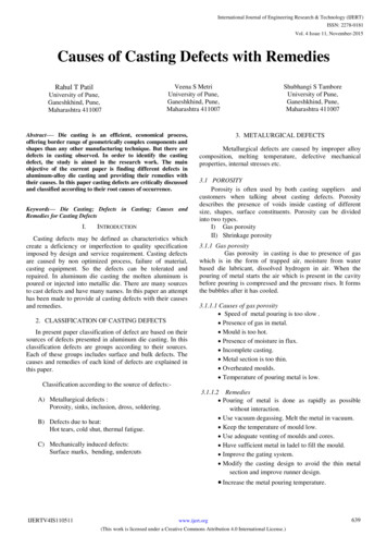
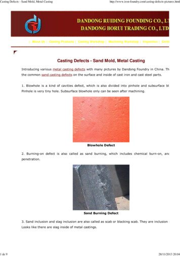
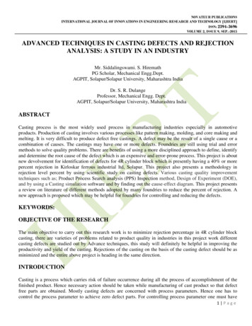
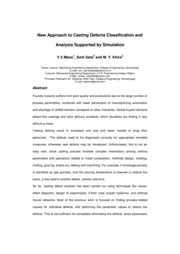
2018 JETIR September 2018, Volume 5, Issue 9Min. mold thickness (in.) 1.18Platen size (in.) 2.95 x 2.95IV.7.940.55 x 40.55www.jetir.org (ISSN-2349-5162)31.5122.0 x 106.3TOOLINGThe infusion shaping procedure utilizes molds,ordinarily made of steel or aluminum, as the customtooling.MOLD BASEThe shape center and form depression are eachmounted to the shape base, which is then settled to theplatens inside the infusion shaping machine. The frontportion of the shape base incorporates a help plate, towhich the form depression is connected, the spruebushing, into which the material will spill out of thespout, and a finding ring, so as to adjust the shape basewith the spout.TWO GATESMOLD CHANNELS:All together for the liquid plastic to stream intothe form depressions, a few channels are incorporatedinto the shape outline. To start with, the liquid plasticenters the shape through the sprue. Extra channels,called sprinters, convey the liquid plastic from the sprueto the greater part of the holes that must be filled.MOLD DESIGNMODELS OF HEAD LAMP WITH DIFFERENTGATE LOCATIONSTHREE GATESIn addition to runners and gates, there are many otherdesign issues that must be considered in the design ofthe molds. Firstly, the mold must allow the moltenplastic to flow easily into all of the cavities.V.MATERIALSThere are many sorts of materials that might beutilized as a part of the infusion shaping procedure.Most polymers might be utilized, including allthermoplastics, some thermosets, and a few elastomers.SINGLE GATEJETIRE006080Journal of Emerging Technologies and Innovative Research (JETIR) www.jetir.org541
2018 JETIR September 2018, Volume 5, Issue 9www.jetir.org (ISSN-2349-5162)The material cost is dictated by the heavinessof material that is required and the unit cost of thatmaterial. The heaviness of material is plainly aconsequence of the part volume and material thickness.Production Cost:The generation cost is fundamentallyascertained from the hourly rate and the processduration. The hourly rate is corresponding to the extentof the infusion shaping machine being utilized, so it isessential to see how the part configuration influencesmachine choice.Tooling Cost:The tooling cost has two fundamental segments- the form base and the machining of the cavities. Thecost of the form base is essentially controlled by thespan of the part's envelope. A bigger part requires abigger, more costly, form base.POSSIBLE DEFECTS :LUBRICATION AND COOLINGClearly, the shape must be cooled all togetherfor the creation to happen. On account of the warmthlimit, minimal effort, and accessibility of water, water isutilized as the essential cooling operator.POWER REQUIREMENTSSpecific gravity(g/cm3)Meltingpoint ( F)Melting point( C)Epoxy1.12 to 1.24248120Phenolic1.34 to 1.95248120Nylon1.01 to 1.15381 to 509194 to 265Polyethylene0.91 to 0.965230 to 243110 to 117Polystyrene1.04 to 1.07338170MaterialINFUSION MOLDING PROCESS CONDITIONS :1. Temperature Control2. Pressure ControlVI.COST DRIVERS3. Molding Cycle4. Holding TimeMaterial Cost:JETIRE0060805. Cooling TimeJournal of Emerging Technologies and Innovative Research (JETIR) www.jetir.org542
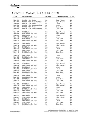
2018 JETIR September 2018, Volume 5, Issue 9VII.RESULTS TABLESINGLE GATECONFIDENCEFILL TIME(Secs)INJECTIONPRESSURE(MPa)WELD LINESAIR TRAPSCYCLE TIME(Secs)QUALITYPREDICTIONSINK MARKSCONFIDENCEFILL TIME(Secs)INJECTIONPRESSURE(MPa)WELD LINESAIR TRAPSCYCLE TIME(Secs)QUALITYPREDICTIONSINK MARKSCASE 1MEDIUM19.58CASE 2MEDIUM4.13CASE 9.05590.00MEDIUMMEDIUMLOW16 % of16 % ofyouryour modelmodel waswas foundfound toto be pronebe proneto sinkto sinkmarks.marks.TWO GATESCASE 2MEDIUMCASE S609.02609.04609.06MEDIUMMEDIUMLOW18 %ofyour modelwas foundto be proneto sinkmarks.18 %ofyourmodelwas foundto beprone tosinkmarks.CASE 1JETIRE006080CASE 2MEDIUMCASE YESYESYESYESYES609.01609.03609.01HIGHMEDIUMLOW17 % of yourmodel wasfound to beprone to sinkmarks.17 % ofyourmodel wasfound tobe proneto sinkmarks.17 % ofyourmodel wasfound tobe proneto sinkmarks.VIII.THREE GATESCONFIDENCEFILL TIME(Secs)INJECTIONPRESSURE(MPa)WELDLINESAIR TRAPSCYCLETIME (Secs)QUALITYPREDICTION16 % ofyour modelwas foundto be proneto sinkmarks.CASE 1MEDIUM18 %of yourmodel wasfound to beprone to sinkmarks.www.jetir.org (ISSN-2349-5162)CONCLUSIONIn this theory, the ideal procedure parametersand the ideal number of entryways required to fill thepart head light with minimum imperfections isinvestigated. The quantity of entryways taken is one,two and three. The procedure parameters considered inthree cases, Case-1: Max Injection Pressure: 180MPa,Mold Temperature: 40 deg C, Melt Temperature: 200deg C, Case-2: Max Injection Pressure: 200MPa, MoldTemperature: 60 deg C, Melt Temperature: 230 deg Cand Case-3: Max Injection Pressure: 230MPa, MoldTemperature: 80 deg C, Melt Temperature: 300 deg C.THE MATERIAL IS ABS PLASTIC.By watching the investigation comes about,utilization of single door is better since 16 % of modelwas observed to be inclined to sink marks when singleentryway is utilized yet when two entryways or threedoors are utilized 18% and 17% of model was observedto be inclined to sink stamps separately. At the pointwhen the procedure parameters are viewed as, takingCase-1 (i.e) Max Injection Pressure: 180MPa, MoldTemperature: 40 deg C, Melt Temperature: 200 deg C isbetter since in three door area, the quality expectation ishigh for case 1 than different cases. So it can be inferredthat to limit sink checks just single entryway andutilizing process parameters Max Injection Pressure:180MPa, Mold Temperature: 40 deg C, MeltTemperature: 200 deg C is better. Be that as it may,considering the quality expectation, fill time and processduration utilizing three entryway areas is better. In anycase, the drawback of utilizing three door areas is thatthere will be more wastage of material.Journal of Emerging Technologies and Innovative Research (JETIR) www.jetir.org543
2018 JETIR September 2018, Volume 5, Issue 9www.jetir.org (ISSN-2349-5162)IX. REFERENCES1.Plastic Injection Molding: Manufacturing ProcessFundamentals by Douglas M. BryceInjection Mold Design: A Design Manual for theThermoplastics Industry by R G W Pye2. The Mold Design Guide by Peter Jones Injection trim- Society of Plastics Engineers Injection trim of plasticsegments by John BownRosato, D. Infusion MoldingHandbook. Second Edition, Chapman and Hall, London,1995.3. Lam, Y.C., Jin, S. Enhancement of the door area forplastic infusion forming. Diary of Injection MoldingTechnology, 20014. Sahputra, I.H. Examination of two streaminvestigation programming for infusion formingapparatus plan. Procedures of the InternationalConference on Industrial Engineering and EngineeringManagement, 2-4 Dec. 2007, Singapore.5. Saman, A.M., Abdullah, A.H., Nor, M.A.M. PCreproduction opportunity in plastic infusion shapeadvancement for car part. Worldwide Conference onComputerTechnology and Development, 13-15 Nov.2009, Kota Kinabalu, MalaysiaJETIRE006080Journal of Emerging Technologies and Innovative Research (JETIR) www.jetir.org544
MINIMIZATION OF SINK MARK DEFECTS IN INJECTION MOLDING PROCESS Naveen Reddy Pothula1, S.Vamshi Krishna2, K.Charantej3, Bodugam Siddartha4 1Assistant Professor in the Department of Mechanical Engineering VITS (N6),